
 My Inquiry
 My Account


Infineon Technologies TLD1311ELXUMA1
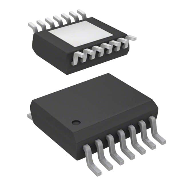
- Part No.:
- TLD1311ELXUMA1
- Manufacturer:
- Infineon Technologies
- Category:
- LED Drivers
- Package:
- 14-LSSOP (0.154", 3.90mm Width) Exposed Pad
- Datasheet:
-
 TLD1311ELXUMA1.pdf
- Description:
- IC LED DRVR LINEAR 120MA 14SSOP
- Quantity:
- Payment:

- Shipping:

Inventory:4,882
Please send an inquiry. Send us your inquiry, and we will respond immediately.
Product details
Overview
TLD1311ELXUMA1 from Infineon is a 3-channel automotive-grade high-side LED current source IC with integrated power stages, designed for precise constant-current driving of red/amber LEDs in exterior lighting (tail/brake, turn indicator) and interior ambient lighting. It delivers up to 120 mA per channel, features ±7% output current accuracy at RSET = 12 kΩ, operates from 5.5 V to 40 V supply, and includes N-1 diagnosis, thermal protection, and reverse polarity protection.
For engineers reviewing the TLD1311ELXUMA1 datasheet, TLD1311ELXUMA1 pinout, TLD1311ELXUMA1 application, or TLD1311ELXUMA1 equivalent, key selection criteria include channel count, high-side current source topology, diagnostic latching behavior, thermal resistance (RthJA ≤ 45 K/W on 2s2p board), and automotive-grade operating range (−40 °C to +150 °C junction temperature).
Technical Context
The TLD1311ELXUMA1 implements three independent high-side current-regulated output stages controlled via external RSET resistor, with current adjustment range spanning 60 mA (nominal, 8–18 V) to 120 mA (max, thermally constrained). Each channel features dedicated open-load and short-to-VS detection routed through the latched N-1 diagnostic pin.
Its internal supply generates stable biasing across the full 5.5–40 V input range; EN and DIS pins provide dual-mode enable/disable control with sleep-mode current as low as 0.1 µA, while ST pin reports real-time status including thermal warning and fault conditions.
Key Specifications
| Parameter | Value and Actual Design Meaning |
|---|---|
| Output Channels | 3 independent high-side current sources, each capable of driving one LED string |
| Max Output Current | 120 mA per channel - supports higher-brightness LEDs under optimized PCB thermal layout |
| Current Accuracy | ±7% at RSET = 12 kΩ - enables predictable luminance without calibration |
| Supply Voltage Range | 5.5 V to 40 V - covers cold-crank (5.5 V) to load-dump (40 V) transients in 12 V automotive systems |
| Sleep Current | 0.1 µA - meets stringent automotive standby power budgets |
| Junction Temp Range | −40 °C to +150 °C - qualified for under-hood and lamp housing environments |
| N-1 Diagnosis | Latched open-load/short-to-VS detection per channel - simplifies ECU-level fault logging |
Pinout & Package
Package: PG-SSOP-14 with exposed thermal pad (EP), lead-free and RoHS-compliant, optimized for automotive thermal cycling reliability.
| Pin/Terminal | Circuit Role | Design Meaning |
|---|---|---|
| VS (Pins 1,2) | Power Supply Input | Battery rail connection (5.5–40 V); requires local 100 nF–1 µF decoupling to GND |
| EN (Pin 3) | Enable Control Input | Active-high logic input; <5 V threshold disables device into 0.1 µA sleep mode |
| DIS (Pin 5) | Disable Input | Hardware override to force all outputs OFF regardless of EN state |
| IN_SET (Pin 6) | Current Set Input | Analog-adjusted reference node; connects to external RSET (e.g., 12 kΩ for 60 mA) |
| N-1 (Pin 7) | Latched Diagnostic Output | Open-drain flag indicating any channel fault (open or short-to-VS), latched until reset |
| GND (Pin 9, EP) | Ground Reference | All ground pins and exposed pad must be connected to common system GND for thermal and EMI performance |
| ST (Pin 10) | Status Output | Real-time status reporting (thermal warning, overcurrent, supply OK) via voltage level |
| OUT1–OUT3 (Pins 11–13) | High-Side Output Terminals | Each drives LED anode; cathodes return to GND; supports PWM dimming via EN or VS modulation |
Key Features
| Feature | Design Value |
|---|---|
| Integrated High-Side Switches | Three matched MOSFET-based current sources eliminate need for external sense resistors or discrete drivers |
| Thermal Protection | Automatic shutdown at Tj ≥ 150 °C with hysteresis; resumes operation after cooldown |
| Reverse Polarity Protection | Withstands −16 V applied to VS - protects against battery misconnection during service |
| Undervoltage Lockout (UVLO) | Enables only above VS(POR) = 5 V - prevents erratic startup during cranking |
| EMI-Optimized Layout Support | Exposed thermal pad and dedicated VS/GND pin pairing reduce loop inductance and radiated emissions |
Applications
| Rear Combination Lamp | Dashboard Ambient Lighting |
|---|---|
Use Scenario: Tail light assembly integrating brake, position, and turn functions in single housing. IC Role / Device Role / Timing Role: High-side current source controlling three independent LED strings (red brake, amber turn, white position) with synchronized dimming and fault reporting. Use Value: Enables compact, thermally robust design meeting ECE R7 and SAE J585 photometric requirements while reducing BOM count by 3× vs. discrete solutions. | Use Scenario: RGB-mixed ambient lighting behind instrument cluster trim with dynamic color tuning. IC Role / Device Role / Timing Role: Constant-current driver for three monochrome LED channels (e.g., red, green, blue), each independently PWM-dimmable via EN pin. Use Value: Delivers flicker-free, color-stable illumination with ±7% current matching across channels - critical for uniform hue perception. |
| Side Marker Light | Interior Dome Light |
Use Scenario: Low-profile side marker module mounted in door pillar or fender with minimal heat sinking. IC Role / Device Role / Timing Role: Single-channel high-side driver (using OUT1 only) with N-1 latch for open-circuit detection during vehicle diagnostics. Use Value: Supports ASAM MCD-2 MC diagnostic protocols via latched N-1 signal - eliminates need for external monitoring circuitry. | Use Scenario: Overhead dome light with soft-on/off fade and occupancy-sensing dimming profiles. IC Role / Device Role / Timing Role: Three-channel driver powering white LEDs in parallel strings, with EN-controlled ramp-up/down timing coordinated by MCU. Use Value: Achieves <100 ms smooth transition between states using internal current slew rate control - avoids perceptible flicker during transitions. |
Equivalent & Alternatives
The following parts are listed as comparable options for similar high-side LED driver applications.
| Alternative Part | Technical Difference | Application Difference | Selection Advice |
|---|---|---|---|
| ASL3416SHN | 4-channel, 150 mA max per channel; integrated SPI interface; no N-1 latch | Requires MCU firmware integration for diagnostics; better suited for adaptive lighting with dynamic channel reconfiguration | Select when SPI-based configuration and higher per-channel current are required, and diagnostic latching is handled externally |
| TLD2314EL | 4-channel, same PG-SSOP-14 package; identical N-1 latch and thermal protection; 100 mA max per channel | Lower max current limits thermal headroom in high-ambient environments but improves margin for long-life reliability | Select when lower thermal stress and proven field reliability in 125 °C ambient applications are prioritized over peak brightness |
Compared with ASL3416SHN and TLD2314EL, the TLD1311ELXUMA1 offers optimal balance of diagnostic fidelity (latched N-1), thermal robustness (150 °C Tj), and minimal system overhead - making it ideal for cost-sensitive, safety-critical exterior lighting where deterministic fault reporting is mandatory.
Availability
TLD1311ELXUMA1 is available at Aetrix Electronics and suitable for rear combination lamps, dashboard ambient lighting, side marker lights, and interior dome lighting requiring stable component supply across automotive production lifecycles.
Supply support for TLD1311ELXUMA1 includes scheduled delivery planning, volume procurement assistance, BOM continuity management, traceable sourcing, and lifecycle availability coordination for OEM customers, industrial embedded developers, connected-device designers, and electronics production programs.
Manufacturer
Infineon Technologies AG is a German semiconductor manufacturer specializing in power management, automotive ICs, and security solutions, with global manufacturing and automotive qualification expertise.
The LITIX™Basic product line delivers robust, AEC-Q100-qualified LED drivers for cost-sensitive automotive lighting, emphasizing functional safety, thermal resilience, and diagnostic completeness without MCU dependency.
FAQ
What is the recommended RSET value for 60 mA output per channel?
The datasheet specifies RSET = 12 kΩ for nominal 60 mA output per channel under 8–18 V supply conditions. This value yields ±7% current accuracy and is validated for thermal stability on standard 2s2p FR4 boards. Lower values increase current linearly but require verification of junction temperature rise and RthJA derating.
How does the N-1 latch function during multiple channel faults?
The N-1 pin latches on the first detected fault (open-load or short-to-VS) across any of the three channels and remains asserted until the device is power-cycled or reset via EN pin toggle. It does not distinguish which channel failed, serving as a system-level fault flag for ECU diagnostics rather than per-channel reporting.
Can the TLD1311ELXUMA1 drive white LEDs with forward voltage > 3.2 V per diode?
Yes - each channel supports up to 40 V output voltage (VOUTx), enabling series strings of up to 10 white LEDs (assuming VF ≈ 3.5 V at 60 mA). The high-side architecture maintains regulation as long as VS exceeds total LED string VF plus dropout (typically < 1.2 V), verified across the full 5.5–40 V supply range.
Is the exposed thermal pad electrically isolated from internal circuitry?
No - the exposed pad (EP) is internally connected to GND and must be soldered to a PCB GND plane. It serves both thermal conduction (RthJC = 8 K/W) and EMI suppression. Floating or voltage-biased connection violates absolute maximum ratings and risks thermal runaway or ESD damage.
TLD1311ELXUMA1 Specifications
- Product attributes
- Attribute value
- Manufacturer:
- Infineon Technologies
- Series:
- LITIX™
- Package/Case:
- 14-LSSOP (0.154", 3.90mm Width) Exposed Pad
- Packaging:
- Tape & Reel (TR)
- Product Status:
- Obsolete
- Type:
- Linear
- Topology:
- -
- Internal Switch(s):
- Yes
- Number of Outputs:
- 3
- Voltage - Supply (Min):
- 5.5V
- Voltage - Supply (Max):
- 40V
- Voltage - Output:
- 40V
- Current - Output / Channel:
- 120mA
- Frequency:
- -
- Dimming:
- -
- Applications:
- -
- Operating Temperature:
- -40°C ~ 150°C (TJ)
- Grade:
- Automotive
- Qualification:
- -
- Mounting Type:
- Surface Mount
- Supplier Device Package:
- PG-SSOP-14-5
TLD1311ELXUMA1 FAQ
1.How can I place an order for TLD1311ELXUMA1 through Aetrix?
Please submit a Request for Quotation (RFQ) for TLD1311ELXUMA1 on Aetrix. Our sales agent will provide a competitive quotation and guide you through the order confirmation once you accept the terms.
2.Are the price and stock information for TLD1311ELXUMA1 reliable?
The price and inventory of TLD1311ELXUMA1 are updated periodically and may fluctuate due to market conditions. Stock and pricing data are typically refreshed every 24 hours. Quotation validity for TLD1311ELXUMA1 is usually 5 days.
3.What payment methods are accepted for TLD1311ELXUMA1?
We accept Wire Transfer, PayPal, Credit Card, Western Union, MoneyGram, and Escrow for TLD1311ELXUMA1 transactions.
Note: Certain payment methods may incur a processing fee.
4.How is shipping managed for TLD1311ELXUMA1?
TLD1311ELXUMA1 orders can be shipped via leading logistics carriers, including DHL, UPS, FedEx, TNT, or Registered Mail.
Once your TLD1311ELXUMA1 order is processed, you will receive an email with the shipment details and tracking number.
Note: Tracking information may take up to 24 hours to appear. Express delivery typically takes 3–5 business days.
5.How can I obtain technical support or documentation for TLD1311ELXUMA1?
For technical support, including TLD1311ELXUMA1 datasheets, pinout diagrams, or application guidance, please contact our engineering support team. They can provide detailed documentation and assistance for your TLD1311ELXUMA1 requirements.
6.How does Aetrix verify that TLD1311ELXUMA1 is sourced from the original manufacturer or authorized distributors?
All TLD1311ELXUMA1 products on Aetrix are procured from qualified distributors and authorized channels. Our dedicated quality assurance team conducts strict verification, including traceability checks and, if necessary, third-party testing. This ensures that TLD1311ELXUMA1 meets industry standards.
7.What is the process for return or replacement of TLD1311ELXUMA1?
All TLD1311ELXUMA1 units undergo pre-shipment inspection (PSI). If there is an issue with TLD1311ELXUMA1, returns or replacements are accepted under the following conditions:
1.Quantity discrepancies, incorrect items, or visible external defects (such as breakage or corrosion), acknowledged by Aetrix.
2.The issue is reported within 90 days of delivery.
3.The TLD1311ELXUMA1 part is unused and in its original packaging.
Return procedure for TLD1311ELXUMA1:
1.Submit a request within 90 days.
2.Obtain a Return Material Authorization (RMA) from Aetrix.
TLD1311ELXUMA1 Tags

-
BCR402RE6327HTSA1
Infineon Technologies

-
BCR430UXTSA2
Infineon Technologies

-
BCR420UE6433HTMA1
Infineon Technologies
-
BCR420UE6327HTSA1
Infineon Technologies
-
BCR421UE6327HTSA1
Infineon Technologies

-
LYT1604D-TL
Power Integrations

-
HV9910CLG-G
Microchip Technology

-
CL2N8-G
Microchip Technology

-
BCR420UW6-7
Diodes Incorporated
-
BCR421UW6-7
Diodes Incorporated

-
BCR420UFD-7
Diodes Incorporated
-
BCR421UFD-7
Diodes Incorporated
Tech Hub

An engineering guide to LED driver operation, constant-current and constant-voltage outputs, linear and switching topologies, dimming, IC selection, calculations, replacement compatibility, and fault c…

Operational amplifier guide covering op amp basics, feedback, ideal vs real op amps, common configurations, buffer circuits, offset, bias current, gain-bandwidth, slew rate, rail-to-rail limits and sel…

Jumper cables guide covering safe connection order, red and black clamp placement, final ground connection, cable gauge, length, clamp quality, copper vs CCA cables, jump starter comparison and battery…

LDO regulator guide covering low dropout voltage, power dissipation, thermal design, PSRR, output noise, capacitor stability, adjustable LDO circuits, LDO vs buck converter and datasheet selection chec…

Conditional Access Module guide covering CAM meaning, CI/CI+ interface, smart card authorization, DVB security workflow, TV and set-top box compatibility, internal electronics, ESD protection, connecto…

Guide to electronic component obsolescence covering EOL risk, PCN/PDN notices, last-time buy planning, replacement options, form-fit-function validation, counterfeit risk and BOM lifecycle management.

18650 battery guide covering lithium-ion cell basics, 3.6V/3.7V voltage, 4.2V charging, mAh and Wh capacity, protected cells, chargers, BMS, series-parallel packs, holders, welding and sourcing checks.…

Hall effect sensor guide covering working principle, linear and digital sensors, Arduino circuits, current sensing, speed detection, automotive applications, A3144 examples, signal filtering and datash…

Product Change Notification guide for electronic components, covering PCN meaning, PCN vs PDN/EOL, common change types, risk levels, form-fit-function review, engineering validation, BOM control, LTB/L…

A practical guide to blend door actuators, covering HVAC function, symptoms, location, AC and heater issues, reset and calibration, replacement cost, electrical diagnosis, compatibility checks, and rep…


