
 My Inquiry
 My Account


Infineon Technologies TLD23313EPXUMA1
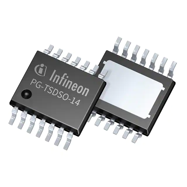
- Part No.:
- TLD23313EPXUMA1
- Manufacturer:
- Infineon Technologies
- Category:
- LED Drivers
- Package:
- 14-TSSOP (0.154", 3.90mm Width) Exposed Pad
- Datasheet:
-
 TLD23313EPXUMA1.pdf
- Description:
- IC LED DRVR LIN PWM 60MA 14TSDSO
- Quantity:
- Payment:

- Shipping:

Inventory:3,475
Please send an inquiry. Send us your inquiry, and we will respond immediately.
Product details
Overview
TLD23313EPXUMA1 from Infineon is a triple-channel automotive-grade high-side LED driver IC with integrated protected current sources, designed to drive up to 80 mA per channel across red/amber LEDs in stop/tail and turn indicator functions. It features ±5% current accuracy at 300 mA setpoint, 0.1 µA sleep-mode current, and reverse-polarity protection for low-battery operation down to 5.5 V supply.
For engineers reviewing the TLD23313EPXUMA1 datasheet, TLD23313EPXUMA1 pinout, TLD23313EPXUMA1 application, or TLD23313EPXUMA1 equivalent, this device supports precise digital dimming, intelligent shared error-network fault management (up to 16 devices), and single-LED short detection-critical for AEC-Q100-compliant exterior lighting systems requiring thermal robustness and load diagnosis.
Technical Context
The TLD23313EPXUMA1 implements three independent high-side current-regulated output stages controlled via dedicated IN_SETx pins, each adjustable by external resistors or reference sources. Its internal supply regulation enables stable operation across 5.5–40 V input, while thermal and reverse-battery protections operate autonomously without host intervention.
Fault diagnostics include open-load, short-to-GND, and single-LED short detection using SLS_REF and DS pins, with configurable retry strategies via capacitor timing on D and DS. The ERRN pin provides open-drain error signaling compatible with daisy-chained multi-device networks using a single external pull-up resistor.
Key Specifications
| Parameter | Value and Actual Design Meaning |
|---|---|
| Operating Voltage | 5.5 V to 40 V - supports full automotive battery range including cold-crank (5.5 V) and load-dump (40 V) |
| Max Output Current | 80 mA per channel - sufficient to drive 3× red LEDs per channel at 60 mA nominal under 8–18 V supply |
| Current Accuracy | ±5% at 300 mA setpoint - ensures consistent luminance across channels without calibration |
| Sleep Current | 0.1 µA - enables always-on vehicle functions with negligible battery drain |
| Fault Current Draw | ≤850 µA when ERRN-disabled - minimizes system power impact during cascaded fault reporting |
| Junction Temp Range | −40°C to +150°C - qualified for under-hood placement per AEC-Q100 Grade 0 |
| Package Thermal RθJA | Not specified in datasheet - requires PCB copper area design per PG-TSDSO-14 exposed pad (EP) grounding |
Pinout & Package
Delivered in PG-TSDSO-14 package with exposed thermal pad (EP) connected to GND, enabling efficient heat dissipation in compact automotive lighting modules.
| Pin/Terminal | Circuit Role | Design Meaning |
|---|---|---|
| 1 (SLS_REF) | Single LED Short reference input | Adjusts internal SLS threshold voltage via external resistor; connect to GND if unused |
| 2 (IN_SET1) | Channel 1 current control input | Sets OUT1 current (0–80 mA) via resistor or reference source; supports daisy-chained LITIX™ Companion |
| 3 (IN_SET2) | Channel 2 current control input | Sets OUT2 current independently; identical electrical behavior to IN_SET1 |
| 4 (IN_SET3) | Channel 3 current control input | Sets OUT3 current independently; enables RGB or multi-function lighting with per-channel tuning |
| 5 (DS) | Single LED short delay/restart | Configures SLS retry timing via capacitor; open or GND-connected for low-power mode |
| 6 (PWMI) | PWM dimming input | Accepts external PWM signal for analog-equivalent brightness control; tie to GND if unused |
| 7 (D) | Disable/delay error input | Controls fault response timing and diagnostic enable/disable via capacitor or GND connection |
| 8 (GND) | Signal ground | Reference for all analog and digital inputs; must be low-impedance path to EP |
| 9 (EN/DEN) | Enable/diagnosis control | Activates outputs and load diagnosis when pulled above threshold; uses resistor divider or Zener |
| 10 (VS) | Main supply input | Connects to battery or switched 12 V rail; includes internal ESD and overload protection |
| 11 (OUT3) | Channel 3 high-side output | Drives LED anode; withstands 40 V reverse voltage during polarity reversal events |
| 12 (OUT2) | Channel 2 high-side output | Identical to OUT3; supports independent load switching and diagnosis |
| 13 (OUT1) | Channel 1 high-side output | Identical to OUT2/OUT3; enables three-zone lighting control (e.g., tail + brake + turn) |
| 14 (ERRN) | Error flag I/O | Open-drain active-low output; shares common pull-up for multi-device error bus |
| EP (Exposed Pad) | Thermal & ground connection | Mandatory GND connection for thermal performance and EMI reduction; soldered to PCB copper |
Key Features
| Feature | Design Value |
|---|---|
| Triple high-side current sources | Three independent 80 mA channels with matched accuracy (±5%) and thermal derating awareness |
| Intelligent multi-device error network | Up to 16 TLD23313EPXUMA1 devices share one ERRN bus with single external pull-up resistor |
| Reverse polarity protection | Operates down to 5.5 V supply with no external diode required, reducing BOM count and voltage drop |
| Single LED short (SLS) detection | Detects short between two adjacent LEDs in series string using SLS_REF/DS configuration |
| Low-power fault management | Draws ≤850 µA during fault reporting and maintains <0.1 µA sleep current for always-on systems |
Applications
| Automotive Stop/Tail Lighting | Turn Signal Indicators |
|---|---|
Use Scenario: Dual-function rear lamp housing where same physical LED array serves both stop (high-intensity) and tail (low-intensity) roles. IC Role / Device Role / Timing Role: High-side driver providing independent current control per function via IN_SETx and PWMI modulation. Use Value: Eliminates need for separate current-setting resistors or external FETs, reducing PCB area and thermal stress on LEDs. | Use Scenario: Sequential turn indicators using three discrete LED zones activated in timed sequence. IC Role / Device Role / Timing Role: Triple-channel driver enabling synchronized or staggered activation of OUT1–OUT3 with programmable current per zone. Use Value: Supports animated wiping effects without MCU GPIO expansion, leveraging built-in fault-aware timing control. |
| Daytime Running Lights (DRL) | Interior Ambient Lighting |
Use Scenario: Linear LED bar mounted behind translucent lens, requiring uniform brightness and thermal stability over 10+ years. IC Role / Device Role / Timing Role: Constant-current source maintaining 60 mA per channel across temperature and input voltage variation (8–18 V). Use Value: Delivers consistent lumen output without feedback loop or microcontroller, meeting ECE R87 photometric requirements. | Use Scenario: RGB ambient lighting strip behind dashboard trim, requiring smooth color blending and low-noise dimming. IC Role / Device Role / Timing Role: Three-channel driver controlling red, green, and blue LED strings independently via IN_SETx and PWMI. Use Value: Enables 256-level dimming per channel with <±5% current matching, critical for accurate white-point tuning. |
Equivalent & Alternatives
The following parts are listed as comparable options for similar triple-channel high-side LED driver applications.
| Alternative Part | Technical Difference | Application Difference | Selection Advice |
|---|---|---|---|
| ASL3416SHUML | Quad-channel, higher max current (120 mA), integrated SPI interface, no SLS detection | Requires MCU for configuration; better suited for dynamic adaptive lighting than fixed-function tail lamps | Select when SPI-based reconfiguration or >80 mA per channel is required; not drop-in for TLD23313EPXUMA1 PCB |
| TLD20313EPXUMA1 | Same pinout and footprint, but only two channels and no SLS_REF/DS pins | Lacks single-LED short detection and third channel; lower BOM cost for dual-function designs | Select for cost-sensitive dual-channel applications where SLS is not mandated by OEM specification |
Compared with ASL3416SHUML and TLD20313EPXUMA1, the TLD23313EPXUMA1 uniquely balances triple-channel capability, AEC-Q100 qualification, SLS diagnostics, and minimal external components-making it optimal for cost-constrained yet safety-critical exterior lighting nodes without MCU overhead.
Availability
TLD23313EPXUMA1 is available at Aetrix Electronics and suitable for automotive exterior lighting, interior ambient lighting, and industrial status indication requiring stable component supply, AEC-Q100 compliance, and thermal resilience up to +150°C junction temperature.
Supply support for TLD23313EPXUMA1 includes scheduled delivery planning, volume procurement assistance, BOM continuity management, traceable sourcing, and lifecycle availability coordination for OEM customers, industrial embedded developers, connected-device designers, and electronics production programs.
Manufacturer
Infineon Technologies is a German semiconductor manufacturer specializing in power management, automotive ICs, and sensor solutions, with global manufacturing and automotive qualification infrastructure.
The LITIX™ Basic+ product line delivers robust, cost-optimized LED drivers for automotive lighting functions-including stop, tail, turn, DRL, and interior illumination-designed to reduce system complexity while meeting stringent AEC-Q100 reliability standards.
FAQ
What is the maximum allowable thermal resistance (RthJA) to sustain 80 mA per channel continuously?
The datasheet does not specify a maximum RthJA value but states that 80 mA operation depends on actual board-level thermal resistance. At 60 mA nominal (8–18 V), continuous operation is guaranteed within −40°C to +150°C junction range. For 80 mA, designers must ensure PCB copper area and EP soldering meet Infineon's layout guidelines in Section 8 to avoid exceeding TJ(max) = 150°C under worst-case ambient and power dissipation.
Can the ERRN pin be directly connected to a microcontroller GPIO without a pull-up resistor?
No. ERRN is an open-drain output and requires an external pull-up resistor (typically 4.7 kΩ to VS) to generate a valid logic-high level. Connecting ERRN directly to a GPIO without pull-up results in undefined or floating state during normal operation. The resistor value must also support bus capacitance when daisy-chaining multiple devices per the error network topology described in Section 6.1.
Is reverse polarity protection active during sleep mode?
Yes. Reverse polarity protection remains fully functional in sleep mode, allowing the device to survive battery misconnection events even when EN/DEN is deasserted and outputs are disabled. This is confirmed by the absolute maximum rating table (Table 2), which specifies −18 V minimum VS and −18 V minimum VEN/DEN–VS, and by the functional range definition covering operation down to 5.5 V supply with reverse protection enabled.
How does the SLS (Single LED Short) detection differ from standard short-to-GND detection?
SLS detects a short between two adjacent LEDs in a series string (e.g., anode of LED2 shorted to cathode of LED1), whereas standard short-to-GND detects OUTx directly shorted to GND. SLS uses the SLS_REF pin to set a reference voltage and the DS pin to configure timing, enabling discrimination between true load shorts and partial-string faults-critical for diagnosing degraded LED arrays without false positives in multi-LED chains.
TLD23313EPXUMA1 Specifications
- Product attributes
- Attribute value
- Manufacturer:
- Infineon Technologies
- Series:
- LITIX™
- Package/Case:
- 14-TSSOP (0.154", 3.90mm Width) Exposed Pad
- Packaging:
- Tape & Reel (TR)
- Product Status:
- Active
- Type:
- Linear
- Topology:
- -
- Internal Switch(s):
- Yes
- Number of Outputs:
- 3
- Voltage - Supply (Min):
- 5.5V
- Voltage - Supply (Max):
- 40V
- Voltage - Output:
- 40V
- Current - Output / Channel:
- 60mA
- Frequency:
- -
- Dimming:
- PWM
- Applications:
- -
- Operating Temperature:
- -40°C ~ 150°C (TJ)
- Grade:
- Automotive
- Qualification:
- AEC-Q100
- Mounting Type:
- Surface Mount
- Supplier Device Package:
- PG-TSDSO-14
TLD23313EPXUMA1 FAQ
1.How can I place an order for TLD23313EPXUMA1 through Aetrix?
Please submit a Request for Quotation (RFQ) for TLD23313EPXUMA1 on Aetrix. Our sales agent will provide a competitive quotation and guide you through the order confirmation once you accept the terms.
2.Are the price and stock information for TLD23313EPXUMA1 reliable?
The price and inventory of TLD23313EPXUMA1 are updated periodically and may fluctuate due to market conditions. Stock and pricing data are typically refreshed every 24 hours. Quotation validity for TLD23313EPXUMA1 is usually 5 days.
3.What payment methods are accepted for TLD23313EPXUMA1?
We accept Wire Transfer, PayPal, Credit Card, Western Union, MoneyGram, and Escrow for TLD23313EPXUMA1 transactions.
Note: Certain payment methods may incur a processing fee.
4.How is shipping managed for TLD23313EPXUMA1?
TLD23313EPXUMA1 orders can be shipped via leading logistics carriers, including DHL, UPS, FedEx, TNT, or Registered Mail.
Once your TLD23313EPXUMA1 order is processed, you will receive an email with the shipment details and tracking number.
Note: Tracking information may take up to 24 hours to appear. Express delivery typically takes 3–5 business days.
5.How can I obtain technical support or documentation for TLD23313EPXUMA1?
For technical support, including TLD23313EPXUMA1 datasheets, pinout diagrams, or application guidance, please contact our engineering support team. They can provide detailed documentation and assistance for your TLD23313EPXUMA1 requirements.
6.How does Aetrix verify that TLD23313EPXUMA1 is sourced from the original manufacturer or authorized distributors?
All TLD23313EPXUMA1 products on Aetrix are procured from qualified distributors and authorized channels. Our dedicated quality assurance team conducts strict verification, including traceability checks and, if necessary, third-party testing. This ensures that TLD23313EPXUMA1 meets industry standards.
7.What is the process for return or replacement of TLD23313EPXUMA1?
All TLD23313EPXUMA1 units undergo pre-shipment inspection (PSI). If there is an issue with TLD23313EPXUMA1, returns or replacements are accepted under the following conditions:
1.Quantity discrepancies, incorrect items, or visible external defects (such as breakage or corrosion), acknowledged by Aetrix.
2.The issue is reported within 90 days of delivery.
3.The TLD23313EPXUMA1 part is unused and in its original packaging.
Return procedure for TLD23313EPXUMA1:
1.Submit a request within 90 days.
2.Obtain a Return Material Authorization (RMA) from Aetrix.
TLD23313EPXUMA1 Tags

-
BCR402RE6327HTSA1
Infineon Technologies

-
BCR430UXTSA2
Infineon Technologies

-
BCR420UE6433HTMA1
Infineon Technologies
-
BCR420UE6327HTSA1
Infineon Technologies
-
BCR421UE6327HTSA1
Infineon Technologies

-
LYT1604D-TL
Power Integrations

-
HV9910CLG-G
Microchip Technology

-
CL2N8-G
Microchip Technology

-
BCR420UW6-7
Diodes Incorporated
-
BCR421UW6-7
Diodes Incorporated

-
BCR420UFD-7
Diodes Incorporated
-
BCR421UFD-7
Diodes Incorporated
Tech Hub

Operational amplifier guide covering op amp basics, feedback, ideal vs real op amps, common configurations, buffer circuits, offset, bias current, gain-bandwidth, slew rate, rail-to-rail limits and sel…

Jumper cables guide covering safe connection order, red and black clamp placement, final ground connection, cable gauge, length, clamp quality, copper vs CCA cables, jump starter comparison and battery…

LDO regulator guide covering low dropout voltage, power dissipation, thermal design, PSRR, output noise, capacitor stability, adjustable LDO circuits, LDO vs buck converter and datasheet selection chec…

Conditional Access Module guide covering CAM meaning, CI/CI+ interface, smart card authorization, DVB security workflow, TV and set-top box compatibility, internal electronics, ESD protection, connecto…

Guide to electronic component obsolescence covering EOL risk, PCN/PDN notices, last-time buy planning, replacement options, form-fit-function validation, counterfeit risk and BOM lifecycle management.

18650 battery guide covering lithium-ion cell basics, 3.6V/3.7V voltage, 4.2V charging, mAh and Wh capacity, protected cells, chargers, BMS, series-parallel packs, holders, welding and sourcing checks.…

Hall effect sensor guide covering working principle, linear and digital sensors, Arduino circuits, current sensing, speed detection, automotive applications, A3144 examples, signal filtering and datash…

Product Change Notification guide for electronic components, covering PCN meaning, PCN vs PDN/EOL, common change types, risk levels, form-fit-function review, engineering validation, BOM control, LTB/L…

A practical guide to blend door actuators, covering HVAC function, symptoms, location, AC and heater issues, reset and calibration, replacement cost, electrical diagnosis, compatibility checks, and rep…

Engineering guide to Raspberry Pi alternatives, covering chip-level differences, Orange Pi, ROCK, Jetson, Banana Pi, NanoPi, Compute Module, Pico, GPIO, camera, HAT compatibility, and replacement risks…


