
 My Inquiry
 My Account


Infineon Technologies TLD55012QVXUMA1
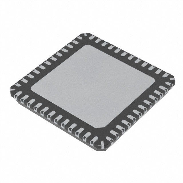
- Part No.:
- TLD55012QVXUMA1
- Manufacturer:
- Infineon Technologies
- Category:
- LED Drivers
- Package:
- 48-VFQFN Exposed Pad
- Datasheet:
-
 TLD55012QVXUMA1.pdf
- Description:
- IC LED DRIVER CTRLR PWM 48VQFN
- Quantity:
- Payment:

- Shipping:

Inventory:2,035
Please send an inquiry. Send us your inquiry, and we will respond immediately.
Product details
Overview
TLD55012QVXUMA1 from Infineon is a dual-channel synchronous DC/DC buck controller for high-power automotive LED drivers, supporting 4.5 V–55 V power-stage input, 200–700 kHz adjustable switching frequency, and SPI-based diagnostics/control. It delivers ±3% LED current accuracy, constant-current/constant-voltage regulation, and AEC-Q100 Grade 1 qualification (−40°C to +125°C) in a PG-VQFN-48 package.
For engineers reviewing the TLD55012QVXUMA1 datasheet, TLD55012QVXUMA1 pinout, TLD55012QVXUMA1 application, or TLD55012QVXUMA1 equivalent, key selection criteria include dual-channel gate driver capability (HSGD1/LSGD1 & HSGD2/LSGD2), programmable spread spectrum for EMC compliance, limp-home fail-safe activation via LHI, and independent analog/PWM dimming per channel.
Technical Context
The device implements two independent current-mode synchronous buck controllers with dedicated feedback loops (FBH1/FBL1, FBH2/FBL2), each featuring slope compensation, soft-start (SOFT_START1/SOFT_START2), and output current monitoring (IOUTMON1/IOUTMON2). Gate drivers support external NMOS with RDS(ON)_PU = 2.3 Ω and RDS(ON)_PD = 1.2 Ω at 25°C.
Its SPI interface (CSN/SI/SCLK/SO, up to 5 MHz) enables real-time register access for diagnostics-including open-load detection, overtemperature prewarning, and latched fault reporting-while FREQ and SYNC pins allow resistor-programmed or externally synchronized switching frequency control.
Key Specifications
| Parameter | Value and Actual Design Meaning |
|---|---|
| VIN Range | 4.5 V to 40 V - powers internal bias circuitry; separate from higher 55 V power-stage input (VPOW) |
| VPOW Range | 4.5 V to 55 V - direct connection to high-side MOSFET source; supports wide automotive battery transients |
| fSW Range | 200 kHz to 700 kHz - adjustable via external resistor (FREQ pin) or external clock (SYNC pin) |
| LED Current Accuracy | ±3% - achieved via calibrated current-sense amplifier and dedicated SET1/SET2 analog trim inputs |
| Efficiency | Up to 96% - enabled by synchronous rectification, low RDS(ON) gate drivers, and forced CCM mode |
| Operating Temp | −40°C to +125°C - AEC-Q100 Grade 1 qualified; thermal shutdown with autorestart ensures robustness |
| SPI Clock Max | 5 MHz - supports fast configuration and diagnostic readback without CPU overhead |
Pinout & Package
Package: PG-VQFN-48 (7 mm × 7 mm, 0.5 mm pitch, exposed thermal pad). Thermally enhanced layout requires direct connection of EP to inner GND plane via thermal vias.
| Pin/Terminal | Circuit Role | Design Meaning |
|---|---|---|
| HSGD1, HSGD2 | High-Side Gate Driver Output | Drives top NMOS gates with bootstrap-referenced voltage; requires BST1/SWN1 and BST2/SWN2 capacitor networks |
| LSGD1, LSGD2 | Low-Side Gate Driver Output | Drives bottom NMOS gates referenced to PGND1/PGND2; supports continuous conduction mode (CCM) |
| SWCS1, SWCS2 | Current Sense Input (+) | Differential input for inductor current sensing; paired with SGND1/SGND2 for accurate peak-current mode control |
| IOUTMON1, IOUTMON2 | Output Current Monitor | Analog voltage output proportional to LED current (linear scaling); used for closed-loop calibration or safety monitoring |
| LHI | Limp-Home Activation Input | Pull-low to force fail-safe operation: reduces LED current to predefined safe level without full shutdown |
| FREQ | Frequency Select Input | Resistor-to-GND sets fSW within 200–700 kHz range; enables EMI optimization without changing layout |
Key Features
| Feature | Design Value |
|---|---|
| Dual independent buck channels | Separate COMP1/COMP2, SOFT_START1/SOFT_START2, and FBH/FBL pairs enable asymmetric load design and independent loop tuning |
| Auto spread spectrum modulation | Reduces peak EMI by dithering switching frequency; no external components required |
| Programmable limp-home mode | LHI pin triggers hardware-level current reduction to maintain partial lighting during fault-critical for ASIL-B compliant headlamps |
| Integrated current sense amplifiers | SWCS1/SGND1 and SWCS2/SGND2 differential inputs eliminate need for external sense resistors on high-side path |
| Robust protection suite | Includes input UVLO (EN/INUVLO), overtemperature shutdown with prewarning, open-load detection, and short-to-ground detection per channel |
Applications
| Automotive Low Beam Headlamp | Automotive High Beam Headlamp |
|---|---|
|
Use Scenario: Primary illumination module in adaptive driving beam (ADB) systems requiring precise current control across multiple LED strings. IC Role / Device Role / Timing Role: Dual-channel synchronous buck controller regulating two independent LED arrays with coordinated PWM dimming and fault reporting. Use Value: Enables dynamic beam shaping via per-string current adjustment while maintaining ±3% matching and <10 µs fault response time. |
Use Scenario: High-intensity forward lighting in premium vehicle platforms where thermal management and EMI compliance are critical. IC Role / Device Role / Timing Role: Dual-channel DC/DC controller delivering up to 50 V output per channel with spread-spectrum switching to meet CISPR-25 Class 5 limits. Use Value: Achieves >95% efficiency at 3 A per channel while reducing conducted emissions by 8 dBµV through auto-dithered fSW. |
| Matrix LED Pixel Module | Automotive Daytime Running Light (DRL) |
|
Use Scenario: Individual pixel control in next-generation matrix headlamps with >100 addressable LEDs per array. IC Role / Device Role / Timing Role: Dual-channel current regulator with SPI-configurable dimming curves and real-time current monitoring per string. Use Value: Supports frame-synchronized dimming updates via SPI write bursts, enabling sub-millisecond pixel reconfiguration without MCU intervention. |
Use Scenario: Safety-critical DRL system requiring continuous operation under battery voltage fluctuations (6–16 V). IC Role / Device Role / Timing Role: Dual-channel buck controller with VIN range down to 4.5 V and built-in input undervoltage lockout (EN/INUVLO pin). Use Value: Maintains stable 120 mA per channel output even during cold-crank events (6.5 V min), ensuring regulatory-compliant luminance. |
Equivalent & Alternatives
The following parts are listed as comparable options for similar dual-channel LED controller applications.
| Alternative Part | Technical Difference | Application Difference | Selection Advice |
|---|---|---|---|
| MAX20052ATP/V+T | Single-channel controller; requires dual ICs for two outputs; no integrated spread spectrum; lower max VOUT (40 V) | Targeted at cost-sensitive non-automotive LED lighting; lacks AEC-Q100 qualification and limp-home function | Select when dual independent channels are not required and thermal derating above 105°C is unnecessary |
| TPS92692QPWPRQ1 | Single-channel, current-sink topology; supports up to 65 V but no synchronous buck architecture; no SPI diagnostics | Designed for rear lighting (brake/tail lamps); lacks PWM dimming synchronization and channel-to-channel current matching | Prefer for high-side current sink applications where LED cathode grounding simplifies thermal layout |
Compared with MAX20052ATP/V+T and TPS92692QPWPRQ1, TLD55012QVXUMA1 uniquely integrates dual synchronous buck control, AEC-Q100 Grade 1 operation, hardware limp-home, and SPI-configurable spread spectrum-making it the only solution qualified for front-end matrix headlamp architectures requiring functional safety and EMI robustness.
Availability
TLD55012QVXUMA1 is available at Aetrix Electronics and suitable for automotive exterior lighting, adaptive driving beam systems, and matrix LED headlamp modules requiring stable component supply, long-term lifecycle support, and AEC-Q100 compliance.
Supply support for TLD55012QVXUMA1 includes scheduled delivery planning, volume procurement assistance, BOM continuity management, traceable sourcing, and lifecycle availability coordination for OEM customers, industrial embedded developers, connected-device designers, and electronics production programs.
Manufacturer
Infineon Technologies is a German semiconductor manufacturer specializing in power management, automotive electronics, and industrial control ICs, with global manufacturing and qualification infrastructure.
TLD55012QVXUMA1 belongs to the LITIX™ Power Flex family-designed specifically for scalable, high-efficiency LED driver solutions in ASIL-B automotive lighting systems requiring functional safety, diagnostics, and thermal resilience.
FAQ
What is the purpose of the IVCC_EXT pin?
The IVCC_EXT pin allows external supply of the gate drivers independently from the internal LDO. When connected to the IVCC pin, the internal LDO powers both logic and gate drivers; when driven externally (e.g., from a low-noise 5 V rail), it improves gate drive stability and reduces thermal stress on the IC. Leaving IVCC_EXT floating is prohibited.
How does the limp-home function operate during a fault condition?
Limp-home activation occurs when the LHI pin is pulled low, forcing the device into a reduced-current operational state without disabling channels. It maintains ~20% nominal LED current per channel using internal current-limit registers, enabling continued partial illumination for safety compliance-distinct from full shutdown or reset behavior.
Can TLD55012QVXUMA1 drive LEDs with forward voltages exceeding 40 V?
Yes-its maximum output voltage is rated at 50 V, verified under worst-case conditions including temperature, input variation, and load transients. This supports high-series LED strings common in modern headlamps, provided external MOSFETs and passive components are rated accordingly.
Is synchronization between the two channels mandatory for stable operation?
No-channels operate independently by default. Synchronization (via SYNC pin) is optional and used only to align switching edges for EMI reduction or to avoid beat frequencies in multi-phase systems. Asynchronous operation is fully supported and maintains full regulation accuracy and protection functionality.
TLD55012QVXUMA1 Specifications
- Product attributes
- Attribute value
- Manufacturer:
- Infineon Technologies
- Series:
- LITIX™
- Package/Case:
- 48-VFQFN Exposed Pad
- Packaging:
- Tape & Reel (TR)
- Product Status:
- Active
- Type:
- DC DC Controller
- Topology:
- Step-Down (Buck)
- Internal Switch(s):
- No
- Number of Outputs:
- 2
- Voltage - Supply (Min):
- 4.5V
- Voltage - Supply (Max):
- 40V
- Voltage - Output:
- 55V
- Current - Output / Channel:
- -
- Frequency:
- 200kHz ~ 700kHz
- Dimming:
- Analog, PWM
- Applications:
- -
- Operating Temperature:
- -40°C ~ 150°C (TJ)
- Grade:
- Automotive
- Qualification:
- -
- Mounting Type:
- Surface Mount
- Supplier Device Package:
- PG-VQFN-48-31
TLD55012QVXUMA1 FAQ
1.How can I place an order for TLD55012QVXUMA1 through Aetrix?
Please submit a Request for Quotation (RFQ) for TLD55012QVXUMA1 on Aetrix. Our sales agent will provide a competitive quotation and guide you through the order confirmation once you accept the terms.
2.Are the price and stock information for TLD55012QVXUMA1 reliable?
The price and inventory of TLD55012QVXUMA1 are updated periodically and may fluctuate due to market conditions. Stock and pricing data are typically refreshed every 24 hours. Quotation validity for TLD55012QVXUMA1 is usually 5 days.
3.What payment methods are accepted for TLD55012QVXUMA1?
We accept Wire Transfer, PayPal, Credit Card, Western Union, MoneyGram, and Escrow for TLD55012QVXUMA1 transactions.
Note: Certain payment methods may incur a processing fee.
4.How is shipping managed for TLD55012QVXUMA1?
TLD55012QVXUMA1 orders can be shipped via leading logistics carriers, including DHL, UPS, FedEx, TNT, or Registered Mail.
Once your TLD55012QVXUMA1 order is processed, you will receive an email with the shipment details and tracking number.
Note: Tracking information may take up to 24 hours to appear. Express delivery typically takes 3–5 business days.
5.How can I obtain technical support or documentation for TLD55012QVXUMA1?
For technical support, including TLD55012QVXUMA1 datasheets, pinout diagrams, or application guidance, please contact our engineering support team. They can provide detailed documentation and assistance for your TLD55012QVXUMA1 requirements.
6.How does Aetrix verify that TLD55012QVXUMA1 is sourced from the original manufacturer or authorized distributors?
All TLD55012QVXUMA1 products on Aetrix are procured from qualified distributors and authorized channels. Our dedicated quality assurance team conducts strict verification, including traceability checks and, if necessary, third-party testing. This ensures that TLD55012QVXUMA1 meets industry standards.
7.What is the process for return or replacement of TLD55012QVXUMA1?
All TLD55012QVXUMA1 units undergo pre-shipment inspection (PSI). If there is an issue with TLD55012QVXUMA1, returns or replacements are accepted under the following conditions:
1.Quantity discrepancies, incorrect items, or visible external defects (such as breakage or corrosion), acknowledged by Aetrix.
2.The issue is reported within 90 days of delivery.
3.The TLD55012QVXUMA1 part is unused and in its original packaging.
Return procedure for TLD55012QVXUMA1:
1.Submit a request within 90 days.
2.Obtain a Return Material Authorization (RMA) from Aetrix.
TLD55012QVXUMA1 Tags

-
BCR402RE6327HTSA1
Infineon Technologies

-
BCR430UXTSA2
Infineon Technologies

-
BCR420UE6433HTMA1
Infineon Technologies
-
BCR420UE6327HTSA1
Infineon Technologies
-
BCR421UE6327HTSA1
Infineon Technologies

-
LYT1604D-TL
Power Integrations

-
HV9910CLG-G
Microchip Technology

-
CL2N8-G
Microchip Technology

-
BCR420UW6-7
Diodes Incorporated
-
BCR421UW6-7
Diodes Incorporated

-
BCR420UFD-7
Diodes Incorporated
-
BCR421UFD-7
Diodes Incorporated
Tech Hub

Operational amplifier guide covering op amp basics, feedback, ideal vs real op amps, common configurations, buffer circuits, offset, bias current, gain-bandwidth, slew rate, rail-to-rail limits and sel…

Jumper cables guide covering safe connection order, red and black clamp placement, final ground connection, cable gauge, length, clamp quality, copper vs CCA cables, jump starter comparison and battery…

LDO regulator guide covering low dropout voltage, power dissipation, thermal design, PSRR, output noise, capacitor stability, adjustable LDO circuits, LDO vs buck converter and datasheet selection chec…

Conditional Access Module guide covering CAM meaning, CI/CI+ interface, smart card authorization, DVB security workflow, TV and set-top box compatibility, internal electronics, ESD protection, connecto…

Guide to electronic component obsolescence covering EOL risk, PCN/PDN notices, last-time buy planning, replacement options, form-fit-function validation, counterfeit risk and BOM lifecycle management.

18650 battery guide covering lithium-ion cell basics, 3.6V/3.7V voltage, 4.2V charging, mAh and Wh capacity, protected cells, chargers, BMS, series-parallel packs, holders, welding and sourcing checks.…

Hall effect sensor guide covering working principle, linear and digital sensors, Arduino circuits, current sensing, speed detection, automotive applications, A3144 examples, signal filtering and datash…

Product Change Notification guide for electronic components, covering PCN meaning, PCN vs PDN/EOL, common change types, risk levels, form-fit-function review, engineering validation, BOM control, LTB/L…

A practical guide to blend door actuators, covering HVAC function, symptoms, location, AC and heater issues, reset and calibration, replacement cost, electrical diagnosis, compatibility checks, and rep…

Engineering guide to Raspberry Pi alternatives, covering chip-level differences, Orange Pi, ROCK, Jetson, Banana Pi, NanoPi, Compute Module, Pico, GPIO, camera, HAT compatibility, and replacement risks…


