
 My Inquiry
 My Account


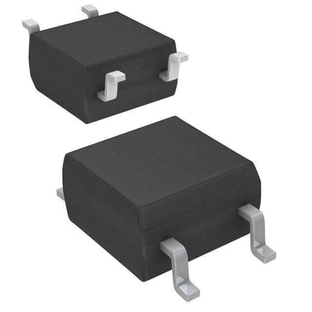
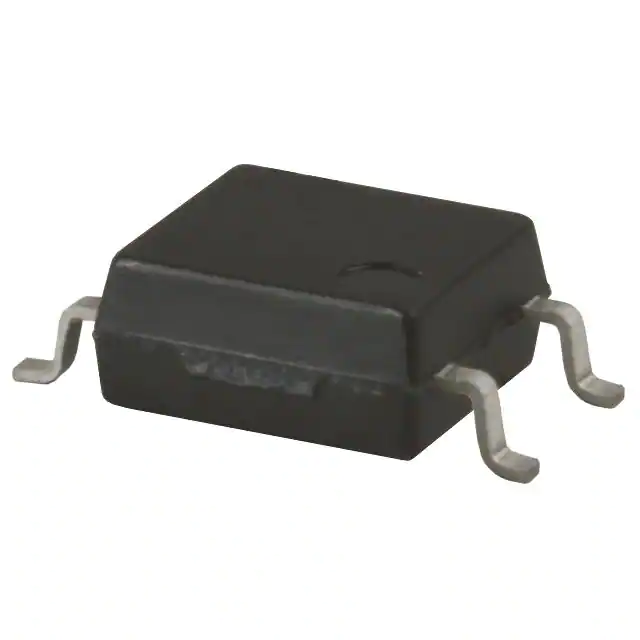
Toshiba Semiconductor and Storage TLP170AM(TPL,E
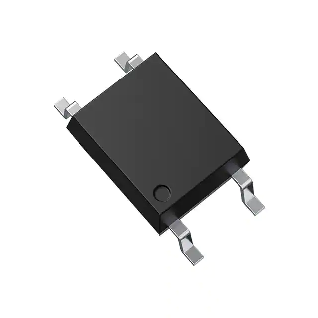
- Part No.:
- TLP170AM(TPL,E
- Manufacturer:
- Toshiba Semiconductor and Storage
- Category:
- Solid State Relays (SSR)
- Package:
- 6-SOP (0.179", 4.55mm), 4 Leads
- Datasheet:
-
 TLP170AM(TPL,E.pdf
- Description:
- SSR RELAY SPST-NO 700MA 0-60V
- Quantity:
- Payment:

- Shipping:

Inventory:13,543
Please send an inquiry. Send us your inquiry, and we will respond immediately.
Product details
Overview
TLP170AM(TPL,E from Toshiba Electronic Devices & Storage Corporation is a halogen-free, normally-open photorelay in a 4-pin SO6 (11-4M1S) package, integrating an infrared LED and photo-MOSFET. It delivers 700 mA max ON-state current, 0.3 Ω max ON-resistance, and 3750 Vrms isolation-designed for high-current On/Off control in PLC I/O modules and mechanical relay replacements.
For engineers reviewing the TLP170AM(TPL,E datasheet, TLP170AM(TPL,E pinout, TLP170AM(TPL,E application, or TLP170AM(TPL,E equivalent, key selection criteria include OFF-state voltage rating (60 V min), trigger LED current (1 mA max), thermal derating of output current, and VDE-compliant variants for safety-critical industrial interfaces.
Technical Context
The TLP170AM(TPL,E implements a single-pole, normally-open (1-Form-A) solid-state switch architecture using optically coupled GaAs LED and silicon MOSFET. Its internal two-terminal configuration shorts pins 1&3 (LED anode/cathode pair) and pins 4&6 (MOSFET drain terminals), enabling bidirectional load switching with galvanic isolation.
It operates within –40°C to +85°C ambient, supports up to 48 V supply voltage, and exhibits 3 ms typical turn-on time and 0.4 ms typical turn-off time at 20 V, 2 mA LED drive-optimized for low-power control of resistive and inductive loads in factory automation and security system I/O stages.
Key Specifications
| Parameter | Value and Actual Design Meaning |
|---|---|
| Isolation Voltage | 3750 Vrms min - meets UL 1577, CSA 5A, and EN 60747-5-5 (with V4 option) for reinforced insulation in industrial control systems |
| ON-State Current | 700 mA max - supports direct switching of solenoids, indicator lamps, and small motors without external drivers |
| ON-Resistance | 0.3 Ω max - limits conduction loss to ≤147 mW at 700 mA, reducing thermal stress in compact PCB layouts |
| Trigger LED Current | 1 mA max - enables direct interface with low-drive MCU GPIOs or logic buffers without series resistor recalculations |
| OFF-State Voltage | 60 V min - sustains transient overvoltage in 24 V DC control circuits and withstands back-EMF from inductive loads |
| Turn-On/Off Time | 6 ms / 1 ms max - ensures deterministic timing for synchronized I/O scanning in PLC scan cycles |
| Creepage/Clearance | 5.0 mm min - satisfies IPC-2221B spacing requirements for Pollution Degree 2 environments |
Pinout & Package
Package: 4-pin SO6 (TOSHIBA designation 11-4M1S), surface-mount, halogen-free epoxy resin, 0.1 g typical weight, 5.0 mm creepage/clearance, 0.2 mm internal isolation thickness.
| Pin/Terminal | Circuit Role | Design Meaning |
|---|---|---|
| 1 & 3 (shorted) | LED Anode & Cathode | Input side: bidirectional LED connection; requires series current-limiting resistor referenced to control logic rail |
| 4 & 6 (shorted) | MOSFET Drain | Output side: dual-drain configuration provides symmetrical current path for AC/DC load switching |
Key Features
| Feature | Design Value |
|---|---|
| Normally-open (1-Form-A) topology | Ensures fail-safe de-energization of connected loads during LED open-circuit or power loss |
| Halogen-free packaging | Complies with IEC 61249-2-21 and JEDEC J-STD-020 for lead-free reflow compatibility and RoHS alignment |
| Low trigger threshold (1 mA max) | Reduces MCU I/O loading and eliminates need for dedicated LED driver ICs in space-constrained designs |
| High isolation reliability | 3750 Vrms withstand and ≥10¹⁰ Ω isolation resistance enable use in SELV and functional insulation barriers per IEC 61800-5-1 |
| VDE-certifiable variant | V4 option satisfies EN 60747-5-5 for applications requiring certified safety isolation in EU machinery directives |
Applications
| Security Systems | Factory Automation (FA) |
|---|---|
Use Scenario: Isolated door lock actuation and alarm zone monitoring in access control panels. IC Role / Device Role / Timing Role: Solid-state relay replacing electromechanical contacts to eliminate bounce, wear, and EMI in 12–24 V DC lock circuits. Use Value: 700 mA current capacity drives solenoid locks directly; 3750 Vrms isolation prevents ground-loop interference between panel CPU and field wiring. | Use Scenario: Digital output module for PLC racks controlling pneumatic valves and conveyor motor starters. IC Role / Device Role / Timing Role: Output stage isolator providing galvanic separation between controller logic and 24 V DC field power. Use Value: 1 mA max trigger current simplifies interface with FPGA or ASIC I/O banks; 6 ms max turn-on ensures deterministic response within 10 ms scan cycles. |
| Measuring Instruments | I/O Interface Boards |
Use Scenario: Range switching and signal path selection in multimeters and data acquisition front-ends. IC Role / Device Role / Timing Role: Precision analog switch isolator routing test signals while blocking common-mode noise from measurement circuits. Use Value: 0.3 Ω max RON introduces <0.1% gain error at 100 mA; 100 pF max output capacitance preserves bandwidth in 100 kHz signal paths. | Use Scenario: Isolated digital input/output expansion for embedded controllers in industrial gateways. IC Role / Device Role / Timing Role: Bidirectional level-shifting and fault-isolation barrier between host processor and field-side peripherals. Use Value: Dual-drain (pins 4&6) configuration allows shared return path design; SO6 footprint minimizes board area vs. through-hole relays. |
Equivalent & Alternatives
The following parts are listed as comparable options for similar photorelay applications.
| Alternative Part | Technical Difference | Application Difference | Selection Advice |
|---|---|---|---|
| PVG612A | Higher 1.2 A max ION, but 0.5 Ω max RON; 5000 Vrms isolation; 6-pin DIP package | Requires larger PCB area; better suited for higher-current 48 V systems with stricter leakage requirements | Select PVG612A when >700 mA load current or >5000 Vrms isolation is mandatory; not drop-in due to pin count and layout change |
| TLP3547 | Same SO6 package; 600 mA max ION, 0.4 Ω max RON; 5000 Vrms isolation; VDE-certified standard version | Lower current rating; tighter RON tolerance; pre-certified for EN 60747-5-5 without V4 option | Choose TLP3547 if VDE compliance is required out-of-box and 600 mA suffices; same footprint enables layout reuse |
Compared with PVG612A and TLP3547, the TLP170AM(TPL,E offers optimal balance of 700 mA current drive, ultra-low 0.3 Ω RON, and compact SO6 footprint-making it preferred for cost-sensitive, space-constrained 24 V industrial I/O where VDE certification is optional.
Availability
TLP170AM(TPL,E is available at Aetrix Electronics and suitable for programmable logic controllers (PLCs), security system control panels, and factory automation I/O modules requiring stable component supply, long-term lifecycle support, and RoHS-compliant sourcing.
Supply support for TLP170AM(TPL,E includes scheduled delivery planning, volume procurement assistance, BOM continuity management, traceable sourcing, and lifecycle availability coordination for OEM customers, industrial embedded developers, connected-device designers, and electronics production programs.
Manufacturer
Toshiba Electronic Devices & Storage Corporation designs and manufactures discrete semiconductors, power devices, and optoelectronics for industrial, automotive, and consumer applications.
The TLP170AM(TPL,E belongs to Toshiba's photorelay product line, engineered specifically for solid-state replacement of mechanical relays in industrial control, offering high reliability, low drive requirements, and safety-certifiable isolation.
FAQ
What is the maximum continuous ON-state current rating for the TLP170AM(TPL,E?
The TLP170AM(TPL,E has a maximum continuous ON-state current rating of 700 mA at Ta = 25°C. Derating applies above 25°C: –8.3 mA/°C. This rating enables direct driving of solenoids, lamps, and small actuators without external amplification, provided heatsinking and PCB copper area meet thermal guidelines in the Toshiba Semiconductor Reliability Handbook.
Does the TLP170AM(TPL,E support AC load switching?
Yes, the TLP170AM(TPL,E supports AC load switching because its output consists of back-to-back MOSFETs configured as a bidirectional switch (pins 4 and 6 shorted). The 60 V minimum OFF-state voltage and 0.3 Ω max ON-resistance allow safe operation with 24 V AC control signals and resistive/inductive AC loads up to the 700 mA current limit.
What is the pin configuration and internal connection of the TLP170AM(TPL,E?
The TLP170AM(TPL,E uses a 4-pin SO6 package (11-4M1S) with internal shorting: pins 1 and 3 form the LED anode–cathode pair, while pins 4 and 6 are internally connected as the MOSFET drain terminals. This two-terminal structure simplifies PCB layout and enables symmetrical current flow in either direction across the output.
Is the TLP170AM(TPL,E halogen-free and RoHS compliant?
Yes, the TLP170AM(TPL,E is halogen-free per Toshiba's definition (Br/Cl/Sb ≤ 0.09 wt%, total Br+Cl ≤ 0.15 wt%) and RoHS compliant (Directive 2011/65/EU). The "E" suffix in the part number explicitly denotes RoHS-compatibility; full compliance documentation is available in Toshiba's environmental reports and material declarations for TLP170AM(TPL,E.
What safety certifications does the TLP170AM(TPL,E hold?
The TLP170AM(TPL,E is UL-recognized (UL 1577, File No. E67349) and cUL-recognized (CSA 5A, File No. E67349). For VDE certification to EN 60747-5-5, the V4 option variant (e.g., TLP170AM(V4,E) must be selected-the base TLP170AM(TPL,E does not carry VDE approval.
TLP170AM(TPL,E Specifications
- Product attributes
- Attribute value
- Manufacturer:
- Toshiba Semiconductor and Storage
- Series:
- TLP170AM
- Packaging:
- Tape & Reel (TR)
- Product Status:
- Active
- Mounting Type:
- Surface Mount
- Circuit:
- SPST-NO (1 Form A)
- Output Type:
- AC, DC
- Voltage - Input:
- 1.27VDC
- Voltage - Load:
- 0 V ~ 60 V
- Load Current:
- 700 mA
- On-State Resistance (Max):
- 300 mOhms
- Termination Style:
- Gull Wing
- Operating Temperature:
- -55°C ~ 125°C
- Supplier Device Package:
- 6-SOP (2.54mm)
- Approval Agency:
- cUL, UL, VDE
- Grade:
- -
- Qualification:
- -
TLP170AM(TPL,E FAQ
1.How can I place an order for TLP170AM(TPL,E through Aetrix?
Please submit a Request for Quotation (RFQ) for TLP170AM(TPL,E on Aetrix. Our sales agent will provide a competitive quotation and guide you through the order confirmation once you accept the terms.
2.Are the price and stock information for TLP170AM(TPL,E reliable?
The price and inventory of TLP170AM(TPL,E are updated periodically and may fluctuate due to market conditions. Stock and pricing data are typically refreshed every 24 hours. Quotation validity for TLP170AM(TPL,E is usually 5 days.
3.What payment methods are accepted for TLP170AM(TPL,E?
We accept Wire Transfer, PayPal, Credit Card, Western Union, MoneyGram, and Escrow for TLP170AM(TPL,E transactions.
Note: Certain payment methods may incur a processing fee.
4.How is shipping managed for TLP170AM(TPL,E?
TLP170AM(TPL,E orders can be shipped via leading logistics carriers, including DHL, UPS, FedEx, TNT, or Registered Mail.
Once your TLP170AM(TPL,E order is processed, you will receive an email with the shipment details and tracking number.
Note: Tracking information may take up to 24 hours to appear. Express delivery typically takes 3–5 business days.
5.How can I obtain technical support or documentation for TLP170AM(TPL,E?
For technical support, including TLP170AM(TPL,E datasheets, pinout diagrams, or application guidance, please contact our engineering support team. They can provide detailed documentation and assistance for your TLP170AM(TPL,E requirements.
6.How does Aetrix verify that TLP170AM(TPL,E is sourced from the original manufacturer or authorized distributors?
All TLP170AM(TPL,E products on Aetrix are procured from qualified distributors and authorized channels. Our dedicated quality assurance team conducts strict verification, including traceability checks and, if necessary, third-party testing. This ensures that TLP170AM(TPL,E meets industry standards.
7.What is the process for return or replacement of TLP170AM(TPL,E?
All TLP170AM(TPL,E units undergo pre-shipment inspection (PSI). If there is an issue with TLP170AM(TPL,E, returns or replacements are accepted under the following conditions:
1.Quantity discrepancies, incorrect items, or visible external defects (such as breakage or corrosion), acknowledged by Aetrix.
2.The issue is reported within 90 days of delivery.
3.The TLP170AM(TPL,E part is unused and in its original packaging.
Return procedure for TLP170AM(TPL,E:
1.Submit a request within 90 days.
2.Obtain a Return Material Authorization (RMA) from Aetrix.
TLP170AM(TPL,E Tags
.jpg)
-
G3VM-21UR11(TR05)
Omron Electronics Inc-EMC Div
-
G3VM-61VY3(TR05)
Omron Electronics Inc-EMC Div
-
CPC1017NTR
Littelfuse Inc.
-
CPC1017N
Littelfuse Inc.
-
CPC1006N
Littelfuse Inc.
-
VO1400AEFTR
Vishay Semiconductor Opto Division
-
CPC1006NTR
Littelfuse Inc.
-
TLP175A(TPL,E
Toshiba Semiconductor and Storage
-
CPC1002NTR
Littelfuse Inc.
-
AQY280S
Panasonic Electric Works
-
CPC1117NTR
Littelfuse Inc.
-
CPC1106NTR
Littelfuse Inc.
Tech Hub

Counterfeit components can hide behind convincing markings and passing basic function tests. This engineering reference covers source traceability, external inspection, X-ray, XRF, electrical testing, …

A practical engineering and sourcing framework covering lifecycle verification, lifetime-buy calculations, replacement qualification, supplier checks and counterfeit-risk controls.

TTL and CMOS logic families differ in thresholds, loading, output drive, power and timing. This engineering guide compares 74HC and 74HCT, calculates noise margins and checks 3.3 V/5 V compatibility.

A practical engineering guide to 3.3V and 5V logic compatibility, input thresholds, resistor dividers, translator ICs, MOSFET level shifting, I2C pull-ups, timing limits and power-sequencing risks.

The 74HC595 uses push-pull logic outputs, while the TPIC6B595 uses 50 V open-drain DMOS sinks for higher-power loads. This guide compares timing, current limits, 3.3 V interfacing, load wiring, thermal…

The 74HC595 converts serial data into eight stable parallel outputs. This guide covers pin functions, shift and storage timing, OE and MR behavior, drive-current limits, cascading, voltage compatibilit…

A technical comparison of level-sensitive latches and edge-triggered flip-flops, covering timing windows, setup and hold limits, master–slave operation, time borrowing, race-through, HDL inference and…

A D latch stores one bit while Enable controls when data can pass. This reference covers gate-level operation, truth tables, transparency, setup and hold timing, LE versus OE, common ICs and practical …

An SR latch stores one bit through cross-coupled feedback. This engineering reference covers NOR and NAND implementations, truth tables, forbidden-state recovery, gated operation, switch debouncing, fa…

Latch circuits retain one bit through feedback. This technical reference covers SR and D latches, truth tables, transparency, timing limits, latch-versus-flip-flop behavior, applications and common log…


