
 My Inquiry
 My Account


Toshiba Semiconductor and Storage TLP5772(D4,E
- Part No.:
- TLP5772(D4,E
- Manufacturer:
- Toshiba Semiconductor and Storage
- Category:
- Logic Output Optoisolators
- Package:
- 6-SOIC (0.295", 7.50mm Width)
- Datasheet:
-
 TLP5772(D4,E.pdf
- Description:
- OPTOISO 5KV 1CH PSH PULL 6SO
- Quantity:
- Payment:

- Shipping:

Inventory:118
Please send an inquiry. Send us your inquiry, and we will respond immediately.
Product details
Overview
TLP5772(D4,E) from Toshiba Electronic Devices & Storage Corporation is a reinforced-insulation photocoupler integrating an infrared LED and high-speed photodetector in a 6-pin SO6L package. It delivers ±2.5 A peak output current, 150 ns max propagation delay, ±35 kV/µs common-mode transient immunity, and operates across -40°C to +110°C - enabling direct microcontroller drive in compact motor drivers and industrial inverters.
For engineers reviewing the TLP5772(D4,E) datasheet, TLP5772(D4,E) pinout, TLP5772(D4,E) application, or TLP5772(D4,E) equivalent, key selection criteria include its VDE-approved reinforced insulation (EN IEC 60747-5-5), rail-to-rail totem-pole output, low 2 mA max threshold input current, and 5000 Vrms isolation voltage for safety-critical gate driving.
Technical Context
The TLP5772(D4,E) implements a monolithic photo-IC architecture with internal Faraday shielding, enabling guaranteed ±35 kV/µs common-mode transient immunity. Its totem-pole output stage supports rail-to-rail switching between VCC (10–30 V) and GND, delivering ±2.5 A peak current into capacitive loads.
This device operates as a logic-output isolator with defined truth table behavior: LED ON drives output high (VO ≈ VCC); LED OFF drives output low (VO ≈ 0 V). It requires a 1 µF bypass capacitor between pins 6 (VCC) and 4 (GND) to stabilize the high-gain amplifier and ensure reliable switching at up to 50 kHz.
Key Specifications
| Parameter | Value and Actual Design Meaning |
|---|---|
| Isolation Voltage | 5000 Vrms min - meets reinforced insulation requirements for industrial safety standards including UL 1577 and EN IEC 60747-5-5. |
| Output Peak Current | ±2.5 A max - enables direct driving of IGBT/MOSFET gates without external buffer stages in motor control applications. |
| Propagation Delay | 150 ns max - ensures precise timing alignment in high-frequency PWM systems like AC servos and inverters. |
| Common-Mode Transient Immunity | ±35 kV/µs min - suppresses noise-induced false triggering in noisy power electronics environments. |
| Threshold Input Current | 2 mA max - allows direct connection to MCU GPIOs without series resistor adjustment or level-shifting circuitry. |
| Supply Voltage Range | 10–30 V - compatible with standard industrial DC bus voltages and supports wide-range operation under load variation. |
| Operating Temperature | -40°C to +110°C - qualified for use in enclosed industrial enclosures and high-ambient-temperature motor drive cabinets. |
Pinout & Package
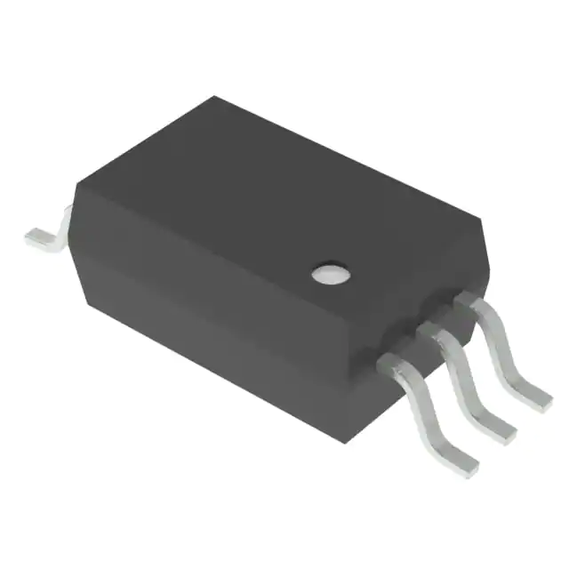
Package: 6-pin SO6L (TOSHIBA package code 11-4N1A), surface-mount, creepage/clearance ≥ 8.0 mm, isolation thickness ≥ 0.4 mm, height ≤ 2.3 mm.
| Pin/Terminal | Circuit Role | Design Meaning |
|---|---|---|
| 1: Anode | LED anode input | Connects to current-limited MCU output or driver; forward current up to 8 mA. |
| 2: N.C. | No connection | Internally unconnected; must remain floating - no PCB trace or component attachment. |
| 3: Cathode | LED cathode return | Completes LED current path; typically tied to MCU ground or open-collector driver sink. |
| 4: GND | Detector ground reference | Return path for output stage and bypass capacitor; must be low-impedance local ground plane. |
| 5: VO (Output) | Logic-level output terminal | Rail-to-rail totem-pole output; sinks or sources up to ±2.5 A; connects directly to gate driver input. |
| 6: VCC | Detector supply input | Power input for photodetector IC; requires 1 µF ceramic bypass capacitor to pin 4 for stability. |
Key Features
| Feature | Design Value |
|---|---|
| Reinforced insulation certification | VDE-approved per EN IEC 60747-5-5 (Option D4), UL 1577, and CSA Component Acceptance - enables single-component safety compliance in PV inverters and servo drives. |
| Faraday shield integration | Guarantees ±35 kV/µs CMTI - eliminates need for external noise suppression in high-dV/dt motor control circuits. |
| Bufferless microcontroller interface | 2 mA max IF(L/H) threshold - removes external current-setting resistors and simplifies PCB layout in space-constrained designs. |
| Rail-to-rail totem-pole output | VO swings from GND to VCC (10–30 V) - provides full logic swing for robust gate drive signal integrity without level shifters. |
| Compact SO6L footprint | 50% smaller than legacy 8-pin DIP - reduces PCB area by >30% while maintaining creepage/clearance for safety certification. |
Applications
| Photovoltaic Power Conditioning | AC Servo Drives |
|---|---|
|
Use Scenario: Isolating control signals between DSP-based MPPT controller and high-voltage DC-AC inverter stage in solar string inverters. IC Role / Device Role / Timing Role: Gate drive signal isolator for IGBT half-bridge modules, transmitting PWM with <150 ns timing fidelity. Use Value: Reinforced 5000 Vrms isolation prevents ground loop faults and meets IEC 62109 safety requirements for PV systems. |
Use Scenario: Transmitting position-loop PWM commands from motion controller to three-phase inverter in CNC machine servos. IC Role / Device Role / Timing Role: High-CMTI signal isolator ensuring accurate gate timing despite rapid bus voltage transients during commutation. Use Value: ±35 kV/µs immunity prevents false turn-on/turn-off of motor phase legs under high di/dt conditions. |
| Compact Motor Drivers | Industrial Inverters |
|
Use Scenario: Enabling space-efficient BLDC motor control in HVAC blowers and pump modules where board real estate is constrained. IC Role / Device Role / Timing Role: Logic-output photocoupler replacing opto-TRIACs or discrete buffer-isolator combos in 3-phase gate driver interfaces. Use Value: SO6L package reduces mounting area by 50% vs. DIP-8 while maintaining full safety certification and ±2.5 A drive capability. |
Use Scenario: Isolating gate signals in medium-voltage VFDs used in conveyor systems and compressors operating at 400–690 VAC. IC Role / Device Role / Timing Role: Safety-certified isolator interfacing FPGA-based PWM generator with isolated gate driver ICs. Use Value: VDE EN IEC 60747-5-5 qualification (D4 option) satisfies mandatory reinforced insulation for IEC 61800-5-1 compliance. |
Equivalent & Alternatives
The following parts are listed as comparable options for similar logic-output photocoupler applications.
| Alternative Part | Technical Difference | Application Difference | Selection Advice |
|---|---|---|---|
| TLP5774(D4,E) | Dual-channel version in same SO6L package; shares identical electrical specs per channel but doubles channel count. | Used where two independent isolated gate drives are required (e.g., half-bridge high/low side) without increasing board area. | Select TLP5774(D4,E) only when dual-channel functionality is needed; not pin-compatible with TLP5772(D4,E) due to different pin assignment. |
| SI87xxAC-B-IS | Silicon Labs digital isolator; 5 kVrms isolation, 100 Mbps data rate, but lacks integrated gate drive strength (max 10 mA output). | Requires external gate driver IC (e.g., UCC27531) to achieve ±2.5 A; adds component count and layout complexity. | Choose SI87xxAC-B-IS only if system demands higher data rate or lower propagation delay (<50 ns); not a functional replacement for direct gate drive. |
Compared with TLP5772(D4,E), the TLP5774(D4,E) offers dual-channel integration in identical footprint but requires PCB redesign for pin mapping, while the SI87xxAC-B-IS provides faster digital isolation but cannot replace TLP5772(D4,E)'s integrated ±2.5 A gate drive capability without added components.
Availability
TLP5772(D4,E) is available at Aetrix Electronics and suitable for photovoltaic power conditioning systems, AC servo drives, and industrial inverters requiring stable component supply with VDE-reinforced insulation certification and high CMTI performance.
Supply support for TLP5772(D4,E) includes scheduled delivery planning, volume procurement assistance, BOM continuity management, traceable sourcing, and lifecycle availability coordination for OEM customers, industrial embedded developers, connected-device designers, and electronics production programs.
Manufacturer
Toshiba Electronic Devices & Storage Corporation designs and manufactures high-reliability semiconductor components, with global leadership in optocouplers, power devices, and storage solutions.
The TLP577x series targets industrial power electronics, delivering reinforced-isolation gate drivers optimized for motor control, renewable energy, and factory automation applications where safety, noise immunity, and compactness are critical.
FAQ
What safety certifications apply to the TLP5772(D4,E)?
The TLP5772(D4,E) carries VDE approval per EN IEC 60747-5-5 (Option D4), UL recognition per UL 1577 (File E67349), and cUL certification per CSA Component Acceptance Service No. 5A File E67349. These confirm compliance with reinforced insulation requirements for industrial equipment operating up to 5000 Vrms working voltage. The "(D4)" suffix explicitly denotes VDE qualification.
Does the TLP5772(D4,E) require an external bypass capacitor?
Yes - a 1 µF ceramic capacitor must be placed between pin 6 (VCC) and pin 4 (GND), located within 1 cm of both pins. This stabilizes the internal high-gain amplifier and prevents oscillation or erratic switching. Omission causes unreliable output behavior, especially at high frequencies or elevated temperatures. The TLP5772(D4,E) datasheet mandates this in Section 6 and Section 9.
Can the TLP5772(D4,E) directly drive IGBT gates without a buffer stage?
Yes - the TLP5772(D4,E) delivers ±2.5 A peak output current and rail-to-rail VO swing (0 V to VCC), enabling direct connection to IGBT or MOSFET gates in motor drives and inverters. Its 2 mA max threshold input current allows direct MCU GPIO drive, eliminating external buffers. This capability is confirmed in Sections 2, 3, and 10 of the TLP5772(D4,E) datasheet.
What is the meaning of "(D4,E)" in the TLP5772(D4,E) part number?
The "(D4,E)" suffix indicates two specific qualifications: "D4" designates compliance with EN IEC 60747-5-5 Option D4 for reinforced insulation, verified by VDE; "E" denotes RoHS-compliant, lead-free construction. This exact marking appears in Toshiba's Ordering Information table (Section 18) and confirms the unit meets both safety and environmental requirements for industrial deployment.
How does the TLP5772(D4,E) achieve ±35 kV/µs common-mode transient immunity?
The TLP5772(D4,E) integrates an internal Faraday shield between input and output die, physically blocking capacitive coupling of fast transients. This structure is specified in Section 2 and validated in Section 12 (CMH/CML test conditions), guaranteeing ±35 kV/µs minimum immunity - a value measured under 1000 Vp-p common-mode step with defined load conditions, not extrapolated or estimated.
TLP5772(D4,E Specifications
- Product attributes
- Attribute value
- Manufacturer:
- Toshiba Semiconductor and Storage
- Series:
- -
- Package/Case:
- 6-SOIC (0.295", 7.50mm Width)
- Packaging:
- Tube
- Product Status:
- Active
- Number of Channels:
- 1
- Inputs - Side 1/Side 2:
- 1/0
- Voltage - Isolation:
- 5000Vrms
- Common Mode Transient Immunity (Min):
- 35kV/µs
- Input Type:
- DC
- Output Type:
- Push-Pull, Totem Pole
- Current - Output / Channel:
- -
- Data Rate:
- -
- Propagation Delay tpLH / tpHL (Max):
- 150ns, 150ns
- Rise / Fall Time (Typ):
- 15ns, 8ns
- Voltage - Forward (Vf) (Typ):
- 1.65V
- Current - DC Forward (If) (Max):
- 8mA
- Voltage - Supply:
- 10V ~ 30V
- Grade:
- -
- Qualification:
- -
- Operating Temperature:
- -40°C ~ 110°C
- Mounting Type:
- Surface Mount
- Supplier Device Package:
- 6-SO
TLP5772(D4,E FAQ
1.How can I place an order for TLP5772(D4,E through Aetrix?
Please submit a Request for Quotation (RFQ) for TLP5772(D4,E on Aetrix. Our sales agent will provide a competitive quotation and guide you through the order confirmation once you accept the terms.
2.Are the price and stock information for TLP5772(D4,E reliable?
The price and inventory of TLP5772(D4,E are updated periodically and may fluctuate due to market conditions. Stock and pricing data are typically refreshed every 24 hours. Quotation validity for TLP5772(D4,E is usually 5 days.
3.What payment methods are accepted for TLP5772(D4,E?
We accept Wire Transfer, PayPal, Credit Card, Western Union, MoneyGram, and Escrow for TLP5772(D4,E transactions.
Note: Certain payment methods may incur a processing fee.
4.How is shipping managed for TLP5772(D4,E?
TLP5772(D4,E orders can be shipped via leading logistics carriers, including DHL, UPS, FedEx, TNT, or Registered Mail.
Once your TLP5772(D4,E order is processed, you will receive an email with the shipment details and tracking number.
Note: Tracking information may take up to 24 hours to appear. Express delivery typically takes 3–5 business days.
5.How can I obtain technical support or documentation for TLP5772(D4,E?
For technical support, including TLP5772(D4,E datasheets, pinout diagrams, or application guidance, please contact our engineering support team. They can provide detailed documentation and assistance for your TLP5772(D4,E requirements.
6.How does Aetrix verify that TLP5772(D4,E is sourced from the original manufacturer or authorized distributors?
All TLP5772(D4,E products on Aetrix are procured from qualified distributors and authorized channels. Our dedicated quality assurance team conducts strict verification, including traceability checks and, if necessary, third-party testing. This ensures that TLP5772(D4,E meets industry standards.
7.What is the process for return or replacement of TLP5772(D4,E?
All TLP5772(D4,E units undergo pre-shipment inspection (PSI). If there is an issue with TLP5772(D4,E, returns or replacements are accepted under the following conditions:
1.Quantity discrepancies, incorrect items, or visible external defects (such as breakage or corrosion), acknowledged by Aetrix.
2.The issue is reported within 90 days of delivery.
3.The TLP5772(D4,E part is unused and in its original packaging.
Return procedure for TLP5772(D4,E:
1.Submit a request within 90 days.
2.Obtain a Return Material Authorization (RMA) from Aetrix.
TLP5772(D4,E Tags

-
6N137
Lite-On Inc.
-
6N137S
Lite-On Inc.
-
6N137S-TA1
Lite-On Inc.
.JPG)
-
TLP2362(TPR,E
Toshiba Semiconductor and Storage

-
H11L1M
onsemi
-
TLP2355(TPL,E
Toshiba Semiconductor and Storage
-
TLP2361(TPL,E
Toshiba Semiconductor and Storage
-
TLP2358(TPL,E)
Toshiba Semiconductor and Storage
-
H11L1SR2M
onsemi
-
TLP2361(V4-TPL,E
Toshiba Semiconductor and Storage
.JPG)
-
H11L1S(TA)
Everlight Electronics Co Ltd
-
H11L1SM
onsemi
Tech Hub

Counterfeit components can hide behind convincing markings and passing basic function tests. This engineering reference covers source traceability, external inspection, X-ray, XRF, electrical testing, …

A practical engineering and sourcing framework covering lifecycle verification, lifetime-buy calculations, replacement qualification, supplier checks and counterfeit-risk controls.

TTL and CMOS logic families differ in thresholds, loading, output drive, power and timing. This engineering guide compares 74HC and 74HCT, calculates noise margins and checks 3.3 V/5 V compatibility.

A practical engineering guide to 3.3V and 5V logic compatibility, input thresholds, resistor dividers, translator ICs, MOSFET level shifting, I2C pull-ups, timing limits and power-sequencing risks.

The 74HC595 uses push-pull logic outputs, while the TPIC6B595 uses 50 V open-drain DMOS sinks for higher-power loads. This guide compares timing, current limits, 3.3 V interfacing, load wiring, thermal…

The 74HC595 converts serial data into eight stable parallel outputs. This guide covers pin functions, shift and storage timing, OE and MR behavior, drive-current limits, cascading, voltage compatibilit…

A technical comparison of level-sensitive latches and edge-triggered flip-flops, covering timing windows, setup and hold limits, master–slave operation, time borrowing, race-through, HDL inference and…

A D latch stores one bit while Enable controls when data can pass. This reference covers gate-level operation, truth tables, transparency, setup and hold timing, LE versus OE, common ICs and practical …

An SR latch stores one bit through cross-coupled feedback. This engineering reference covers NOR and NAND implementations, truth tables, forbidden-state recovery, gated operation, switch debouncing, fa…

Latch circuits retain one bit through feedback. This technical reference covers SR and D latches, truth tables, transparency, timing limits, latch-versus-flip-flop behavior, applications and common log…


