
 My Inquiry
 My Account


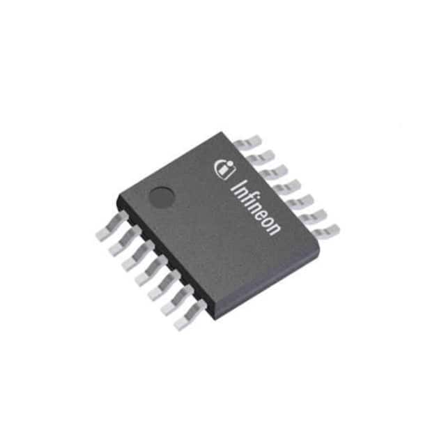
Infineon Technologies TLS4125D0EPV50XUMA1
- Part No.:
- TLS4125D0EPV50XUMA1
- Manufacturer:
- Infineon Technologies
- Package:
- 14-PowerTSSOP (0.154", 3.90mm Width)
- Datasheet:
-
 TLS4125D0EPV50XUMA1.pdf
- Description:
- IC REG BUCK 5V 2.5A TSDSO-14-5
- Quantity:
- Payment:

- Shipping:

Inventory:2,679
Please send an inquiry. Send us your inquiry, and we will respond immediately.
Product details
Overview
TLS4125D0EPV50 from Infineon Technologies is a 2.8 MHz synchronous step-down DC-DC regulator with 2.5 A output current, fixed 5 V output voltage, ±1.5% feedback accuracy in PWM mode, and integrated high-side/low-side MOSFETs. Designed for automotive battery cranking scenarios, it operates across 3.7 V–35 V input and supports 100% duty cycle.
For engineers reviewing the TLS4125D0EPV50 datasheet, TLS4125D0EPV50 pinout, TLS4125D0EPV50 application, or TLS4125D0EPV50 equivalent, key selection factors include its AEC-Q100 qualification, spread spectrum EMI reduction, PFM light-load efficiency, ultra-low 1 µA shutdown current, and reset output with undervoltage/overvoltage monitoring.
Technical Context
This buck regulator uses peak-current-mode PWM control with automatic transition to PFM at light loads, enabling high efficiency across wide load ranges. Its oscillator supports dual frequency bands (320–560 kHz or 1.6–2.8 MHz), external synchronization via SYNC pin, and spread spectrum modulation activated by SSON pin to reduce EMI peaks.
The device integrates soft-start ramp generation, active output discharge during disable, and a dedicated reset circuit with configurable delay and threshold via RT pin. Protection includes overcurrent, overload, input UVLO, overtemperature shutdown, and output UV/OV detection feeding an open-drain RO signal.
Key Specifications
| Parameter | Value and Actual Design Meaning |
|---|---|
| Output Current | 2.5 A continuous - supports automotive ECUs requiring stable 5 V rail under transient load steps. |
| Input Voltage Range | 3.7 V to 35 V - accommodates cold-crank (4.5 V) and load-dump (35 V) conditions per ISO 7637-2. |
| Output Voltage | Fixed 5 V ±1.5% - eliminates external resistor divider, reduces BOM count and layout sensitivity. |
| Switching Frequency | 2.8 MHz (default high-band) - enables compact 1.0 µH inductors and low-ESR ceramic capacitors. |
| Quiescent Current | 31 µA in PFM mode - extends battery life in always-on vehicle modules like telematics. |
| Shutdown Current | 1 µA typical - meets stringent automotive standby power budgets for infotainment head units. |
| Thermal Range | Tj = −40°C to +150°C - qualified for under-hood placement per AEC-Q100 Grade 0. |
Pinout & Package
Delivered in PG-TSDSO-14 exposed pad package with thermal enhancement for automotive under-hood operation. The exposed pad must be soldered to a large GND copper area for optimal thermal performance.
| Pin/Terminal | Circuit Role | Design Meaning |
|---|---|---|
| 1 FREQ | Frequency selection input | Resistor-to-GND sets low-band (320–560 kHz); open sets default high-band (1.6–2.8 MHz). |
| 2 SYNC | External clock input | Accepts 320 kHz–2.8 MHz square wave for EMI-sensitive systems requiring deterministic switching timing. |
| 3 RO | Open-drain reset output | Asserts low when output UV/OV detected; requires external pull-up to enable microcontroller reset signaling. |
| 4 AGND | Analog ground reference | Separate low-noise ground return for feedback and internal references; must be star-connected to PGND. |
| 5 EN | Enable control input | Active-high logic with internal pull-down; compatible with 3.3 V or 5 V MCU GPIO without level shift. |
| 6,7 VS | Main supply input | Dual-pin configuration lowers impedance path for high di/dt transients; shorted on PCB for robustness. |
| 8,9 PGND | Power ground return | Dual-pin connection minimizes ground loop inductance; requires direct low-inductance trace to input capacitor. |
| 10,11 SW | Switch node | High dv/dt node connecting to inductor; dual pins reduce parasitic inductance and improve EMI behavior. |
| 12 SSON | Spread spectrum enable | High enables frequency dithering; reduces peak radiated emissions without affecting regulation stability. |
| 13 RT | Reset configuration | Resistor-to-GND sets reset delay and UV threshold; open or grounded selects factory defaults. |
| 14 FB | Feedback input | Direct connection to output capacitor; senses 5 V output without external divider due to internal reference. |
Key Features
| Feature | Design Value |
|---|---|
| Integrated power stage | High-side and low-side MOSFETs co-optimized for 2.5 A, eliminating external gate drivers and reducing layout complexity. |
| 100% duty cycle operation | Maintains regulation down to 3.7 V input - critical for engine start-up when battery dips below 5 V. |
| Active output discharge | Internally discharges output capacitor when disabled - prevents residual voltage from interfering with downstream logic sequencing. |
| Integrated compensation | Type II compensation network embedded - removes need for external RC network, saving board space and tuning effort. |
| Reset with UV/OV monitoring | Dedicated RO signal asserts on output deviation beyond ±7% window - provides fail-safe indication for safety-critical ECUs. |
Applications
| Body Control Module | ADAS Camera Power Supply |
|---|---|
|
Use Scenario: Powering microcontrollers, CAN transceivers, and sensors in door modules and lighting controllers. IC Role / Device Role / Timing Role: Primary 5 V system rail regulator with AEC-Q100 reliability and cranking support. Use Value: 100% duty cycle maintains 5 V output during 4.5 V cold-crank events, preventing ECU brownout resets. |
Use Scenario: Providing clean, low-noise 5 V power to image sensor and ISP in forward-facing ADAS cameras. IC Role / Device Role / Timing Role: High-frequency buck converter minimizing inductor size while meeting CISPR 25 Class 5 EMI limits. Use Value: Spread spectrum modulation reduces peak radiated emissions by >10 dBµV/m at 100–500 MHz, easing EMC certification. |
| Infotainment Head Unit | Telematics Control Unit |
|
Use Scenario: Supplying 5 V to application processors, audio codecs, and display interfaces in center-stack systems. IC Role / Device Role / Timing Role: Always-on buck regulator with ultra-low 31 µA PFM quiescent current for parking mode operation. Use Value: Enables >30-day battery hold-up time in parked vehicle state without draining 12 V battery below restart threshold. |
Use Scenario: Delivering regulated 5 V to cellular modem, GNSS receiver, and secure element in connected car telematics units. IC Role / Device Role / Timing Role: Reset-capable power supply with RO signal tied to modem's RESET_IN for fault recovery. Use Value: Output UV/OV detection triggers RO assertion within 10 µs, allowing modem firmware to initiate safe shutdown before data corruption. |
Equivalent & Alternatives
The following parts are listed as comparable options for similar synchronous buck regulator applications.
| Alternative Part | Technical Difference | Application Difference | Selection Advice |
|---|---|---|---|
| TPS62933RGER | 3.6 V–36 V input, 3 A, 5 V fixed, 2.2 MHz, no spread spectrum, no reset output | Lacks RO signal and UV/OV monitoring - requires external supervisor IC for functional safety compliance | Preferred where EMI is less constrained and reset signaling is handled externally |
| MPQ4423AGL-AEC1 | 3.8 V–36 V input, 2.5 A, adjustable output, 2.2 MHz, no PFM mode, no integrated compensation | Requires external compensation and feedback resistors - increases design complexity and BOM count | Suitable when adjustable output voltage is needed and layout space allows external components |
Compared with TPS62933RGER and MPQ4423AGL-AEC1, TLS4125D0EPV50 uniquely integrates reset signaling, spread spectrum, and full compensation - reducing component count and simplifying AEC-Q100-compliant designs for fixed 5 V automotive rails.
Availability
TLS4125D0EPV50 is available at Aetrix Electronics and suitable for body control modules, ADAS camera systems, and infotainment head units requiring stable component supply with automotive-grade reliability and long-term lifecycle support.
Supply support for TLS4125D0EPV50 includes scheduled delivery planning, volume procurement assistance, BOM continuity management, traceable sourcing, and lifecycle availability coordination for OEM customers, industrial embedded developers, connected-device designers, and electronics production programs.
Manufacturer
Infineon Technologies is a German semiconductor manufacturer specializing in power management, automotive ICs, and security solutions, with global manufacturing and automotive qualification infrastructure.
This device belongs to the OPTIREG™ switcher product line, engineered specifically for automotive power conversion - emphasizing AEC-Q100 compliance, cranking resilience, EMI robustness, and functional safety features.
FAQ
What is the purpose of the RT pin?
The RT pin configures reset delay time and undervoltage threshold via an external resistor to GND. Connecting RT to GND selects default values: 200 ms delay and 4.65 V UV threshold. Leaving RT open disables reset functionality entirely, removing the need for external components when not required.
Can TLS4125D0EPV50 operate with input voltage below 5 V?
Yes - it supports 3.7 V minimum input and delivers full 2.5 A output down to that voltage. Crucially, it enables 100% duty cycle operation, maintaining regulation even during cold-crank events where battery voltage drops to 4.5 V or lower without dropping out of regulation.
How does spread spectrum modulation improve EMI performance?
Activating spread spectrum via the SSON pin dithers the switching frequency across ±10% of nominal value, spreading energy over a wider bandwidth. This reduces peak radiated emissions by up to 10 dBµV/m in the 100–500 MHz range, easing compliance with CISPR 25 Class 5 requirements for automotive electronics.
Is external compensation required for stable operation?
No - the TLS4125D0EPV50 integrates a complete Type II compensation network. No external capacitors or resistors are needed on the COMP pin (not exposed), simplifying layout and eliminating tuning iterations. Stability is guaranteed across all operating conditions specified in the datasheet.
TLS4125D0EPV50XUMA1 Specifications
- Product attributes
- Attribute value
- Manufacturer:
- Infineon Technologies
- Series:
- OPTIREG™
- Package/Case:
- 14-PowerTSSOP (0.154", 3.90mm Width)
- Packaging:
- Tape & Reel (TR)
- Product Status:
- Active
- Function:
- Step-Down
- Output Configuration:
- Positive
- Topology:
- Buck
- Output Type:
- Fixed
- Number of Outputs:
- 1
- Voltage - Input (Min):
- 3.7V
- Voltage - Input (Max):
- 35V
- Voltage - Output (Min/Fixed):
- 5V
- Voltage - Output (Max):
- -
- Current - Output:
- 2.5A
- Frequency - Switching:
- 2.8MHz
- Synchronous Rectifier:
- Yes
- Operating Temperature:
- -40°C ~ 150°C (TJ)
- Grade:
- Automotive
- Qualification:
- AEC-Q100
- Mounting Type:
- Surface Mount
- Supplier Device Package:
- PG-TSDSO-14-5
TLS4125D0EPV50XUMA1 FAQ
1.How can I place an order for TLS4125D0EPV50XUMA1 through Aetrix?
Please submit a Request for Quotation (RFQ) for TLS4125D0EPV50XUMA1 on Aetrix. Our sales agent will provide a competitive quotation and guide you through the order confirmation once you accept the terms.
2.Are the price and stock information for TLS4125D0EPV50XUMA1 reliable?
The price and inventory of TLS4125D0EPV50XUMA1 are updated periodically and may fluctuate due to market conditions. Stock and pricing data are typically refreshed every 24 hours. Quotation validity for TLS4125D0EPV50XUMA1 is usually 5 days.
3.What payment methods are accepted for TLS4125D0EPV50XUMA1?
We accept Wire Transfer, PayPal, Credit Card, Western Union, MoneyGram, and Escrow for TLS4125D0EPV50XUMA1 transactions.
Note: Certain payment methods may incur a processing fee.
4.How is shipping managed for TLS4125D0EPV50XUMA1?
TLS4125D0EPV50XUMA1 orders can be shipped via leading logistics carriers, including DHL, UPS, FedEx, TNT, or Registered Mail.
Once your TLS4125D0EPV50XUMA1 order is processed, you will receive an email with the shipment details and tracking number.
Note: Tracking information may take up to 24 hours to appear. Express delivery typically takes 3–5 business days.
5.How can I obtain technical support or documentation for TLS4125D0EPV50XUMA1?
For technical support, including TLS4125D0EPV50XUMA1 datasheets, pinout diagrams, or application guidance, please contact our engineering support team. They can provide detailed documentation and assistance for your TLS4125D0EPV50XUMA1 requirements.
6.How does Aetrix verify that TLS4125D0EPV50XUMA1 is sourced from the original manufacturer or authorized distributors?
All TLS4125D0EPV50XUMA1 products on Aetrix are procured from qualified distributors and authorized channels. Our dedicated quality assurance team conducts strict verification, including traceability checks and, if necessary, third-party testing. This ensures that TLS4125D0EPV50XUMA1 meets industry standards.
7.What is the process for return or replacement of TLS4125D0EPV50XUMA1?
All TLS4125D0EPV50XUMA1 units undergo pre-shipment inspection (PSI). If there is an issue with TLS4125D0EPV50XUMA1, returns or replacements are accepted under the following conditions:
1.Quantity discrepancies, incorrect items, or visible external defects (such as breakage or corrosion), acknowledged by Aetrix.
2.The issue is reported within 90 days of delivery.
3.The TLS4125D0EPV50XUMA1 part is unused and in its original packaging.
Return procedure for TLS4125D0EPV50XUMA1:
1.Submit a request within 90 days.
2.Obtain a Return Material Authorization (RMA) from Aetrix.
TLS4125D0EPV50XUMA1 Tags
-
TPS562201DDCR
Texas Instruments

-
MC34063ABD-TR
STMicroelectronics
-
TPS561201DDCR
Texas Instruments

-
MC33063ADR
Texas Instruments
-
MC34063ADR
Texas Instruments

-
TPS560200DBVR
Texas Instruments
-
AP3012KTR-G1
Diodes Incorporated
-
TLV61048DBVR
Texas Instruments
-
AZ34063UMTR-G1
Diodes Incorporated
-
TPS562200DDCR
Texas Instruments
-
AP62300TWU-7
Diodes Incorporated
-
MC34063EBD-TR
STMicroelectronics
Tech Hub

Operational amplifier guide covering op amp basics, feedback, ideal vs real op amps, common configurations, buffer circuits, offset, bias current, gain-bandwidth, slew rate, rail-to-rail limits and sel…

Jumper cables guide covering safe connection order, red and black clamp placement, final ground connection, cable gauge, length, clamp quality, copper vs CCA cables, jump starter comparison and battery…

LDO regulator guide covering low dropout voltage, power dissipation, thermal design, PSRR, output noise, capacitor stability, adjustable LDO circuits, LDO vs buck converter and datasheet selection chec…

Conditional Access Module guide covering CAM meaning, CI/CI+ interface, smart card authorization, DVB security workflow, TV and set-top box compatibility, internal electronics, ESD protection, connecto…

Guide to electronic component obsolescence covering EOL risk, PCN/PDN notices, last-time buy planning, replacement options, form-fit-function validation, counterfeit risk and BOM lifecycle management.

18650 battery guide covering lithium-ion cell basics, 3.6V/3.7V voltage, 4.2V charging, mAh and Wh capacity, protected cells, chargers, BMS, series-parallel packs, holders, welding and sourcing checks.…

Hall effect sensor guide covering working principle, linear and digital sensors, Arduino circuits, current sensing, speed detection, automotive applications, A3144 examples, signal filtering and datash…

Product Change Notification guide for electronic components, covering PCN meaning, PCN vs PDN/EOL, common change types, risk levels, form-fit-function review, engineering validation, BOM control, LTB/L…

A practical guide to blend door actuators, covering HVAC function, symptoms, location, AC and heater issues, reset and calibration, replacement cost, electrical diagnosis, compatibility checks, and rep…

Engineering guide to Raspberry Pi alternatives, covering chip-level differences, Orange Pi, ROCK, Jetson, Banana Pi, NanoPi, Compute Module, Pico, GPIO, camera, HAT compatibility, and replacement risks…


