
 My Inquiry
 My Account


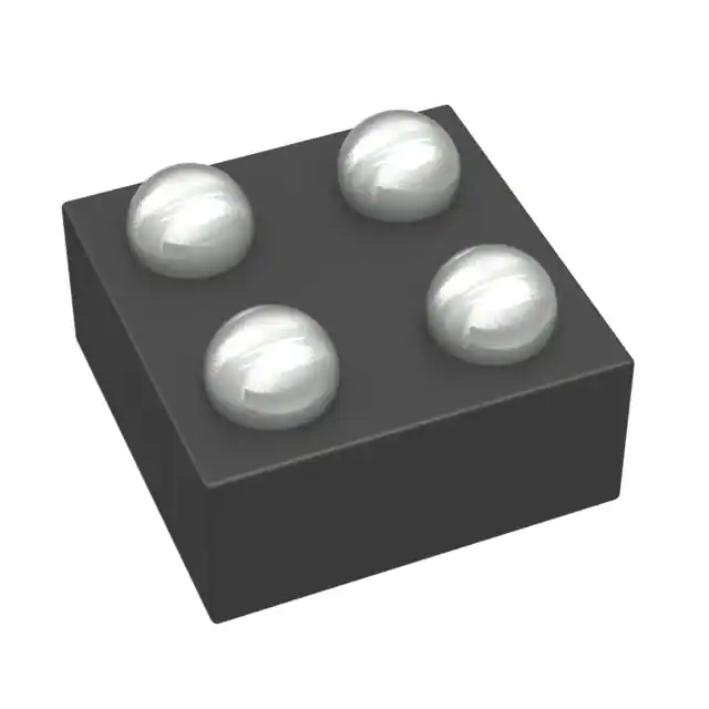
Texas Instruments TLV70515YFPR
- Part No.:
- TLV70515YFPR
- Manufacturer:
- Texas Instruments
- Package:
- 4-XFBGA, DSBGA
- Datasheet:
-
 TLV70515YFPR.pdf
- Description:
- IC REG LINEAR 1.5V 200MA 4DSBGA
- Quantity:
- Payment:

- Shipping:

Inventory:2,610
Please send an inquiry. Send us your inquiry, and we will respond immediately.
Product details
Overview
TLV70515YFPR from Texas Instruments is a 1.5-V fixed-output, 200-mA low-dropout (LDO) linear regulator in a 0.77-mm × 0.77-mm DSBGA package. It delivers 0.5% output accuracy, 35-μA quiescent current, and 145-mV dropout at 200 mA - optimized for Li-ion–powered handheld devices requiring stable, low-noise biasing of RF and digital circuitry.
For engineers reviewing the TLV70515YFPR datasheet, TLV70515YFPR pinout, TLV70515YFPR application, or TLV70515YFPR equivalent, key selection considerations include ultra-low profile packaging (0.15-mm max height), 0.1-μF minimum stable output capacitance, high PSRR (70 dB @ 1 kHz), thermal shutdown, and enable-controlled sequencing in space-constrained portable systems.
Technical Context
The TLV70515YFPR uses a PMOS pass transistor to achieve low dropout and maintain regulation down to (VIN – VOUT) = 145 mV at full load. Its error amplifier provides 0.5% DC accuracy over –40°C to +125°C and supports zero-load regulation.
It features an active-high enable pin with 0.9-V turn-on threshold and 0.4-V shutdown threshold, enabling direct interfacing with low-voltage GPIOs. Internal UVLO (1.9 V) and thermal shutdown (160°C) ensure robust operation under fault conditions.
Key Specifications
| Parameter | Value and Actual Design Meaning |
|---|---|
| Output Voltage | Fixed 1.5 V ±0.5% - ensures precise biasing for core logic and RF ICs without external feedback. |
| Max Output Current | 200 mA - sufficient for powering single-core microcontrollers, Bluetooth radios, or sensor signal chains. |
| Dropout Voltage | 145 mV @ 200 mA - enables operation from partially discharged Li-ion cells (down to ~1.65 V input). |
| Quiescent Current | 35 μA - minimizes battery drain in always-on or low-power sleep modes. |
| PSRR | 70 dB @ 1 kHz - suppresses switching noise from adjacent DC/DC converters feeding mixed-signal circuits. |
| Stable Capacitance | 0.1 μF ceramic - allows use of small, low-bias-drift capacitors, reducing PCB area and BOM cost. |
| Enable Threshold | VEN(HI) = 0.9 V, VEN(LO) = 0.4 V - compatible with 1.2-V and 1.8-V GPIOs without level-shifting. |
Pinout & Package
TLV70515YFPR is housed in a 4-pin, 0.77-mm × 0.77-mm DSBGA (YFP) package with 0.15-mm maximum height - ideal for ultra-thin mobile and wearable designs.
| Pin/Terminal | Circuit Role | Design Meaning |
|---|---|---|
| GND | Ground reference | Primary return path for load current and internal bias; must be connected to low-impedance system ground plane. |
| EN | Enable control input | Active-high logic input; drives regulator ON above 0.9 V, OFF below 0.4 V; draws only 0.01 μA leakage. |
| VIN | Input power supply | Accepts 2 V to 5.5 V; requires local 1-μF ceramic decoupling to GND for transient immunity. |
| VOUT | Regulated output | Delivers stable 1.5 V; requires ≥0.1-μF ceramic capacitor to GND for stability; no ESR restrictions. |
Key Features
| Feature | Design Value |
|---|---|
| Ultra-small footprint | 0.77 mm × 0.77 mm DSBGA - saves >60% board area vs. SOT-23, critical for compact wearables. |
| Low-noise regulation | 26.6 μVRMS (100 Hz–100 kHz) - prevents interference in sensitive RF receivers and ADC references. |
| Thermal & current protection | Integrated thermal shutdown (160°C) and current limit (260–550 mA) - prevents damage during shorts or overload. |
| Zero-load regulation | Maintains 1.5 V accuracy with 0 mA output - essential for standby power domains and wake-up circuitry. |
| UVLO circuit | 1.9 V turn-on threshold - blocks regulation until input rail is sufficiently established, avoiding brownout instability. |
Applications
| Wireless Handsets | Bluetooth® Devices |
|---|---|
Use Scenario: Powering baseband processor I/O banks and RF front-end bias rails in dual-SIM smartphones. IC Role / Device Role / Timing Role: Primary 1.5-V LDO supplying low-noise core voltage to transceiver ICs and memory interfaces. Use Value: 70-dB PSRR at 1 kHz rejects noise from PMIC switching stages, preserving receiver sensitivity and bit-error rate. |
Use Scenario: Supplying 1.5-V logic and radio sections in Bluetooth Low Energy (BLE) earbuds and trackers. IC Role / Device Role / Timing Role: Standby-mode LDO delivering regulated voltage to BLE SoC peripherals during advertising intervals. Use Value: 35-μA quiescent current extends battery life beyond 10 days on a 100-mAh cell, even with periodic wake-ups. |
| Zigbee® Networks | WLAN PC Add-On Cards |
Use Scenario: Biasing Zigbee mesh node microcontrollers and 2.4-GHz transceivers in smart home sensors. IC Role / Device Role / Timing Role: Fixed-output LDO providing clean 1.5-V supply to MCU cores and RF synthesizers. Use Value: 0.1-μF minimum output capacitance enables use of 0201-size ceramics, reducing solution size by 40% vs. legacy LDOs. |
Use Scenario: Regulating 1.5-V auxiliary rails for WLAN chipset I/O and clock buffers on mini-PCIe cards. IC Role / Device Role / Timing Role: Secondary LDO isolating noise-sensitive timing circuits from noisy host bus power. Use Value: 145-mV dropout allows uninterrupted operation as host 3.3-V rail sags during high-bandwidth data bursts. |
Equivalent & Alternatives
The following parts are listed as comparable options for similar LDO regulator applications.
| Alternative Part | Technical Difference | Application Difference | Selection Advice |
|---|---|---|---|
| TLS850F1EJXUMA1 | 500-mA rated, 3.3-V fixed output, automotive AEC-Q100 qualified; higher IQ (50 μA), larger HTSOP-8 package. | Targeted at automotive body electronics; not suitable for space-constrained consumer portables. | Select only if automotive qualification, higher current, or 3.3-V output is required - not a drop-in replacement. |
| AP7361D-15YG-13 | 300-mA rated, 1.5-V fixed output, SOT-23-5 package; 60-μA IQ, 250-mV dropout @ 300 mA, requires ≥1-μF COUT. | Higher dropout and larger footprint limit use in thin Li-ion devices; better suited for industrial modules with relaxed size constraints. | Consider when higher output current is needed and board area is less constrained - verify layout compatibility. |
Compared with TLS850F1EJXUMA1 and AP7361D-15YG-13, TLV70515YFPR offers the smallest footprint and lowest quiescent current among 1.5-V LDOs, making it uniquely suited for ultra-compact, battery-optimized designs where every micron and microamp matters.
Availability
TLV70515YFPR is available at Aetrix Electronics and suitable for wireless handsets, Bluetooth® devices, and Zigbee® networks requiring stable component supply across high-mix, low-volume production runs and rapid prototyping cycles.
Supply support for TLV70515YFPR includes scheduled delivery planning, volume procurement assistance, BOM continuity management, traceable sourcing, and lifecycle availability coordination for OEM customers, industrial embedded developers, connected-device designers, and electronics production programs.
Manufacturer
Texas Instruments is a global semiconductor leader focused on analog and embedded processing technologies, serving industrial, automotive, and personal electronics markets with high-reliability, application-optimized components.
The TLV705 series was designed specifically for battery-powered portable electronics - emphasizing ultra-low IQ, miniature packaging, and high PSRR to extend runtime and simplify power architecture in smartphones, wearables, and IoT edge nodes.
FAQ
What is the minimum input voltage required for TLV70515YFPR to regulate 1.5 V?
The TLV70515YFPR requires VIN ≥ VOUT + VDO. With a typical dropout of 145 mV at 200 mA, the minimum functional input is 1.645 V. However, the recommended operating range starts at 2 V per datasheet specifications to ensure guaranteed performance across temperature and process variation. Below 2 V, regulation may degrade or cease depending on load and junction temperature.
Can TLV70515YFPR operate without an output capacitor?
No - TLV70515YFPR requires a minimum effective output capacitance of 0.1 μF (ceramic) from VOUT to GND for stability. Omitting this capacitor causes oscillation and unregulated output. The device is optimized for low-ESR ceramics; tantalum or aluminum electrolytics are not recommended due to ESR and bias voltage derating effects.
Does TLV70515YFPR include reverse-voltage protection?
TLV70515YFPR does not include reverse-voltage protection. Its internal PMOS pass transistor has a body diode that conducts from VOUT to VIN if VOUT exceeds VIN. This uncontrolled conduction can damage upstream sources or cause system-level latch-up. TI recommends adding an external Schottky diode or dedicated reverse-protection IC if reverse voltage exposure is possible.
How does the enable pin (EN) behave during power-up?
The EN pin of TLV70515YFPR is active-high with a 0.9-V threshold. When VIN rises first, EN must reach 0.9 V before regulation begins - ensuring controlled sequencing. If EN is tied to VIN, the device powers up immediately after VIN crosses 0.9 V. For delayed startup, a resistor-divider or RC network can be used to delay EN assertion relative to VIN.
Is TLV70515YFPR compatible with 1.2-V GPIOs?
Yes - TLV70515YFPR's EN pin turns on at 0.9 V (min), making it directly compatible with 1.2-V GPIO outputs without level-shifting. At 1.2 V, EN is well above the 0.9-V threshold, ensuring reliable activation. Leakage into EN is only 0.01 μA, minimizing loading on weak GPIO drivers.
TLV70515YFPR Specifications
- Product attributes
- Attribute value
- Manufacturer:
- Texas Instruments
- Series:
- -
- Package/Case:
- 4-XFBGA, DSBGA
- Packaging:
- Tape & Reel (TR)
- Product Status:
- Active
- Output Configuration:
- Positive
- Output Type:
- Fixed
- Number of Regulators:
- 1
- Voltage - Input (Max):
- 5.5V
- Voltage - Output (Min/Fixed):
- 1.5V
- Voltage - Output (Max):
- -
- Voltage Dropout (Max):
- 0.25V @ 200mA
- Current - Output:
- 200mA
- Current - Quiescent (Iq):
- 55 µA
- Current - Supply (Max):
- 315 µA
- PSRR:
- 80dB ~ 55dB (10kHz ~ 1MHz)
- Control Features:
- Enable
- Protection Features:
- Over Current, Over Temperature, Reverse Polarity, Under Voltage Lockout (UVLO)
- Operating Temperature:
- -40°C ~ 125°C (TJ)
- Grade:
- -
- Qualification:
- -
- Mounting Type:
- Surface Mount
- Supplier Device Package:
- 4-DSBGA
TLV70515YFPR FAQ
1.How can I place an order for TLV70515YFPR through Aetrix?
Please submit a Request for Quotation (RFQ) for TLV70515YFPR on Aetrix. Our sales agent will provide a competitive quotation and guide you through the order confirmation once you accept the terms.
2.Are the price and stock information for TLV70515YFPR reliable?
The price and inventory of TLV70515YFPR are updated periodically and may fluctuate due to market conditions. Stock and pricing data are typically refreshed every 24 hours. Quotation validity for TLV70515YFPR is usually 5 days.
3.What payment methods are accepted for TLV70515YFPR?
We accept Wire Transfer, PayPal, Credit Card, Western Union, MoneyGram, and Escrow for TLV70515YFPR transactions.
Note: Certain payment methods may incur a processing fee.
4.How is shipping managed for TLV70515YFPR?
TLV70515YFPR orders can be shipped via leading logistics carriers, including DHL, UPS, FedEx, TNT, or Registered Mail.
Once your TLV70515YFPR order is processed, you will receive an email with the shipment details and tracking number.
Note: Tracking information may take up to 24 hours to appear. Express delivery typically takes 3–5 business days.
5.How can I obtain technical support or documentation for TLV70515YFPR?
For technical support, including TLV70515YFPR datasheets, pinout diagrams, or application guidance, please contact our engineering support team. They can provide detailed documentation and assistance for your TLV70515YFPR requirements.
6.How does Aetrix verify that TLV70515YFPR is sourced from the original manufacturer or authorized distributors?
All TLV70515YFPR products on Aetrix are procured from qualified distributors and authorized channels. Our dedicated quality assurance team conducts strict verification, including traceability checks and, if necessary, third-party testing. This ensures that TLV70515YFPR meets industry standards.
7.What is the process for return or replacement of TLV70515YFPR?
All TLV70515YFPR units undergo pre-shipment inspection (PSI). If there is an issue with TLV70515YFPR, returns or replacements are accepted under the following conditions:
1.Quantity discrepancies, incorrect items, or visible external defects (such as breakage or corrosion), acknowledged by Aetrix.
2.The issue is reported within 90 days of delivery.
3.The TLV70515YFPR part is unused and in its original packaging.
Return procedure for TLV70515YFPR:
1.Submit a request within 90 days.
2.Obtain a Return Material Authorization (RMA) from Aetrix.
TLV70515YFPR Tags

-
MIC5504-1.8YM5-TR
Microchip Technology
-
MIC5504-3.3YM5-TR
Microchip Technology

-
MIC5365-3.0YC5-TR
Microchip Technology
-
MIC5365-1.8YC5-TR
Microchip Technology
-
MIC5365-2.5YC5-TR
Microchip Technology
-
MIC5365-3.3YC5-TR
Microchip Technology

-
MIC5365-3.3YD5-TR
Microchip Technology

-
MIC5317-3.3YM5-TR
Microchip Technology

-
TLV1117LV33DCYR
Texas Instruments

-
MIC5317-3.3YMT-TZ
Microchip Technology

-
MIC5528-3.3YMT-TR
Microchip Technology

-
TLV75801PDRVR
Texas Instruments
Tech Hub
A D latch stores one bit while Enable controls when data can pass. This reference covers gate-level operation, truth tables, transparency, setup and hold timing, LE versus OE, common ICs and practical …

An SR latch stores one bit through cross-coupled feedback. This engineering reference covers NOR and NAND implementations, truth tables, forbidden-state recovery, gated operation, switch debouncing, fa…

Latch circuits retain one bit through feedback. This technical reference covers SR and D latches, truth tables, transparency, timing limits, latch-versus-flip-flop behavior, applications and common log…

An engineering guide to LED driver operation, constant-current and constant-voltage outputs, linear and switching topologies, dimming, IC selection, calculations, replacement compatibility, and fault c…

Operational amplifier guide covering op amp basics, feedback, ideal vs real op amps, common configurations, buffer circuits, offset, bias current, gain-bandwidth, slew rate, rail-to-rail limits and sel…

Jumper cables guide covering safe connection order, red and black clamp placement, final ground connection, cable gauge, length, clamp quality, copper vs CCA cables, jump starter comparison and battery…

LDO regulator guide covering low dropout voltage, power dissipation, thermal design, PSRR, output noise, capacitor stability, adjustable LDO circuits, LDO vs buck converter and datasheet selection chec…

Conditional Access Module guide covering CAM meaning, CI/CI+ interface, smart card authorization, DVB security workflow, TV and set-top box compatibility, internal electronics, ESD protection, connecto…

Guide to electronic component obsolescence covering EOL risk, PCN/PDN notices, last-time buy planning, replacement options, form-fit-function validation, counterfeit risk and BOM lifecycle management.

18650 battery guide covering lithium-ion cell basics, 3.6V/3.7V voltage, 4.2V charging, mAh and Wh capacity, protected cells, chargers, BMS, series-parallel packs, holders, welding and sourcing checks.…


