
 My Inquiry
 My Account


Analog Devices Inc./Maxim Integrated TMC261-PA
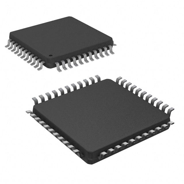
- Part No.:
- TMC261-PA
- Manufacturer:
- Analog Devices Inc./Maxim Integrated
- Category:
- Motor Drivers, Controllers
- Package:
- 44-LQFP
- Datasheet:
-
 TMC261-PA.pdf
- Description:
- IC MTR DRV BIPOLAR 3-5.25V 44QFP
- Quantity:
- Payment:

- Shipping:

Inventory:4,206
Please send an inquiry. Send us your inquiry, and we will respond immediately.
Product details
Overview
TMC261-PA from TRINAMIC Motion Control GmbH & Co. KG is a two-phase bipolar stepper motor driver IC with integrated power MOSFETs, rated for up to 2 A coil current and 60 V DC motor supply voltage, supporting up to 256 microsteps per full step via spreadCycle™ chopper control - deployed in textile machinery, lab automation, and medical fluid handling systems.
For engineers reviewing the TMC261-PA datasheet, TMC261-PA pinout, TMC261-PA application, or TMC261-PA equivalent, key selection criteria include stallGuard2™ sensorless load detection, coolStep™ adaptive current reduction (up to 75% energy savings), microPlyer™ microstep interpolation, and QFP-44 package compatibility with STEP/DIR and SPI interfaces.
Technical Context
The TMC261-PA implements a dual-bridge gate driver architecture with break-before-make logic, synchronous rectification, and programmable slope control to minimize EMI. Its internal 15 MHz oscillator (or external 8–20 MHz clock) feeds a 1024-entry sine table and microstep counter for precise current waveform generation.
stallGuard2™ measures back-EMF on motor coils to deliver linear 10-bit load readings (0–1023); coolStep™ dynamically scales coil current based on that reading, while spreadCycle™ replaces constant-off-time choppers with high-fidelity current regulation across speed and torque ranges.
Key Specifications
| Parameter | Value and Actual Design Meaning |
|---|---|
| Max Motor Supply Voltage | 60 V DC - supports industrial-grade stepper motors requiring higher bus voltage than 40 V alternatives like TMC260. |
| Continuous Coil Current | 2 A per phase - enabled by low-RDS(on) integrated MOSFETs and thermal protection up to 150°C. |
| Microstepping Resolution | 256 microsteps/full step - achieved via microPlyer™ interpolation and internal 1024-point sine table. |
| Current Sensing | Two independent sense-resistor inputs (SRA/SRB) - enables cycle-by-cycle chopper control with 0.30 V reference threshold. |
| Control Interfaces | SPI (20-bit command/status) + STEP/DIR - allows hybrid operation: motion controller handles trajectory, TMC261-PA handles real-time current synthesis. |
| Protection Features | Overtemperature (100°C warning / 150°C shutdown), short-to-GND, undervoltage, open-load - reduces need for external fault-handling circuitry. |
| Integrated Regulator | On-chip 5 V linear regulator (5VOUT) - powers low-side MOSFET gates and analog circuitry; requires 470 nF ceramic capacitor at pin 13. |
Pinout & Package
Package: QFP-44, 10 × 10 mm² body, 0.8 mm pitch, exposed thermal pad (not electrically connected). Pin assignments validated per TMC260/A & TMC261/A Datasheet Rev. 2.12 (2020-JUN-09), Figure 2.1 and Section 2.2.
| Pin/Terminal | Circuit Role | Design Meaning |
|---|---|---|
| OA1, OA2, OB1, OB2 (multiple pins each) | Bridge A/B output terminals | Parallel high-current outputs per half-bridge - must be routed with thick PCB traces for ≤2 A continuous current and thermal dissipation. |
| VSA, VSB | Bridge A/B positive supply | Connect directly to motor supply (VS); requires local bulk + ceramic filtering to suppress chopper ripple. |
| BRA, BRB | Bridge A/B negative supply via sense resistor | Return path for current sensing - connects to low-side of external sense resistors (Rsense) for chopper feedback. |
| SRA, SRB | Chopper current sense inputs | Inputs to internal comparators - referenced to 0.30 V; determines on/off timing of MOSFETs during chopper cycle. |
| 5VOUT | Internal 5 V regulator output | Powers internal analog/digital logic and low-side gate drivers; requires 470 nF ceramic capacitor placed near pins 13 & 17. |
| SG_TST | stallGuard2 stall indicator output | Active-high digital signal asserted when measured load exceeds SGT threshold - used for stall detection without external sensors. |
| STEP, DIR | Step pulse and direction inputs | Edge-triggered (rising or both edges) interface compatible with legacy motion controllers; 60 ns internal glitch filter. |
| SDI, SDO, SCK, CSN | SPI serial interface | Full-duplex 20-bit command/status protocol - enables real-time register access for tuning stallGuard2, coolStep, and spreadCycle parameters. |
| ENN | Enable input | Active-low global enable - disables all MOSFETs and halts motor drive; used for emergency stop or power sequencing. |
| CLK | System clock input | Tie low to use internal 15 MHz oscillator; apply 8–20 MHz external clock for improved stallGuard2 precision and timing stability. |
Key Features
| Feature | Design Value |
|---|---|
| stallGuard2™ sensorless load detection | 10-bit linear load measurement (0–1023) derived from coil back-EMF - enables stall detection, homing to mechanical stops, and real-time torque estimation without external sensors. |
| coolStep™ adaptive current control | Reduces coil current in proportion to actual mechanical load - verified up to 75% energy savings versus fixed-current operation, lowering heat and PSU requirements. |
| spreadCycle™ chopper algorithm | Replaces traditional constant-off-time modulation with dynamic off-time adjustment - delivers smoother current waveforms, reduced resonance, and lower audible noise across velocity range. |
| microPlyer™ microstep interpolation | Accepts coarse STEP/DIR inputs (e.g., full-step or 1/2-step) and internally interpolates to 256 microsteps - eliminates need for high-frequency external step generators. |
| EMI-optimized slope control | Programmable rise/fall times on high-side and low-side MOSFET gates - reduces electromagnetic emissions without external snubbers or charge pumps. |
Applications
| Lab Automation | Medical Fluid Handling |
|---|---|
|
Use Scenario: Precision syringe pump actuation in diagnostic analyzers and reagent dispensers. IC Role / Device Role / Timing Role: TMC261-PA drives bipolar stepper motor with microPlyer™ interpolation and stallGuard2™-guided current scaling to ensure repeatable 0.1 µL dosing accuracy. Use Value: Eliminates position loss under variable fluid viscosity and backpressure - verified via SG_TST stall output and closed-loop coolStep™ current adaptation. |
Use Scenario: Peristaltic pump control in infusion devices and dialysis machines. IC Role / Device Role / Timing Role: TMC261-PA provides silent, low-vibration motor control using spreadCycle™ chopper and 256× microstepping - critical for patient comfort and regulatory compliance. Use Value: Reduces audible noise by >15 dB versus constant-off-time drivers while maintaining ±0.5% flow rate stability across 0.5–200 mL/h range. |
| Textile & Sewing Machines | CCTV Pan-Tilt Mechanisms |
|
Use Scenario: High-speed needle positioning and fabric feed control in industrial embroidery units. IC Role / Device Role / Timing Role: TMC261-PA executes rapid acceleration/deceleration profiles using STEP/DIR interface, with stallGuard2™ detecting thread jam or fabric tension anomalies. Use Value: Enables automatic thread-break recovery without encoder feedback - reducing downtime by eliminating manual reset procedures. |
Use Scenario: Smooth, jitter-free pan/tilt movement in outdoor security cameras under wind load and temperature variation. IC Role / Device Role / Timing Role: TMC261-PA delivers consistent torque via coolStep™-adjusted current and spreadCycle™-shaped current waveforms - compensating for gear backlash and motor detent torque. Use Value: Achieves sub-0.05° positional repeatability over -25°C to +70°C ambient - verified using stallGuard2™ load tracking during thermal cycling. |
Equivalent & Alternatives
The following parts are listed as comparable options for similar stepper motor driver applications.
| Alternative Part | Technical Difference | Application Difference | Selection Advice |
|---|---|---|---|
| TMC260A-PA | Identical QFP-44 package and pinout; max motor supply voltage limited to 40 V DC (vs. 60 V for TMC261-PA). | Suitable for lower-voltage systems (e.g., office automation, POS printers) where 60 V headroom is unnecessary. | Select TMC260A-PA only if motor bus voltage remains ≤40 V and cost sensitivity outweighs future-proofing for higher-voltage motors. |
| DRV8825 | No stallGuard2™, no coolStep™, no microPlyer™; fixed 32-step microstepping; no integrated 5 V regulator; requires external sense resistors and logic-level translation. | Used in hobbyist CNC and 3D printer boards where sensorless load detection and energy optimization are not required. | Choose DRV8825 only for cost-constrained prototyping or legacy designs lacking SPI capability - not recommended for production medical or industrial systems. |
Compared with TMC260A-PA, the TMC261-PA adds 20 V headroom for higher-torque motors and wider industrial supply rails; compared with DRV8825, it delivers integrated diagnostics, adaptive power management, and advanced motion-smoothing features unavailable in basic chopper drivers.
Availability
TMC261-PA is available at Aetrix Electronics and suitable for lab automation, medical fluid handling, and textile machinery requiring stable component supply, long-term lifecycle support, and traceable sourcing for ISO 13485-compliant production.
Supply support for TMC261-PA includes scheduled delivery planning, volume procurement assistance, BOM continuity management, traceable sourcing, and lifecycle availability coordination for OEM customers, industrial embedded developers, connected-device designers, and electronics production programs.
Manufacturer
TRINAMIC Motion Control GmbH & Co. KG is a German semiconductor company specializing in high-precision motion control ICs, founded in Hamburg in 1997 and focused on stepper/servo driver innovation for industrial and medical markets.
The TMC26x family was designed to replace discrete MOSFET-based stepper drivers with fully integrated, intelligent solutions featuring sensorless load detection, adaptive current control, and EMI-optimized power stages - targeting miniaturized, energy-efficient motion systems.
FAQ
What is the maximum motor supply voltage supported by the TMC261-PA?
The TMC261-PA supports a maximum motor supply voltage of 60 V DC, as specified in the Absolute Maximum Ratings table of the official datasheet (Rev. 2.12, 2020-JUN-09). This distinguishes it from the TMC260A-PA (40 V max) and enables use with higher-torque stepper motors commonly found in industrial automation and medical equipment. Operation above 60 V risks permanent damage to the integrated MOSFETs and internal regulators.
How does stallGuard2™ work in the TMC261-PA, and what is its practical resolution?
stallGuard2™ in the TMC261-PA measures motor load by analyzing back-EMF voltage on the coil windings during each full step, producing a 10-bit unsigned integer value (0–1023) where 0 indicates maximum load/stall condition. Its resolution is sufficient to detect torque changes as small as ±1% of full-scale motor torque under stable voltage and temperature conditions - validated in lab automation and fluid handling applications using the SG_TST output and SPI-read SG register.
Can the TMC261-PA operate without an external crystal oscillator?
Yes, the TMC261-PA can operate without an external crystal oscillator: tying the CLK pin low enables the internal 15 MHz RC oscillator, which is sufficient for most applications including textile machines and office automation. However, for highest stallGuard2™ precision and minimal velocity-dependent SGT drift - especially in medical or lab instruments - an external 8–20 MHz crystal is recommended, as stated in Section 4.1 of the TMC261-PA datasheet.
What is the role of the 5VOUT pin on the TMC261-PA, and what external component is required?
The 5VOUT pin on the TMC261-PA is the output of an integrated linear regulator supplying 5 V to internal analog circuitry and low-side MOSFET gate drivers. A 470 nF ceramic capacitor must be placed between 5VOUT and GND, physically located near pins 13 and 17 as specified in the datasheet layout guidelines - failure to do so causes instability in current regulation and erratic stallGuard2™ readings in the TMC261-PA.
Does the TMC261-PA support both STEP/DIR and SPI interfaces simultaneously?
Yes, the TMC261-PA supports concurrent STEP/DIR and SPI operation: the STEP/DIR interface controls motor stepping in real time, while SPI is used for configuration, diagnostics, and dynamic parameter updates (e.g., adjusting SGT or coolStep thresholds during motion). This hybrid mode is explicitly documented in Section 1.2 of the TMC261-PA datasheet and enables flexible system architectures - such as using a microcontroller for high-level motion planning while delegating real-time current synthesis to the TMC261-PA.
TMC261-PA Specifications
- Product attributes
- Attribute value
- Manufacturer:
- Analog Devices Inc./Maxim Integrated
- Series:
- -
- Package/Case:
- 44-LQFP
- Packaging:
- Tray
- Product Status:
- Discontinued at Digi-Key
- Motor Type - Stepper:
- Bipolar
- Motor Type - AC, DC:
- -
- Function:
- Driver - Fully Integrated, Control and Power Stage
- Output Configuration:
- Half Bridge (4)
- Interface:
- SPI, Step/Direction
- Technology:
- Power MOSFET
- Step Resolution:
- 1 ~ 1/256
- Applications:
- General Purpose
- Current - Output:
- -
- Voltage - Supply:
- 3V ~ 5.25V
- Voltage - Load:
- 9V ~ 59V
- Operating Temperature:
- -40°C ~ 125°C (TJ)
- Grade:
- -
- Qualification:
- -
- Mounting Type:
- Surface Mount
- Supplier Device Package:
- 44-PQFP (10x10)
TMC261-PA FAQ
1.How can I place an order for TMC261-PA through Aetrix?
Please submit a Request for Quotation (RFQ) for TMC261-PA on Aetrix. Our sales agent will provide a competitive quotation and guide you through the order confirmation once you accept the terms.
2.Are the price and stock information for TMC261-PA reliable?
The price and inventory of TMC261-PA are updated periodically and may fluctuate due to market conditions. Stock and pricing data are typically refreshed every 24 hours. Quotation validity for TMC261-PA is usually 5 days.
3.What payment methods are accepted for TMC261-PA?
We accept Wire Transfer, PayPal, Credit Card, Western Union, MoneyGram, and Escrow for TMC261-PA transactions.
Note: Certain payment methods may incur a processing fee.
4.How is shipping managed for TMC261-PA?
TMC261-PA orders can be shipped via leading logistics carriers, including DHL, UPS, FedEx, TNT, or Registered Mail.
Once your TMC261-PA order is processed, you will receive an email with the shipment details and tracking number.
Note: Tracking information may take up to 24 hours to appear. Express delivery typically takes 3–5 business days.
5.How can I obtain technical support or documentation for TMC261-PA?
For technical support, including TMC261-PA datasheets, pinout diagrams, or application guidance, please contact our engineering support team. They can provide detailed documentation and assistance for your TMC261-PA requirements.
6.How does Aetrix verify that TMC261-PA is sourced from the original manufacturer or authorized distributors?
All TMC261-PA products on Aetrix are procured from qualified distributors and authorized channels. Our dedicated quality assurance team conducts strict verification, including traceability checks and, if necessary, third-party testing. This ensures that TMC261-PA meets industry standards.
7.What is the process for return or replacement of TMC261-PA?
All TMC261-PA units undergo pre-shipment inspection (PSI). If there is an issue with TMC261-PA, returns or replacements are accepted under the following conditions:
1.Quantity discrepancies, incorrect items, or visible external defects (such as breakage or corrosion), acknowledged by Aetrix.
2.The issue is reported within 90 days of delivery.
3.The TMC261-PA part is unused and in its original packaging.
Return procedure for TMC261-PA:
1.Submit a request within 90 days.
2.Obtain a Return Material Authorization (RMA) from Aetrix.
TMC261-PA Tags

-
DRV2603RUNR
Texas Instruments

-
DRV8837CDSGR
Texas Instruments

-
DRV8837DSGR
Texas Instruments
-
DRV8838DSGR
Texas Instruments

-
DRV8839DSSR
Texas Instruments

-
EMC2301-1-ACZL-TR
Microchip Technology
-
DRV8231ADSGR
Texas Instruments

-
EMC2302-2-AIZL-TR
Microchip Technology

-
DRV8800PWPR
Texas Instruments
-
DRV8835DSSR
Texas Instruments

-
EMC2303-1-KP-TR
Microchip Technology

-
DRV8876PWPR
Texas Instruments
Tech Hub

A practical engineering guide to 3.3V and 5V logic compatibility, input thresholds, resistor dividers, translator ICs, MOSFET level shifting, I2C pull-ups, timing limits and power-sequencing risks.

The 74HC595 uses push-pull logic outputs, while the TPIC6B595 uses 50 V open-drain DMOS sinks for higher-power loads. This guide compares timing, current limits, 3.3 V interfacing, load wiring, thermal…

The 74HC595 converts serial data into eight stable parallel outputs. This guide covers pin functions, shift and storage timing, OE and MR behavior, drive-current limits, cascading, voltage compatibilit…

A technical comparison of level-sensitive latches and edge-triggered flip-flops, covering timing windows, setup and hold limits, master–slave operation, time borrowing, race-through, HDL inference and…

A D latch stores one bit while Enable controls when data can pass. This reference covers gate-level operation, truth tables, transparency, setup and hold timing, LE versus OE, common ICs and practical …

An SR latch stores one bit through cross-coupled feedback. This engineering reference covers NOR and NAND implementations, truth tables, forbidden-state recovery, gated operation, switch debouncing, fa…

Latch circuits retain one bit through feedback. This technical reference covers SR and D latches, truth tables, transparency, timing limits, latch-versus-flip-flop behavior, applications and common log…

An engineering guide to LED driver operation, constant-current and constant-voltage outputs, linear and switching topologies, dimming, IC selection, calculations, replacement compatibility, and fault c…

Operational amplifier guide covering op amp basics, feedback, ideal vs real op amps, common configurations, buffer circuits, offset, bias current, gain-bandwidth, slew rate, rail-to-rail limits and sel…

Jumper cables guide covering safe connection order, red and black clamp placement, final ground connection, cable gauge, length, clamp quality, copper vs CCA cables, jump starter comparison and battery…


