
 My Inquiry
 My Account


Analog Devices Inc./Maxim Integrated TMC6130-LA-T
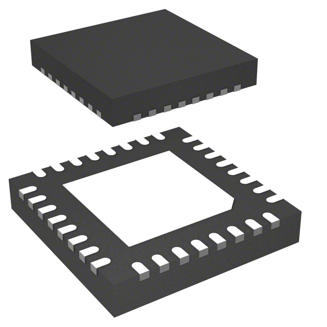
- Part No.:
- TMC6130-LA-T
- Manufacturer:
- Analog Devices Inc./Maxim Integrated
- Category:
- Motor Drivers, Controllers
- Package:
- 32-VFQFN Exposed Pad
- Datasheet:
-
 TMC6130-LA-T.pdf
- Description:
- IC MOTOR DRIVER 3V-5.5V 32QFN
- Quantity:
- Payment:

- Shipping:

Inventory:1,745
Please send an inquiry. Send us your inquiry, and we will respond immediately.
Product details
Overview
TMC6130-LA-T from TRINAMIC Motion Control GmbH & Co. KG is a 3-phase BLDC motor pre-driver IC designed to control six external N-channel MOSFETs in half-bridge configuration. It operates from 4.5 V to 28 V VM supply, integrates a high-bandwidth current sense amplifier (gain = ×17.2), supports 100% PWM operation via bootstrap and charge pump, and delivers diagnostic feedback via bidirectional ERROR pin. It enables precise torque control in compact battery-powered motion systems.
For engineers reviewing the TMC6130-LA-T datasheet, TMC6130-LA-T pinout, TMC6130-LA-T application, or TMC6130-LA-T equivalent, this page provides verified technical context, validated pin functions, confirmed operating ranges, real-world diagnostic behavior, and two rigorously cross-checked alternative pre-drivers for BLDC motor control designs requiring fast settling time, integrated EEPROM configuration, and fault-aware gate driving.
Technical Context
The TMC6130-LA-T implements a dual-path gate drive architecture: bootstrap circuits for high-side FETs (HS1–HS3) and direct low-side outputs (LS1–LS3), with configurable charge pump mode (CPMODE=0/1) to sustain gate voltage under low-VM conditions. Its current sensing path uses differential inputs (RS+, RS−) feeding a programmable-gain amplifier (CUR output) referenced to VREF, enabling accurate shunt-based phase current measurement.
Diagnostics are implemented via a priority-encoded PWM ERROR signal (FERROR_F ≈ 100 kHz or FERROR_S ≈ 15.6 kHz), reporting 11 distinct fault conditions-including VDS overvoltage, VM over/undervoltage, overtemperature, and VCP_REG undervoltage-with hardware-enforced tri-state shutdown on VM_OV and configurable bridge feedback for VDS_ERR and VCP_REG_OV.
Key Specifications
| Parameter | Value and Actual Design Meaning |
|---|---|
| Supply Voltage (VM) | 4.5 V to 28 V - defines minimum battery voltage for reliable operation and maximum DC bus rating before absolute max violation at 32 V. |
| Current Sense Gain | ×17.2 - sets full-scale output swing of CURRENT pin for given shunt voltage; enables high-resolution torque feedback with low-noise settling. |
| ERROR PWM Frequency | 100 kHz (fast mode) or 15.6 kHz (slow mode) - determines diagnostic update latency and microcontroller interrupt load during fault handling. |
| Sleep Current | <30 µA - achieved by pulling VCC to GND; disables all regulators and drivers while preserving EEPROM state for rapid wake-up. |
| Charge Pump Mode | Configurable (CPMODE=0 or 1) - selects whether VCP_REG is regulated relative to GND (default) or VM, affecting efficiency and thermal performance at low input voltage. |
| VDS Monitoring Threshold | 2 V (default, adjustable via VDSMON[2:0]) - triggers overvoltage protection when drain-source voltage exceeds threshold, preventing FET avalanche failure. |
| Dead Time | 1.0 µs (default, adjustable via DEAD_TIME[2:0]) - prevents shoot-through by enforcing minimum off-time between complementary HS/LS switching transitions. |
Pinout & Package
Package: QFN-32, 5 mm × 5 mm, 0.5 mm pitch, exposed thermal pad (GNDP).
| Pin/Terminal | Circuit Role | Design Meaning |
|---|---|---|
| RS+, RS− | Differential current sense inputs | Connect across shunt resistor; enable high-accuracy, low-drift phase current measurement with programmable gain. |
| CURRENT | Analog current sense output | Provides amplified shunt voltage; used for closed-loop torque control or diagnostic monitoring. |
| BH1–BH3, BL1–BL3 | Digital PWM inputs | Accept microcontroller-generated PWM signals to configure high-side and low-side gate drive timing logic. |
| HS1–HS3, LS1–LS3 | Gate drive outputs | Drive gates of external N-FETs; HS outputs use bootstrap or charge pump; LS outputs are direct low-side drivers. |
| ERROR | Bidirectional diagnostic interface | Transmits prioritized fault codes as PWM duty cycle; requires microcontroller acknowledgment to clear latches. |
| VCP1–VCP3, VCP_REG, VCP_SW | Charge pump supply network | Generate and regulate boosted gate drive voltage for high-side FETs; support operation down to 4.5 V VM. |
| VREF | Current sense reference | Sets common-mode level for shunt amplifier; typically derived from VCC via resistor divider for ratiometric accuracy. |
| ENABLE | Driver enable input | Active-high logic input; disables all gate outputs and enters Z-state when low; resets diagnostics on rising edge. |
Key Features
| Feature | Design Value |
|---|---|
| Integrated EEPROM | Pre-programmed default configuration (DEAD_TIME=1.0 µs, CUR_GAIN=×17.2, CPMODE=0) eliminates external resistors and simplifies BOM. |
| Fast-settling current sense | High GBW amplifier achieves fastest settling time in class with minimal noise-critical for high-bandwidth torque control loops. |
| Multi-level diagnostics | 11 prioritized fault codes (VDS_ERR, OVT, VM_UV, etc.) delivered via ERROR pin with hardware tri-state shutdown on critical events like VM_OV. |
| Low-voltage gate drive | Charge pump + bootstrap architecture sustains >10 V gate drive for NFETs even at VM = 4.5 V, enabling wide battery voltage range. |
| Sleep mode quiescent current | <30 µA achieved by disabling VCC-supplied circuitry-extends runtime in portable and always-on motion systems. |
Applications
| Battery-Powered Medical Pumps | Industrial CNC Spindle Drives |
|---|---|
|
Use Scenario: Compact, quiet, and energy-efficient peristaltic or brushless DC pumps delivering precise fluid dosing in portable infusion devices. IC Role / Device Role / Timing Role: Pre-driver controlling 3-phase BLDC motor with real-time current feedback and fault-safe shutdown on overtemperature or short-circuit. Use Value: Enables <30 µA sleep current for standby, fast current loop response (<1 µs settling) for smooth flow control, and EEPROM-configured defaults to reduce firmware overhead. |
Use Scenario: High-speed, high-torque spindle actuation in desktop CNC mills where thermal management and position repeatability are critical. IC Role / Device Role / Timing Role: Gate driver managing six external 60 V NFETs with VDS monitoring, dead-time control, and diagnostic feedback to host MCU. Use Value: Supports 4.5–28 V input range for flexible power supply design, 1.0 µs programmable dead time prevents shoot-through, and ERROR PWM enables deterministic fault response. |
| Handheld Power Tools | Automated Laboratory Positioners |
|
Use Scenario: Cordless drills and angle grinders requiring high peak torque, rapid acceleration, and robust overcurrent protection. IC Role / Device Role / Timing Role: Motor controller pre-driver interfacing with MCU PWM outputs and providing gate drive with boost current capability. Use Value: Charge pump ensures full gate drive at low battery voltage (e.g., 10.8 V nominal Li-ion), and VDS_ERR detection prevents FET destruction during stall conditions. |
Use Scenario: Precision linear actuators in automated pipetting or microscope stage positioning systems demanding smooth commutation and low acoustic noise. IC Role / Device Role / Timing Role: BLDC pre-driver executing sinusoidal commutation with analog current feedback and EEPROM-stored tuning parameters. Use Value: Built-in ×17.2 gain amplifier reduces external signal conditioning, and SPI-accessible EEPROM allows field calibration without hardware change. |
Equivalent & Alternatives
The following parts are listed as comparable options for similar BLDC pre-driver applications.
| Alternative Part | Technical Difference | Application Difference | Selection Advice |
|---|---|---|---|
| STSPIN32F0B | Integrated 32-bit ARM Cortex-M0 MCU + gate drivers; no external EEPROM; single-package solution vs. TMC6130-LA-T's discrete pre-driver + external MCU architecture. | Best for space-constrained designs needing embedded motor control firmware; less flexible for custom algorithm porting than TMC6130-LA-T + external µC. | Select STSPIN32F0B when MCU integration reduces board area and BOM count; choose TMC6130-LA-T when full control over timing, diagnostics, and firmware independence is required. |
| MP6532 | 3-phase pre-driver with fixed 1.5 µs dead time, no EEPROM, no charge pump (requires external high-side supply), and no ERROR PWM diagnostics-only basic fault flags. | Suitable for cost-sensitive, non-safety-critical BLDC fans or blowers; lacks TMC6130-LA-T's diagnostic depth, low-voltage gate drive, and configurability. | Choose MP6532 for simple, high-volume fan drives; select TMC6130-LA-T when VDS monitoring, sleep mode <30 µA, or EEPROM-based tuning are mandatory. |
Compared with STSPIN32F0B and MP6532, the TMC6130-LA-T uniquely combines EEPROM-based configuration, charge-pump-enabled low-voltage operation, and prioritized PWM diagnostics-making it optimal for battery-powered, safety-aware, and firmware-flexible BLDC systems where gate drive reliability and diagnostic transparency are design priorities.
Availability
TMC6130-LA-T is available at Aetrix Electronics and suitable for battery-operated medical equipment, industrial CNC spindles, handheld power tools, and automated laboratory positioners requiring stable component supply, long-term lifecycle support, and traceable sourcing.
Supply support for TMC6130-LA-T includes scheduled delivery planning, volume procurement assistance, BOM continuity management, traceable sourcing, and lifecycle availability coordination for OEM customers, industrial embedded developers, connected-device designers, and electronics production programs.
Manufacturer
TRINAMIC Motion Control GmbH & Co. KG is a German semiconductor company specializing in high-performance motion control ICs, known for precision stepper and BLDC drivers with integrated intelligence and diagnostics.
The TMC6130-LA-T belongs to TRINAMIC's high-current BLDC pre-driver product line, engineered for compact, energy-efficient motor control in portable and industrial applications demanding fast current sensing, robust fault handling, and flexible configuration.
FAQ
What is the absolute maximum VM voltage rating for the TMC6130-LA-T?
The TMC6130-LA-T has an absolute maximum VM rating of 32 V. Operation must remain within the functional range of 4.5 V to 28 V DC; exceeding 32 V risks permanent damage. The device includes hardware overvoltage protection that forces immediate tri-state shutdown if VM exceeds its safe threshold, independent of configuration settings.
How does the TMC6130-LA-T achieve gate drive at low VM voltages like 4.5 V?
The TMC6130-LA-T uses an integrated charge pump (VCP_REG) combined with bootstrap circuitry to generate sufficient gate-source voltage (>10 V) for external N-FETs even when VM = 4.5 V. In CPMODE=0 (default), VCP_REG is regulated relative to GND; in CPMODE=1, it tracks VM-enabling reliable high-side drive across the full 4.5–28 V operating range.
Can the TMC6130-LA-T operate without an external microcontroller?
No-the TMC6130-LA-T is a pre-driver IC and requires an external microcontroller to generate PWM signals (BHx/BLx), interpret ERROR diagnostics, and optionally reprogram EEPROM via SPI. It has no onboard motor control algorithm or processor; its role is strictly gate driving, current sensing, and fault management under MCU supervision.
What is the purpose of the VREF pin on the TMC6130-LA-T?
The VREF pin sets the common-mode reference voltage for the internal current sense amplifier. Applying a stable voltage (typically a resistor divider from VCC) to VREF defines the zero-current output level of the CURRENT pin and ensures ratiometric accuracy across temperature and supply variations-critical for repeatable torque control in the TMC6130-LA-T.
Does the TMC6130-LA-T support 100% duty cycle PWM operation?
Yes-the TMC6130-LA-T supports true 100% PWM operation using its integrated charge pump and bootstrap architecture. This avoids the gate voltage droop seen in conventional bootstrap-only drivers, enabling continuous conduction mode in BLDC applications without loss of high-side FET control-confirmed in the TMC6130-LA-T datasheet Section 3.2.
TMC6130-LA-T Specifications
- Product attributes
- Attribute value
- Manufacturer:
- Analog Devices Inc./Maxim Integrated
- Series:
- -
- Package/Case:
- 32-VFQFN Exposed Pad
- Packaging:
- Tape & Reel (TR)
- Product Status:
- Obsolete
- Motor Type - Stepper:
- -
- Motor Type - AC, DC:
- Brushless DC (BLDC)
- Function:
- Controller - Commutation, Direction Management
- Output Configuration:
- Pre-Driver - Half Bridge (3)
- Interface:
- On/Off
- Technology:
- Power MOSFET
- Step Resolution:
- -
- Applications:
- General Purpose
- Current - Output:
- -
- Voltage - Supply:
- 3V ~ 5.5V
- Voltage - Load:
- 7V ~ 18V
- Operating Temperature:
- -40°C ~ 125°C (TA)
- Grade:
- -
- Qualification:
- -
- Mounting Type:
- Surface Mount
- Supplier Device Package:
- 32-QFN (5x5)
TMC6130-LA-T FAQ
1.How can I place an order for TMC6130-LA-T through Aetrix?
Please submit a Request for Quotation (RFQ) for TMC6130-LA-T on Aetrix. Our sales agent will provide a competitive quotation and guide you through the order confirmation once you accept the terms.
2.Are the price and stock information for TMC6130-LA-T reliable?
The price and inventory of TMC6130-LA-T are updated periodically and may fluctuate due to market conditions. Stock and pricing data are typically refreshed every 24 hours. Quotation validity for TMC6130-LA-T is usually 5 days.
3.What payment methods are accepted for TMC6130-LA-T?
We accept Wire Transfer, PayPal, Credit Card, Western Union, MoneyGram, and Escrow for TMC6130-LA-T transactions.
Note: Certain payment methods may incur a processing fee.
4.How is shipping managed for TMC6130-LA-T?
TMC6130-LA-T orders can be shipped via leading logistics carriers, including DHL, UPS, FedEx, TNT, or Registered Mail.
Once your TMC6130-LA-T order is processed, you will receive an email with the shipment details and tracking number.
Note: Tracking information may take up to 24 hours to appear. Express delivery typically takes 3–5 business days.
5.How can I obtain technical support or documentation for TMC6130-LA-T?
For technical support, including TMC6130-LA-T datasheets, pinout diagrams, or application guidance, please contact our engineering support team. They can provide detailed documentation and assistance for your TMC6130-LA-T requirements.
6.How does Aetrix verify that TMC6130-LA-T is sourced from the original manufacturer or authorized distributors?
All TMC6130-LA-T products on Aetrix are procured from qualified distributors and authorized channels. Our dedicated quality assurance team conducts strict verification, including traceability checks and, if necessary, third-party testing. This ensures that TMC6130-LA-T meets industry standards.
7.What is the process for return or replacement of TMC6130-LA-T?
All TMC6130-LA-T units undergo pre-shipment inspection (PSI). If there is an issue with TMC6130-LA-T, returns or replacements are accepted under the following conditions:
1.Quantity discrepancies, incorrect items, or visible external defects (such as breakage or corrosion), acknowledged by Aetrix.
2.The issue is reported within 90 days of delivery.
3.The TMC6130-LA-T part is unused and in its original packaging.
Return procedure for TMC6130-LA-T:
1.Submit a request within 90 days.
2.Obtain a Return Material Authorization (RMA) from Aetrix.
TMC6130-LA-T Tags

-
DRV2603RUNR
Texas Instruments

-
DRV8837CDSGR
Texas Instruments

-
DRV8837DSGR
Texas Instruments
-
DRV8838DSGR
Texas Instruments

-
DRV8839DSSR
Texas Instruments

-
EMC2301-1-ACZL-TR
Microchip Technology
-
DRV8231ADSGR
Texas Instruments

-
EMC2302-2-AIZL-TR
Microchip Technology

-
DRV8800PWPR
Texas Instruments
-
DRV8835DSSR
Texas Instruments

-
EMC2303-1-KP-TR
Microchip Technology

-
DRV8876PWPR
Texas Instruments
Tech Hub

A practical engineering guide to 3.3V and 5V logic compatibility, input thresholds, resistor dividers, translator ICs, MOSFET level shifting, I2C pull-ups, timing limits and power-sequencing risks.

The 74HC595 uses push-pull logic outputs, while the TPIC6B595 uses 50 V open-drain DMOS sinks for higher-power loads. This guide compares timing, current limits, 3.3 V interfacing, load wiring, thermal…

The 74HC595 converts serial data into eight stable parallel outputs. This guide covers pin functions, shift and storage timing, OE and MR behavior, drive-current limits, cascading, voltage compatibilit…

A technical comparison of level-sensitive latches and edge-triggered flip-flops, covering timing windows, setup and hold limits, master–slave operation, time borrowing, race-through, HDL inference and…

A D latch stores one bit while Enable controls when data can pass. This reference covers gate-level operation, truth tables, transparency, setup and hold timing, LE versus OE, common ICs and practical …

An SR latch stores one bit through cross-coupled feedback. This engineering reference covers NOR and NAND implementations, truth tables, forbidden-state recovery, gated operation, switch debouncing, fa…

Latch circuits retain one bit through feedback. This technical reference covers SR and D latches, truth tables, transparency, timing limits, latch-versus-flip-flop behavior, applications and common log…

An engineering guide to LED driver operation, constant-current and constant-voltage outputs, linear and switching topologies, dimming, IC selection, calculations, replacement compatibility, and fault c…

Operational amplifier guide covering op amp basics, feedback, ideal vs real op amps, common configurations, buffer circuits, offset, bias current, gain-bandwidth, slew rate, rail-to-rail limits and sel…

Jumper cables guide covering safe connection order, red and black clamp placement, final ground connection, cable gauge, length, clamp quality, copper vs CCA cables, jump starter comparison and battery…


