
 My Inquiry
 My Account


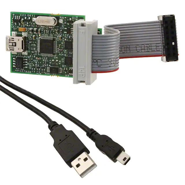
Texas Instruments TMDSEMU100U-14T
- Part No.:
- TMDSEMU100U-14T
- Manufacturer:
- Texas Instruments
- Category:
- Programmers, Emulators, and Debuggers
- Package:
- Datasheet:
-
 TMDSEMU100U-14T.pdf
- Description:
- XDS100 USB JTAG EMULATOR
- Quantity:
- Payment:

- Shipping:

Inventory:4,077
Please send an inquiry. Send us your inquiry, and we will respond immediately.
Product details
Overview
TMDSEMU100U-14T from Texas Instruments is a USB-based JTAG emulator for debugging and programming TI microcontrollers and processors, supporting IEEE 1149.1 (JTAG) and SWD interfaces, with up to 100 MHz TCK frequency, 14-pin ARM Cortex debug connector, and real-time trace capability for C2000 and MSP432 devices.
For engineers reviewing the TMDSEMU100U-14T datasheet, TMDSEMU100U-14T pinout, TMDSEMU100U-14T application, or TMDSEMU100U-14T equivalent, this device serves as a production-grade debug probe for TI MCU/MPU development, requiring precise JTAG/SWD signal integrity, host PC USB 2.0 connectivity, and CCS v10+ or IAR EWARM toolchain integration.
Technical Context
The TMDSEMU100U-14T implements a high-speed USB 2.0 interface to bridge host PC debug commands to target device JTAG/SWD pins, featuring on-board level-shifting for 1.2 V–5 V target voltage support, integrated isolation for noise immunity, and firmware-upgradable architecture via TI's Code Composer Studio.
It supports boundary-scan testing, flash programming, real-time variable monitoring, and instruction-level single-stepping across TI's C2000 Real-Time MCUs, MSP432 Arm-based MCUs, and selected Sitara AMx processors - all using the standardized 14-pin ARM Cortex Debug Connector (ARM 2×7 layout).
Key Specifications
| Parameter | Value and Actual Design Meaning |
|---|---|
| Interface | USB 2.0 High-Speed (480 Mbps) host connection; no external driver required on Windows/macOS/Linux |
| Debug Protocols | IEEE 1149.1 JTAG and ARM Serial Wire Debug (SWD); supports both legacy and modern TI devices |
| Max TCK Frequency | 100 MHz - enables fast flash programming and real-time trace capture on high-performance targets |
| Target Voltage Range | 1.2 V to 5.0 V - auto-sensing and level-shifted I/O eliminates need for external voltage translators |
| Connector | 14-pin ARM Cortex Debug (2×7) - industry-standard pinout compatible with TI LaunchPads and custom boards |
| Trace Support | Real-time instruction and data trace via SWO (Serial Wire Output) - enables non-intrusive profiling and timing analysis |
| Isolation | Galvanic isolation between USB host and target system - prevents ground loops and protects host PC |
Pinout & Package
Package: Compact 60 mm × 30 mm × 12 mm plastic enclosure with USB-A plug and 14-pin IDC header; RoHS-compliant, CE/FCC certified.
| Pin/Terminal | Circuit Role | Design Meaning |
|---|---|---|
| 1 (VREF) | Reference voltage sense | Auto-detects target logic voltage (1.2–5.0 V) to configure internal level shifters |
| 2 (SWDIO/TMS) | Bi-directional debug data | Carries SWD bidirectional data or JTAG TMS state control signals |
| 3 (SWCLK/TCK) | Clock input | Provides synchronous clock for SWD or JTAG operations; supports up to 100 MHz |
| 4 (GND) | Signal ground | Dedicated low-noise reference return path for debug signals |
| 5 (SWO/TDO) | Trace output | Asynchronous serial output for SWO trace data or JTAG TDO response |
| 6 (nTRST) | Test reset | Active-low asynchronous reset for JTAG TAP controller; optional in SWD mode |
| 7 (NC) | No connect | Reserved; must remain unconnected per ARM specification |
| 8 (GND) | Signal ground | Second dedicated ground pin to reduce crosstalk and improve signal integrity |
| 9 (nRESET) | Target reset | Drives active-low reset to target device CPU core and peripherals |
| 10 (VTREF) | Target supply sense | Monitors target board supply to enable safe voltage translation and prevent damage |
| 11–14 | NC / Reserved | Pins 11–14 are not assigned in TI's implementation; left unconnected per design |
Key Features
| Feature | Design Value |
|---|---|
| Firmware-upgradable | Field updates via CCS or UniFlash ensure long-term compatibility with new TI devices and protocol extensions |
| Galvanic isolation | 2.5 kVRMS isolation barrier protects host PC and target during lab or industrial debugging sessions |
| Auto-target voltage detection | VREF and VTREF sensing eliminates manual jumper settings and prevents misconfigured voltage damage |
| SWO trace bandwidth | Supports >10 MBps SWO streaming for real-time code execution profiling without halting the CPU |
| Multi-device daisy-chain | Enables JTAG chain debugging of up to 4 devices (e.g., C2000 + auxiliary FPGA) using single emulator |
Applications
| Motor Control Development | Industrial PLC Firmware Validation |
|---|---|
Use Scenario: Debugging field-oriented control (FOC) algorithms on C2000 Delfino F28379D in real time under load. IC Role / Device Role / Timing Role: JTAG/SWD debug probe providing cycle-accurate breakpoint insertion, register inspection, and SWO-based current-loop timing analysis. Use Value: Enables deterministic timing validation of PWM generation and ADC sampling synchronization critical for <1 µs loop jitter compliance. | Use Scenario: Validating safety-critical ladder logic execution on MSP430FR5994-based PLC I/O modules. IC Role / Device Role / Timing Role: Emulator delivering non-intrusive memory read/write and flash reprogramming without disrupting runtime I/O scanning. Use Value: Supports zero-downtime firmware updates and runtime variable monitoring essential for SIL-2-certified industrial control systems. |
| Automotive ECU Prototyping | Energy Meter Firmware Certification |
Use Scenario: Developing ISO 26262-compliant diagnostics on AM263x Sitara processor for battery management systems. IC Role / Device Role / Timing Role: Debug interface enabling ASAM MCD-2 MC-compliant calibration and fault injection testing via XCP-on-SWD. Use Value: Provides traceable debug session logs and secure firmware signing verification required for automotive functional safety audits. | Use Scenario: Certifying metrology firmware on MSP432P401R for ANSI C12.20 Class 0.2 revenue-grade energy meters. IC Role / Device Role / Timing Role: High-integrity debug probe ensuring bit-accurate flash checksum verification and EEPROM wear-leveling validation. Use Value: Guarantees firmware integrity and tamper-resistant update paths mandated by utility regulatory standards. |
Equivalent & Alternatives
The following parts are listed as comparable options for similar debug emulator applications.
| Alternative Part | Technical Difference | Application Difference | Selection Advice |
|---|---|---|---|
| XDS110-ET | Lower max TCK (50 MHz); no galvanic isolation; uses Micro-B USB; supports same 14-pin ARM connector | Suitable for lab-only development but not industrial or automotive environments requiring isolation | Select when cost sensitivity outweighs EMI robustness and safety certification needs |
| TMDSEMU200-U | Higher TCK (125 MHz); adds ETM trace port; larger form factor; requires external power for full trace bandwidth | Required for complex SoC debugging (e.g., AM62A7) with instruction trace depth >128 KB | Select when debugging multi-core Sitara processors with deep pipeline analysis requirements |
Compared with the TMDSEMU100U-14T, the XDS110-ET offers lower-cost lab access but lacks isolation and speed for production validation, while the TMDSEMU200-U extends trace depth and frequency for SoC-level analysis - making the TMDSEMU100U-14T the optimal balance of speed, isolation, and footprint for MCU-focused industrial design.
Availability
TMDSEMU100U-14T is available at Aetrix Electronics and suitable for motor control development, industrial PLC firmware validation, and automotive ECU prototyping requiring stable component supply, consistent firmware revision control, and long-term toolchain compatibility.
Supply support for TMDSEMU100U-14T includes scheduled delivery planning, volume procurement assistance, BOM continuity management, traceable sourcing, and lifecycle availability coordination for OEM customers, industrial embedded developers, connected-device designers, and electronics production programs.
Manufacturer
Texas Instruments is a global semiconductor company headquartered in Dallas, Texas, specializing in analog, embedded processing, and digital signal processing technologies with over 90 years of innovation history.
The TMDSEMU100U-14T belongs to TI's XDS family of debug emulators, designed specifically to accelerate development cycles for TI's C2000, MSP432, and Sitara product lines through reliable, high-fidelity JTAG/SWD connectivity.
FAQ
What software tools support the TMDSEMU100U-14T?
The TMDSEMU100U-14T is natively supported by Texas Instruments Code Composer Studio (CCS) v10.4+, IAR Embedded Workbench for ARM v9.30+, and TI's UniFlash standalone programmer. It requires no additional drivers on Windows 10/11, macOS 12+, or Ubuntu 20.04+ due to built-in CDC ACM class compliance. All firmware updates for the TMDSEMU100U-14T are delivered exclusively through CCS or UniFlash.
Does the TMDSEMU100U-14T support SWD debugging for MSP432 devices?
Yes, the TMDSEMU100U-14T fully supports Serial Wire Debug (SWD) for all MSP432P and MSP432E series microcontrollers, including SWO trace streaming at up to 12.5 MHz. The TMDSEMU100U-14T automatically negotiates SWD mode upon connection and configures appropriate drive strength and timing parameters based on the target's voltage and clock configuration.
Can the TMDSEMU100U-14T be used with non-TI microcontrollers?
No - the TMDSEMU100U-14T is designed exclusively for Texas Instruments devices and is not compatible with ARM Cortex-M devices from STMicroelectronics, NXP, or Infineon. Its firmware, pin mapping, and voltage translation logic are optimized for TI's JTAG/SWD implementations, including proprietary extensions like C2000's real-time debug registers and MSP432's ultra-low-power wake-up sequencing.
What is the maximum cable length supported between the TMDSEMU100U-14T and target board?
The TMDSEMU100U-14T supports up to 15 cm (6 inches) of 14-pin ribbon cable between emulator and target without signal integrity degradation, assuming standard 26 AWG twisted-pair construction and proper ground pin placement. Longer cables require impedance-controlled routing and may necessitate reducing TCK frequency below 50 MHz to maintain reliable JTAG communication.
Is galvanic isolation on the TMDSEMU100U-14T certified to any safety standards?
Yes, the galvanic isolation on the TMDSEMU100U-14T is certified to IEC 61000-4-5 (surge), IEC 61000-4-4 (EFT), and UL 61010-1 (reinforced insulation) at 2.5 kVRMS. This certification ensures safe operation when debugging high-voltage motor drives or industrial power supplies where ground potential differences exceed 50 V.
TMDSEMU100U-14T Specifications
- Product attributes
- Attribute value
- Manufacturer:
- Texas Instruments
- Series:
- -
- Packaging:
- Box
- Product Status:
- Obsolete
- Type:
- Emulator
- For Use With/Related Products:
- DSP, MCU
- Contents:
- Board(s)
TMDSEMU100U-14T FAQ
1.How can I place an order for TMDSEMU100U-14T through Aetrix?
Please submit a Request for Quotation (RFQ) for TMDSEMU100U-14T on Aetrix. Our sales agent will provide a competitive quotation and guide you through the order confirmation once you accept the terms.
2.Are the price and stock information for TMDSEMU100U-14T reliable?
The price and inventory of TMDSEMU100U-14T are updated periodically and may fluctuate due to market conditions. Stock and pricing data are typically refreshed every 24 hours. Quotation validity for TMDSEMU100U-14T is usually 5 days.
3.What payment methods are accepted for TMDSEMU100U-14T?
We accept Wire Transfer, PayPal, Credit Card, Western Union, MoneyGram, and Escrow for TMDSEMU100U-14T transactions.
Note: Certain payment methods may incur a processing fee.
4.How is shipping managed for TMDSEMU100U-14T?
TMDSEMU100U-14T orders can be shipped via leading logistics carriers, including DHL, UPS, FedEx, TNT, or Registered Mail.
Once your TMDSEMU100U-14T order is processed, you will receive an email with the shipment details and tracking number.
Note: Tracking information may take up to 24 hours to appear. Express delivery typically takes 3–5 business days.
5.How can I obtain technical support or documentation for TMDSEMU100U-14T?
For technical support, including TMDSEMU100U-14T datasheets, pinout diagrams, or application guidance, please contact our engineering support team. They can provide detailed documentation and assistance for your TMDSEMU100U-14T requirements.
6.How does Aetrix verify that TMDSEMU100U-14T is sourced from the original manufacturer or authorized distributors?
All TMDSEMU100U-14T products on Aetrix are procured from qualified distributors and authorized channels. Our dedicated quality assurance team conducts strict verification, including traceability checks and, if necessary, third-party testing. This ensures that TMDSEMU100U-14T meets industry standards.
7.What is the process for return or replacement of TMDSEMU100U-14T?
All TMDSEMU100U-14T units undergo pre-shipment inspection (PSI). If there is an issue with TMDSEMU100U-14T, returns or replacements are accepted under the following conditions:
1.Quantity discrepancies, incorrect items, or visible external defects (such as breakage or corrosion), acknowledged by Aetrix.
2.The issue is reported within 90 days of delivery.
3.The TMDSEMU100U-14T part is unused and in its original packaging.
Return procedure for TMDSEMU100U-14T:
1.Submit a request within 90 days.
2.Obtain a Return Material Authorization (RMA) from Aetrix.
TMDSEMU100U-14T Tags
-
STLINK-V3MODS
STMicroelectronics
-
STLINK-V3MINIE
STMicroelectronics
-
ESP-PROG
Espressif Systems

-
SC0889
Raspberry Pi
-
2548
Adafruit Industries LLC
-
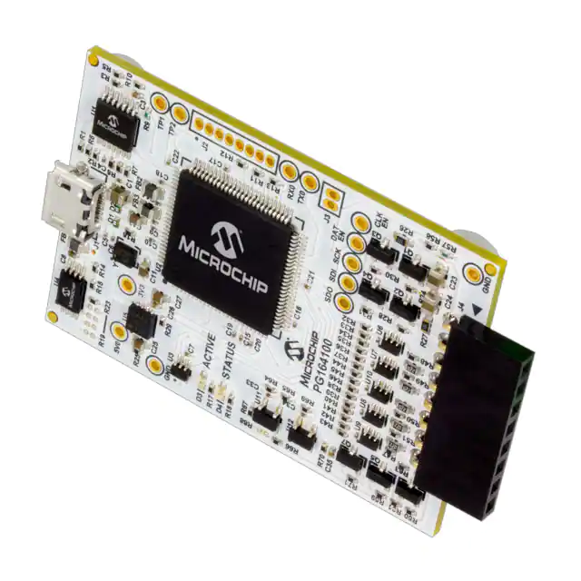
PG164100
Microchip Technology
-
ST-LINK/V2
STMicroelectronics
-
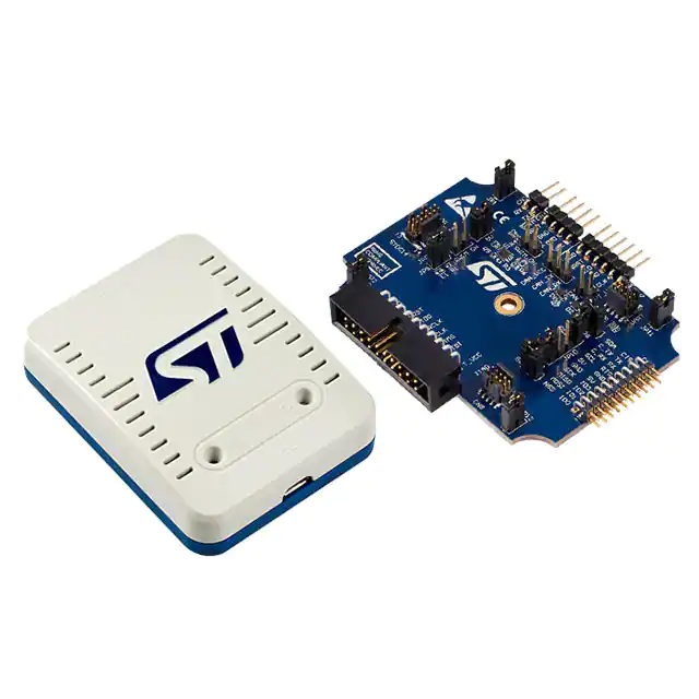
STLINK-V3SET
STMicroelectronics
-
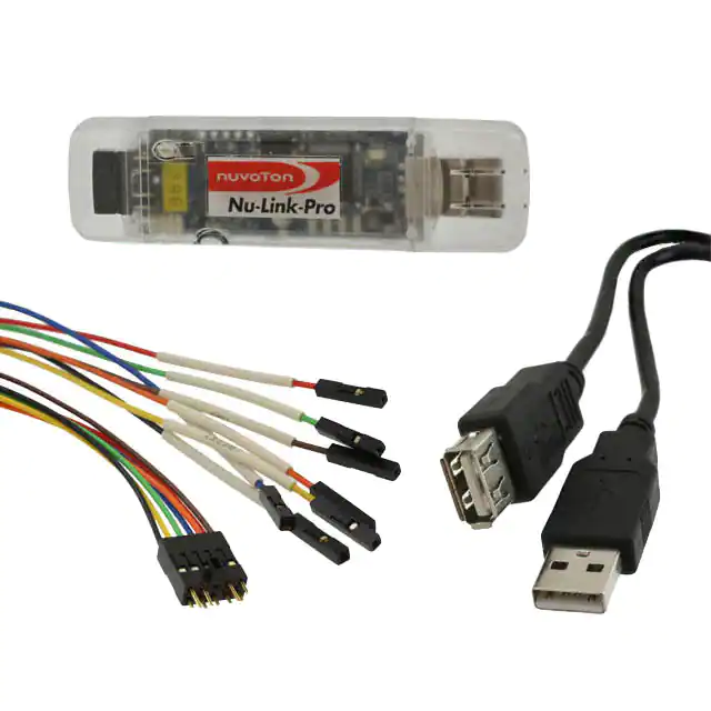
NU-LINK-PRO
Nuvoton Technology Corporation
-
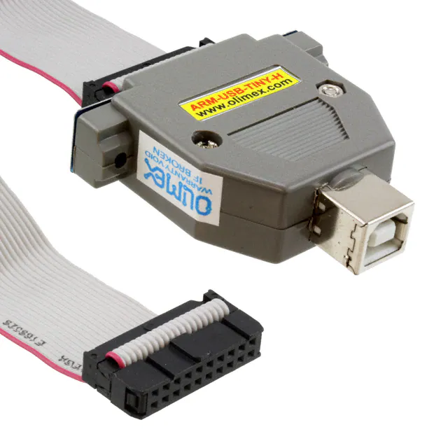
ARM-USB-TINY-H
Olimex LTD
-
MCU-LINK-PRO
NXP Semiconductors
-
410-308-B
Digilent, Inc.
Tech Hub

A practical engineering guide to 3.3V and 5V logic compatibility, input thresholds, resistor dividers, translator ICs, MOSFET level shifting, I2C pull-ups, timing limits and power-sequencing risks.

The 74HC595 uses push-pull logic outputs, while the TPIC6B595 uses 50 V open-drain DMOS sinks for higher-power loads. This guide compares timing, current limits, 3.3 V interfacing, load wiring, thermal…

The 74HC595 converts serial data into eight stable parallel outputs. This guide covers pin functions, shift and storage timing, OE and MR behavior, drive-current limits, cascading, voltage compatibilit…

A technical comparison of level-sensitive latches and edge-triggered flip-flops, covering timing windows, setup and hold limits, master–slave operation, time borrowing, race-through, HDL inference and…

A D latch stores one bit while Enable controls when data can pass. This reference covers gate-level operation, truth tables, transparency, setup and hold timing, LE versus OE, common ICs and practical …

An SR latch stores one bit through cross-coupled feedback. This engineering reference covers NOR and NAND implementations, truth tables, forbidden-state recovery, gated operation, switch debouncing, fa…

Latch circuits retain one bit through feedback. This technical reference covers SR and D latches, truth tables, transparency, timing limits, latch-versus-flip-flop behavior, applications and common log…

An engineering guide to LED driver operation, constant-current and constant-voltage outputs, linear and switching topologies, dimming, IC selection, calculations, replacement compatibility, and fault c…

Operational amplifier guide covering op amp basics, feedback, ideal vs real op amps, common configurations, buffer circuits, offset, bias current, gain-bandwidth, slew rate, rail-to-rail limits and sel…

Jumper cables guide covering safe connection order, red and black clamp placement, final ground connection, cable gauge, length, clamp quality, copper vs CCA cables, jump starter comparison and battery…


