
 My Inquiry
 My Account


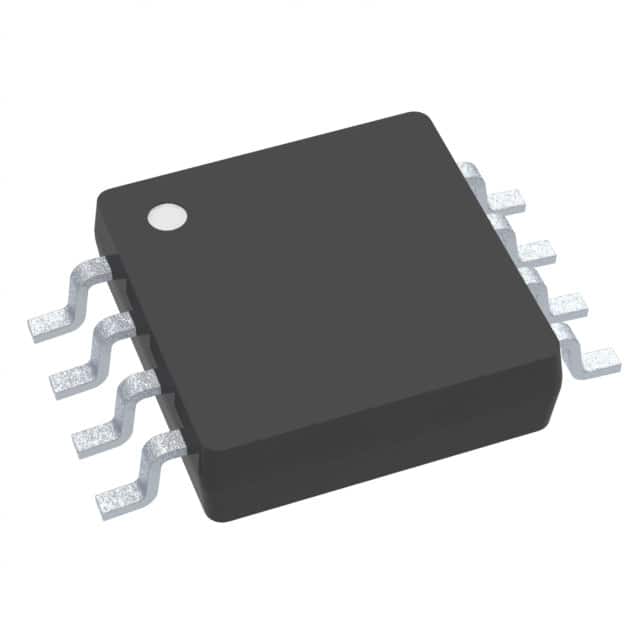
Texas Instruments TMP103FYFFR
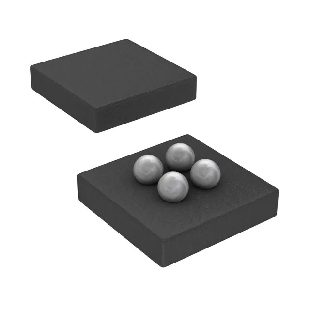
- Part No.:
- TMP103FYFFR
- Manufacturer:
- Texas Instruments
- Category:
- Analog and Digital Output
- Package:
- 4-UFBGA, DSBGA
- Datasheet:
-
 TMP103FYFFR.pdf
- Description:
- SENSOR DIGITAL -40C-125C 4DSBGA
- Quantity:
- Payment:

- Shipping:

Inventory:812
Please send an inquiry. Send us your inquiry, and we will respond immediately.
Product details
Overview
TMP103FYFFR from Texas Instruments is a low-power, digital temperature sensor in a 4-ball DSBGA (WCSP) package, featuring I²C/SMBus-compatible two-wire interface, ±1°C typical accuracy (–10°C to 100°C), 8-bit resolution, and 1.4 V to 3.6 V supply range. It serves as a system-level thermal monitor in space-constrained, battery-powered devices requiring multi-zone temperature profiling.
For engineers reviewing the TMP103FYFFR datasheet, TMP103FYFFR pinout, TMP103FYFFR application, or TMP103FYFFR equivalent, key selection criteria include its 26 ms conversion time, 1 μA shutdown current, MDA (Multiple Device Access) support for up to eight parallel sensors, and 0.76 mm × 0.76 mm WCSP footprint - all critical for thermal management in ultra-thin mobile and storage platforms.
Technical Context
The TMP103FYFFR implements a diode-based on-die temperature sensor with successive-approximation ADC, integrated oscillator, and programmable configuration register controlling conversion rate (0.25–8 Hz), shutdown/one-shot/continuous modes, and temperature window watchdog (THIGH/TLOW registers). Its serial interface supports both standard (≤400 kHz) and high-speed (≤3.4 MHz) I²C timing.
It operates across –40°C to 125°C, with thermal path optimized through metal bumps for accurate die-temperature measurement. The device uses a fixed 7-bit slave address (1110xxx per variant), where TMP103FYFFR corresponds to TMP103F (1110101), enabling deterministic multi-sensor bus addressing without external jumpers or resistors.
Key Specifications
| Parameter | Value and Actual Design Meaning |
|---|---|
| Supply Voltage | 1.4 V to 3.6 V - enables direct integration into single-cell Li-ion or coin-cell powered systems without LDO overhead |
| Accuracy | ±1°C typical (–10°C to 100°C) - sufficient for thermal throttling and battery health monitoring in consumer electronics |
| Resolution | 1°C (8-bit output) - provides discrete zone-level thermal state detection without oversampling complexity |
| Quiescent Current | 3 μA active (0.25 Hz), 1 μA shutdown - extends battery life in always-on thermal sensing nodes |
| Conversion Time | 26 ms typical - allows rapid response to thermal transients while maintaining low average power |
| Interface | I²C/SMBus-compatible two-wire - ensures interoperability with legacy and modern microcontrollers without protocol translation |
| Operating Temp | –40°C to 125°C - supports operation inside SSDs, baseband processors, and power management ICs |
Pinout & Package
Package: 4-ball DSBGA (YFF), 0.76 mm × 0.76 mm, 0.4 mm pitch, bottom-side solderable. Thermal resistance RθJA = 160°C/W enables passive thermal dissipation in thin PCB stacks.
| Pin/Terminal | Circuit Role | Design Meaning |
|---|---|---|
| A1 | V+ | Power supply input - requires local 0.01 μF bypass capacitor; no internal regulator |
| A2 | GND | Analog/digital ground reference - must be connected directly to PCB ground plane for accuracy |
| B1 | SDA | Open-drain bidirectional data line - requires external pullup (typically 2.2–10 kΩ) to V+ |
| B2 | SCL | Open-drain clock input - accepts standard I²C timing; integrated Schmitt trigger rejects bus noise |
Key Features
| Feature | Design Value |
|---|---|
| Multiple Device Access (MDA) | Enables global read/write to up to eight TMP103 sensors (e.g., TMP103F + TMP103A–E/G/H) with one command - reduces firmware overhead and bus traffic in multi-zone systems |
| Programmable Conversion Rate | Four selectable rates (0.25/1/4/8 Hz) via CR1/CR0 bits - balances responsiveness vs. power in thermal loop control |
| Temperature Window Watchdog | Configurable THIGH/TLOW registers with latchable FH/FL flags - triggers host interrupt on thermal excursion without polling |
| One-Shot Mode | Single conversion initiated from shutdown state - achieves <30 conversions/sec burst capability while preserving ultra-low standby current |
| Die-Temperature Sensing | Measures IC junction temperature directly via on-chip diode - ideal for SoC thermal monitoring and power rail derating |
Applications
| SSD Thermal Management | Notebook CPU Throttling |
|---|---|
Use Scenario: Monitoring NAND flash and controller die temperature during sustained write workloads to prevent data corruption and wear acceleration. IC Role / Device Role / Timing Role: Die-temperature sensor providing real-time feedback to SSD controller's thermal management firmware. Use Value: Enables dynamic throttling at ≤125°C junction limit using 26 ms conversion latency and ±1°C accuracy - avoids overdesign of heatsinking. | Use Scenario: Tracking CPU package temperature near VRM and memory subsystem to coordinate fan speed and performance scaling. IC Role / Device Role / Timing Role: Local thermal node feeding temperature data to EC or PMIC for closed-loop thermal control. Use Value: 1 μA shutdown current extends battery runtime during idle; MDA allows concurrent read of CPU/GPU/SSD sensors on shared bus. |
| Smartphone Baseband Thermal Profiling | Telecom Line Card Hot-Spot Detection |
Use Scenario: Measuring baseband processor and RF front-end temperature under cellular transmission bursts to maintain SAR compliance and signal integrity. IC Role / Device Role / Timing Role: Ultra-small-footprint thermal sensor placed adjacent to heat-generating ICs on compact PCBs. Use Value: 0.76 mm × 0.76 mm DSBGA footprint fits within tight board real estate; 1.4 V minimum supply supports direct connection to low-voltage rails. | Use Scenario: Detecting localized overheating on high-density line cards in carrier-grade switches/routers due to failed fans or blocked airflow. IC Role / Device Role / Timing Role: Distributed thermal sentinel reporting to system supervisor MCU via I²C bus. Use Value: Eight-address variants (e.g., TMP103F) allow unique identification of each sensor on shared bus - eliminates address conflict in modular chassis. |
Equivalent & Alternatives
The following parts are listed as comparable options for similar digital temperature sensor applications.
| Alternative Part | Technical Difference | Application Difference | Selection Advice |
|---|---|---|---|
| LM75BIMM/NOPB | 9-bit resolution, ±2°C accuracy (–25°C to 100°C), no MDA, larger MSOP-8 package (3 mm × 3 mm) | Lacks multi-sensor coordination; suited for single-point monitoring where size and ultra-low power are secondary | Choose when cost sensitivity outweighs footprint and power constraints; verify thermal accuracy tolerance in target operating range |
| MAX31875RTA+ | 16-bit resolution, ±0.25°C accuracy, 1.7–3.6 V supply, 6-pin WLP (1.5 mm × 1.5 mm), no MDA | Higher precision but larger footprint and no bus-wide command support - better for calibration-critical nodes than dense multi-zone arrays | Prefer for applications demanding sub-degree accuracy; avoid if MDA-driven firmware simplification or <1 mm² area budget is required |
Compared with LM75BIMM/NOPB and MAX31875RTA+, TMP103FYFFR delivers optimal trade-off of ultra-small size, multi-device bus efficiency, and microamp-level shutdown current - making it uniquely suitable for thermal-aware portable and embedded systems where board area and battery life are primary constraints.
Availability
TMP103FYFFR is available at Aetrix Electronics and suitable for SSD thermal management, notebook CPU throttling, smartphone baseband profiling, telecom line card monitoring, and set-top box environmental sensing requiring stable component supply across production lifecycles.
Supply support for TMP103FYFFR includes scheduled delivery planning, volume procurement assistance, BOM continuity management, traceable sourcing, and lifecycle availability coordination for OEM customers, industrial embedded developers, connected-device designers, and electronics production programs.
Manufacturer
Texas Instruments is a global semiconductor leader specializing in analog, embedded processing, and connectivity technologies, with decades of expertise in precision sensing and low-power design.
The TMP103 product line was engineered specifically for space-constrained, battery-operated systems needing reliable, multi-node thermal visibility - targeting mobile, storage, and infrastructure applications where traditional TO-92 or SOIC sensors are physically or energetically impractical.
FAQ
What is the exact I²C slave address for TMP103FYFFR?
The TMP103FYFFR corresponds to the TMP103F variant, with a fixed 7-bit I²C slave address of 1110101 (0x75 in hexadecimal). This address is hardwired and cannot be changed externally. The full 8-bit address byte sent by the master includes the R/W bit (0 for write, 1 for read), resulting in 0xEA for write and 0xEB for read operations. No external address pins or resistors are required.
Does TMP103FYFFR support SMBus Alert Response Address (ARA)?
No, TMP103FYFFR does not support SMBus Alert Response Address (ARA) functionality. It implements only standard I²C/SMBus slave protocols including general call reset and MDA commands, but lacks dedicated alert pin or ARA hardware. Thermal alerts must be polled via the FH/FL flag bits in the configuration register or detected through periodic register reads.
Can TMP103FYFFR measure ambient air temperature accurately?
TMP103FYFFR measures die temperature, not ambient air temperature. Its thermal path is dominated by conduction through solder bumps, making it highly sensitive to PCB and adjacent IC heating. For air temperature estimation, the device must be thermally isolated (e.g., mounted on thin flex, elevated above board) and calibrated against reference sensors - TI explicitly recommends avoiding direct air exposure for accuracy-critical use cases.
What is the maximum number of TMP103FYFFR devices that can share one I²C bus?
Up to eight TMP103 devices - including TMP103FYFFR - can operate on a single I²C bus using their unique factory-programmed addresses (TMP103A–H). The TMP103FYFFR (TMP103F) occupies address 0x75, leaving seven other addresses available. Bus capacitance and pullup strength must remain within I²C specification limits (≤400 pF total), typically requiring 2.2–4.7 kΩ pullups for eight devices.
Is there a recommended bypass capacitor value for TMP103FYFFR?
Yes, TI specifies a 0.01 μF ceramic bypass capacitor between V+ and GND, placed as close as possible to the TMP103FYFFR package balls. This capacitor stabilizes the supply during conversion events and suppresses high-frequency noise coupling from the I²C bus. Larger values (e.g., 0.1 μF) are not recommended, as they may slow voltage ramp-up during power-on and affect startup timing.
TMP103FYFFR Specifications
- Product attributes
- Attribute value
- Manufacturer:
- Texas Instruments
- Series:
- -
- Package/Case:
- 4-UFBGA, DSBGA
- Packaging:
- Tape & Reel (TR)
- Product Status:
- Active
- Sensor Type:
- Digital, Local
- Sensing Temperature - Local:
- -40°C ~ 125°C
- Sensing Temperature - Remote:
- -
- Output Type:
- I2C/SMBus
- Voltage - Supply:
- 1.4V ~ 3.6V
- Resolution:
- 8 b
- Features:
- One-Shot, Shutdown Mode
- Accuracy - Highest (Lowest):
- ±2°C (±3°C)
- Test Condition:
- -10°C ~ 100°C (-40°C ~ 125°C)
- Operating Temperature:
- -55°C ~ 150°C
- Mounting Type:
- Surface Mount
- Grade:
- -
- Qualification:
- -
- Supplier Device Package:
- 4-DSBGA (1x1)
TMP103FYFFR FAQ
1.How can I place an order for TMP103FYFFR through Aetrix?
Please submit a Request for Quotation (RFQ) for TMP103FYFFR on Aetrix. Our sales agent will provide a competitive quotation and guide you through the order confirmation once you accept the terms.
2.Are the price and stock information for TMP103FYFFR reliable?
The price and inventory of TMP103FYFFR are updated periodically and may fluctuate due to market conditions. Stock and pricing data are typically refreshed every 24 hours. Quotation validity for TMP103FYFFR is usually 5 days.
3.What payment methods are accepted for TMP103FYFFR?
We accept Wire Transfer, PayPal, Credit Card, Western Union, MoneyGram, and Escrow for TMP103FYFFR transactions.
Note: Certain payment methods may incur a processing fee.
4.How is shipping managed for TMP103FYFFR?
TMP103FYFFR orders can be shipped via leading logistics carriers, including DHL, UPS, FedEx, TNT, or Registered Mail.
Once your TMP103FYFFR order is processed, you will receive an email with the shipment details and tracking number.
Note: Tracking information may take up to 24 hours to appear. Express delivery typically takes 3–5 business days.
5.How can I obtain technical support or documentation for TMP103FYFFR?
For technical support, including TMP103FYFFR datasheets, pinout diagrams, or application guidance, please contact our engineering support team. They can provide detailed documentation and assistance for your TMP103FYFFR requirements.
6.How does Aetrix verify that TMP103FYFFR is sourced from the original manufacturer or authorized distributors?
All TMP103FYFFR products on Aetrix are procured from qualified distributors and authorized channels. Our dedicated quality assurance team conducts strict verification, including traceability checks and, if necessary, third-party testing. This ensures that TMP103FYFFR meets industry standards.
7.What is the process for return or replacement of TMP103FYFFR?
All TMP103FYFFR units undergo pre-shipment inspection (PSI). If there is an issue with TMP103FYFFR, returns or replacements are accepted under the following conditions:
1.Quantity discrepancies, incorrect items, or visible external defects (such as breakage or corrosion), acknowledged by Aetrix.
2.The issue is reported within 90 days of delivery.
3.The TMP103FYFFR part is unused and in its original packaging.
Return procedure for TMP103FYFFR:
1.Submit a request within 90 days.
2.Obtain a Return Material Authorization (RMA) from Aetrix.
TMP103FYFFR Tags
-
MCP9700T-E/TT
Microchip Technology
-
MCP9700T-E/LT
Microchip Technology
-
MCP9701T-E/TT
Microchip Technology
-
MCP9701T-E/LT
Microchip Technology

-
TMP235A4DBZR
Texas Instruments
-
MCP9700AT-E/TT
Microchip Technology
-
MCP9700AT-E/LT
Microchip Technology
-
MCP9701AT-E/LT
Microchip Technology
-
MCP9701AT-E/TT
Microchip Technology
,TO-226_straightlead.jpg)
-
LM335Z
STMicroelectronics
-
TMP1075NDRLR
Texas Instruments
-
TMP1075DGKR
Texas Instruments
Tech Hub

A practical engineering guide to 3.3V and 5V logic compatibility, input thresholds, resistor dividers, translator ICs, MOSFET level shifting, I2C pull-ups, timing limits and power-sequencing risks.

The 74HC595 uses push-pull logic outputs, while the TPIC6B595 uses 50 V open-drain DMOS sinks for higher-power loads. This guide compares timing, current limits, 3.3 V interfacing, load wiring, thermal…

The 74HC595 converts serial data into eight stable parallel outputs. This guide covers pin functions, shift and storage timing, OE and MR behavior, drive-current limits, cascading, voltage compatibilit…

A technical comparison of level-sensitive latches and edge-triggered flip-flops, covering timing windows, setup and hold limits, master–slave operation, time borrowing, race-through, HDL inference and…

A D latch stores one bit while Enable controls when data can pass. This reference covers gate-level operation, truth tables, transparency, setup and hold timing, LE versus OE, common ICs and practical …

An SR latch stores one bit through cross-coupled feedback. This engineering reference covers NOR and NAND implementations, truth tables, forbidden-state recovery, gated operation, switch debouncing, fa…

Latch circuits retain one bit through feedback. This technical reference covers SR and D latches, truth tables, transparency, timing limits, latch-versus-flip-flop behavior, applications and common log…

An engineering guide to LED driver operation, constant-current and constant-voltage outputs, linear and switching topologies, dimming, IC selection, calculations, replacement compatibility, and fault c…

Operational amplifier guide covering op amp basics, feedback, ideal vs real op amps, common configurations, buffer circuits, offset, bias current, gain-bandwidth, slew rate, rail-to-rail limits and sel…

Jumper cables guide covering safe connection order, red and black clamp placement, final ground connection, cable gauge, length, clamp quality, copper vs CCA cables, jump starter comparison and battery…


