
 My Inquiry
 My Account


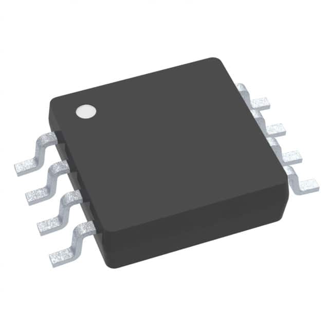
Texas Instruments TMP107BIDR
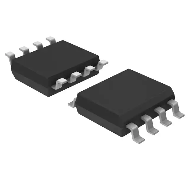
- Part No.:
- TMP107BIDR
- Manufacturer:
- Texas Instruments
- Category:
- Analog and Digital Output
- Package:
- 8-SOIC (0.154", 3.90mm Width)
- Datasheet:
-
 TMP107BIDR.pdf
- Description:
- SENSOR DIGITAL -55C-125C 8SOIC
- Quantity:
- Payment:

- Shipping:

Inventory:2,590
Please send an inquiry. Send us your inquiry, and we will respond immediately.
Product details
Overview
TMP107BIDR from Texas Instruments is a high-accuracy digital temperature sensor with bidirectional UART-compatible SMAART wire™ interface, 14-bit resolution (0.015625°C), ±0.4°C max accuracy from –20°C to +70°C, and dual open-drain ALERT outputs for over/undertemperature monitoring in distributed thermal sensing systems.
For engineers reviewing the TMP107BIDR datasheet, TMP107BIDR pinout, TMP107BIDR application, or TMP107BIDR equivalent, this page delivers verified electrical specs, daisy-chain timing constraints, EEPROM-programmable trip limits, SOIC-8 package layout, and real-world use cases in cold-chain logistics and industrial process control.
Technical Context
The TMP107BIDR implements a silicon-based temperature-sensing element with 14-bit ADC, integrated EEPROM for persistent device addressing and limit storage, and dual independent alert comparators with therm/alert mode selection. Its SMAART wire™ interface uses LSB-first 10-bit words (start + 8 data + stop) and supports up to 32 daisy-chained devices on a single wire at baud rates from 4.8 to 115.4 kBd.
Each device acquires a unique 5-bit address during automated address-initialize command execution, stored in EEPROM and restored after reset. The two ALERT pins (ALERT1/ALERT2) are open-drain outputs with internal 100-kΩ pullups (R1/R2), configurable as latched interrupts or transparent comparators, with polarity and hysteresis controlled via configuration register bits.
Key Specifications
| Parameter | Value and Actual Design Meaning |
|---|---|
| Accuracy | ±0.4°C max (–20°C to +70°C); enables precise thermal protection without calibration in server or battery management systems |
| Resolution | 14 bits (0.015625°C/LSB); supports fine-grained temperature trending in HVAC or medical diagnostics |
| Interface | UART-compatible SMAART wire™; single-wire daisy-chain up to 32 devices over 300 m, eliminating bus arbitration complexity |
| Alert Outputs | Dual open-drain ALERT1/ALERT2 with independent high/low limits; allows simultaneous monitoring of upper/lower thresholds per zone |
| Supply Range | 1.7 V to 5.5 V; interoperable with 1.8 V, 3.3 V, and 5 V microcontrollers without level-shifting |
| EEPROM | 100,000 write cycles, 10-year data retention; stores unique address, trip points, and user data for field-deployed sensor networks |
| Operating Temp | –55°C to +125°C; validated for extended operation in automotive under-hood, industrial motor control, and telecom base stations |
Pinout & Package
Package: SOIC-8 (4.90 mm × 3.90 mm), surface-mount, RoHS-compliant.
| Pin/Terminal | Circuit Role | Design Meaning |
|---|---|---|
| 1 - V+ | Power supply input | Accepts 1.7–5.5 V; powers internal analog/digital blocks and EEPROM; requires local 0.1 µF decoupling |
| 2 - R1 | ALERT1 pullup enable | Connect to V+ to activate internal 100-kΩ pullup; float if external pullup used; defines ALERT1 logic-high level |
| 3 - I/O1 | SMAART wire bidirectional data | Primary communication channel; supports full-duplex bit-banged or UART transceiver interface; 10-pF load timing critical |
| 4 - ALERT1 | Open-drain alert output | Asserts low when temperature exceeds programmed window; sinks up to 10 mA; requires external pullup if R1 floated |
| 5 - GND | Ground reference | Analog/digital common return; must be low-impedance path to minimize noise coupling into temperature measurement |
| 6 - ALERT2 | Open-drain alert output | Independent second alert channel; identical electrical behavior to ALERT1; enables dual-threshold or redundant monitoring |
| 7 - I/O2 | SMAART wire bidirectional data | Secondary communication channel; provides differential timing skew tolerance (33 ns avg phase shift vs I/O1) |
| 8 - R2 | ALERT2 pullup enable | Connect to V+ to activate internal 100-kΩ pullup; float if external pullup used; defines ALERT2 logic-high level |
Key Features
| Feature | Design Value |
|---|---|
| 14-bit temperature resolution | 0.015625°C step size enables detection of sub-degree thermal gradients in precision instrumentation |
| Dual programmable alert outputs | Independent high/low limits per ALERTx pin with latched or transparent modes reduce host polling overhead |
| EEPROM-stored device addressing | Automated 5-bit address assignment during daisy-chain initialization eliminates manual jumpers or DIP switches |
| Single-wire daisy-chain scalability | Supports up to 32 nodes on one bus with <1 µs edge jitter and 15% transition tolerance simplifies wiring in large-area deployments |
| Wide supply voltage range | 1.7–5.5 V operation allows direct integration with Li-ion battery packs (2.7–4.2 V) and industrial 3.3/5 V rails |
Applications
| Cold-Chain Logistics | Industrial Process Control |
|---|---|
Use Scenario: Monitoring temperature excursions across refrigerated transport containers, warehouse zones, and pharmaceutical storage units. IC Role / Device Role / Timing Role: Primary temperature sensor node in multi-drop SMAART wire™ network; reports real-time readings and triggers ALERT1 on threshold breach. Use Value: ±0.4°C accuracy ensures compliance with WHO GDP standards; EEPROM-stored trip points survive power loss during transit. |
Use Scenario: Thermal supervision of motors, pumps, and reactors in chemical plants and manufacturing lines. IC Role / Device Role / Timing Role: Distributed sensor at equipment hotspots; ALERT2 signals overtemperature to PLC via opto-isolated interface. Use Value: –55°C to +125°C operating range covers extreme ambient conditions; 100-kΩ internal pullups simplify field wiring. |
| Server & Telecom Thermal Management | Building Automation (HVAC) |
Use Scenario: Real-time CPU, memory, and power supply temperature tracking in rack-mounted servers and 5G baseband units. IC Role / Device Role / Timing Role: Node in daisy-chained thermal map; one-shot conversion mode minimizes self-heating during high-frequency polling. Use Value: 12–18 ms conversion time enables 55 Hz update rate; 3.8–10 µA shutdown current extends uptime in standby states. |
Use Scenario: Zonal temperature feedback for duct sensors, chiller monitoring, and boiler control in commercial HVAC systems. IC Role / Device Role / Timing Role: Remote sensor interfaced via long cable runs; SMAART wire™ tolerates 300 m inter-node distance with no repeaters. Use Value: Bidirectional UART compatibility allows reuse of existing UART firmware stacks; dual ALERTs support fail-safe high/low alarms. |
Equivalent & Alternatives
The following parts are listed as comparable options for similar digital temperature sensor applications.
| Alternative Part | Technical Difference | Application Difference | Selection Advice |
|---|---|---|---|
| MAX31820 | 1-Wire interface (not UART-compatible); 12-bit resolution (0.0625°C); ±0.5°C accuracy (–10°C to +85°C) | Limited to Dallas/Maxim 1-Wire ecosystem; no dual alerts or EEPROM-programmable addresses | Select MAX31820 only if legacy 1-Wire infrastructure exists and dual-alert functionality is unnecessary |
| DS18B20 | Parasitic-power capable; 12-bit resolution; ±0.5°C accuracy (–10°C to +85°C); no built-in EEPROM for addressing | Requires external pullup and power cycling for address resolution; lacks dedicated ALERT outputs | Choose DS18B20 for ultra-low-cost, parasitic-powered nodes where alert latency and EEPROM persistence are secondary |
Compared with MAX31820 and DS18B20, TMP107BIDR delivers higher resolution (14-bit), tighter accuracy (±0.4°C), dual independent alerts with EEPROM-stored limits, and UART-compatible SMAART wire™-enabling deterministic timing, longer cable runs, and simplified host firmware in scalable industrial networks.
Availability
TMP107BIDR is available at Aetrix Electronics and suitable for cold-chain logistics, industrial process control, and server thermal management requiring stable component supply, long-term lifecycle support, and traceable sourcing.
Supply support for TMP107BIDR includes scheduled delivery planning, volume procurement assistance, BOM continuity management, traceable sourcing, and lifecycle availability coordination for OEM customers, industrial embedded developers, connected-device designers, and electronics production programs.
Manufacturer
Texas Instruments is a global semiconductor leader specializing in analog, embedded processing, and connectivity technologies, with decades of expertise in precision sensing and industrial-grade IC design.
The TMP107BIDR belongs to TI's high-accuracy digital temperature sensor product line, engineered specifically for distributed, long-cable, multi-node thermal monitoring in harsh environments where reliability, EEPROM persistence, and deterministic communication are critical.
FAQ
What is the maximum daisy-chain length supported by TMP107BIDR?
The TMP107BIDR supports up to 32 daisy-chained devices on a single SMAART wire™ bus. This is enabled by its unique 5-bit EEPROM-stored addressing and robust UART-compatible protocol, which maintains signal integrity over distances up to 300 meters between consecutive nodes. Each TMP107BIDR automatically acquires its position-based address during the global address-initialize command, eliminating manual configuration.
How does TMP107BIDR handle power supply variations across its 1.7 V to 5.5 V range?
The TMP107BIDR maintains specified accuracy and timing across its full 1.7 V to 5.5 V supply range. Electrical characteristics-including temperature error (±0.4°C max), conversion time (12–18 ms), and quiescent current (16–400 µA)-are guaranteed over this range. Power-supply rejection is characterized in Figure 6 of the datasheet, showing minimal drift (<±0.1°C) from 1.7 V to 5.5 V at 25°C, ensuring stable operation in battery-backed or wide-input industrial supplies.
Can TMP107BIDR's ALERT1 and ALERT2 pins be used as general-purpose outputs?
Yes. When alert functionality is disabled by programming the high limit register to 7FFCh and low limit to 8000h, the ALERT1 and ALERT2 pins become controllable via polarity bits POL1 and POL2 in the configuration register. In this mode, TMP107BIDR effectively provides two open-drain GPIOs-useful for status signaling or driving external logic-while retaining all other sensor functions including temperature measurement and EEPROM access.
What is the role of R1 and R2 pins on TMP107BIDR, and how should they be connected?
R1 and R2 are dedicated control terminals for the internal 100-kΩ pullup resistors tied to ALERT1 and ALERT2, respectively. To use the internal pullups, connect R1 and R2 directly to V+. If external pullups are preferred (e.g., for different voltage levels or stronger drive), leave R1 and R2 floating. Incorrect connection-such as grounding R1/R2-disables the pullup and prevents ALERTx from asserting correctly.
Does TMP107BIDR require calibration for its stated ±0.4°C accuracy?
No. The ±0.4°C maximum accuracy from –20°C to +70°C is specified as "high accuracy without calibration" in the official datasheet (SBOS716D). This performance is achieved through factory-trimmed analog front-end and digital compensation algorithms. Users need not perform system-level calibration; however, application-specific thermal PCB layout and sensor mounting must follow TI's guidelines to maintain specified accuracy in end equipment.
TMP107BIDR Specifications
- Product attributes
- Attribute value
- Manufacturer:
- Texas Instruments
- Series:
- -
- Package/Case:
- 8-SOIC (0.154", 3.90mm Width)
- Packaging:
- Tape & Reel (TR)
- Product Status:
- Active
- Sensor Type:
- Digital, Local
- Sensing Temperature - Local:
- -55°C ~ 125°C
- Sensing Temperature - Remote:
- -
- Output Type:
- SMAART Wire
- Voltage - Supply:
- 1.7V ~ 5.5V
- Resolution:
- 14 b
- Features:
- One-Shot, Output Switch, Programmable Limit, Shutdown Mode
- Accuracy - Highest (Lowest):
- ±0.4°C (±0.7°C)
- Test Condition:
- -20°C ~ 70°C (-55°C ~ 125°C)
- Operating Temperature:
- -55°C ~ 125°C
- Mounting Type:
- Surface Mount
- Grade:
- -
- Qualification:
- -
- Supplier Device Package:
- 8-SOIC
TMP107BIDR FAQ
1.How can I place an order for TMP107BIDR through Aetrix?
Please submit a Request for Quotation (RFQ) for TMP107BIDR on Aetrix. Our sales agent will provide a competitive quotation and guide you through the order confirmation once you accept the terms.
2.Are the price and stock information for TMP107BIDR reliable?
The price and inventory of TMP107BIDR are updated periodically and may fluctuate due to market conditions. Stock and pricing data are typically refreshed every 24 hours. Quotation validity for TMP107BIDR is usually 5 days.
3.What payment methods are accepted for TMP107BIDR?
We accept Wire Transfer, PayPal, Credit Card, Western Union, MoneyGram, and Escrow for TMP107BIDR transactions.
Note: Certain payment methods may incur a processing fee.
4.How is shipping managed for TMP107BIDR?
TMP107BIDR orders can be shipped via leading logistics carriers, including DHL, UPS, FedEx, TNT, or Registered Mail.
Once your TMP107BIDR order is processed, you will receive an email with the shipment details and tracking number.
Note: Tracking information may take up to 24 hours to appear. Express delivery typically takes 3–5 business days.
5.How can I obtain technical support or documentation for TMP107BIDR?
For technical support, including TMP107BIDR datasheets, pinout diagrams, or application guidance, please contact our engineering support team. They can provide detailed documentation and assistance for your TMP107BIDR requirements.
6.How does Aetrix verify that TMP107BIDR is sourced from the original manufacturer or authorized distributors?
All TMP107BIDR products on Aetrix are procured from qualified distributors and authorized channels. Our dedicated quality assurance team conducts strict verification, including traceability checks and, if necessary, third-party testing. This ensures that TMP107BIDR meets industry standards.
7.What is the process for return or replacement of TMP107BIDR?
All TMP107BIDR units undergo pre-shipment inspection (PSI). If there is an issue with TMP107BIDR, returns or replacements are accepted under the following conditions:
1.Quantity discrepancies, incorrect items, or visible external defects (such as breakage or corrosion), acknowledged by Aetrix.
2.The issue is reported within 90 days of delivery.
3.The TMP107BIDR part is unused and in its original packaging.
Return procedure for TMP107BIDR:
1.Submit a request within 90 days.
2.Obtain a Return Material Authorization (RMA) from Aetrix.
TMP107BIDR Tags
-
MCP9700T-E/TT
Microchip Technology
-
MCP9700T-E/LT
Microchip Technology
-
MCP9701T-E/TT
Microchip Technology
-
MCP9701T-E/LT
Microchip Technology

-
TMP235A4DBZR
Texas Instruments
-
MCP9700AT-E/TT
Microchip Technology
-
MCP9700AT-E/LT
Microchip Technology
-
MCP9701AT-E/LT
Microchip Technology
-
MCP9701AT-E/TT
Microchip Technology
,TO-226_straightlead.jpg)
-
LM335Z
STMicroelectronics
-
TMP1075NDRLR
Texas Instruments
-
TMP1075DGKR
Texas Instruments
Tech Hub

A practical engineering guide to 3.3V and 5V logic compatibility, input thresholds, resistor dividers, translator ICs, MOSFET level shifting, I2C pull-ups, timing limits and power-sequencing risks.

The 74HC595 uses push-pull logic outputs, while the TPIC6B595 uses 50 V open-drain DMOS sinks for higher-power loads. This guide compares timing, current limits, 3.3 V interfacing, load wiring, thermal…

The 74HC595 converts serial data into eight stable parallel outputs. This guide covers pin functions, shift and storage timing, OE and MR behavior, drive-current limits, cascading, voltage compatibilit…

A technical comparison of level-sensitive latches and edge-triggered flip-flops, covering timing windows, setup and hold limits, master–slave operation, time borrowing, race-through, HDL inference and…

A D latch stores one bit while Enable controls when data can pass. This reference covers gate-level operation, truth tables, transparency, setup and hold timing, LE versus OE, common ICs and practical …

An SR latch stores one bit through cross-coupled feedback. This engineering reference covers NOR and NAND implementations, truth tables, forbidden-state recovery, gated operation, switch debouncing, fa…

Latch circuits retain one bit through feedback. This technical reference covers SR and D latches, truth tables, transparency, timing limits, latch-versus-flip-flop behavior, applications and common log…

An engineering guide to LED driver operation, constant-current and constant-voltage outputs, linear and switching topologies, dimming, IC selection, calculations, replacement compatibility, and fault c…

Operational amplifier guide covering op amp basics, feedback, ideal vs real op amps, common configurations, buffer circuits, offset, bias current, gain-bandwidth, slew rate, rail-to-rail limits and sel…

Jumper cables guide covering safe connection order, red and black clamp placement, final ground connection, cable gauge, length, clamp quality, copper vs CCA cables, jump starter comparison and battery…


