
 My Inquiry
 My Account


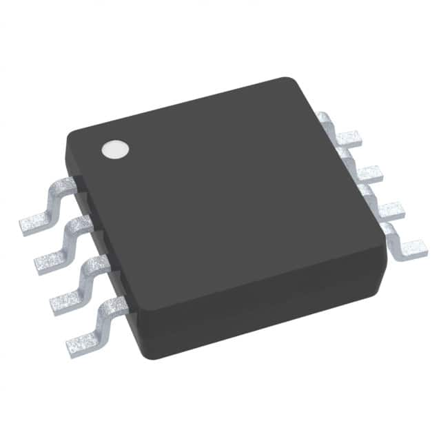
Texas Instruments TMP107BQDRQ1
- Part No.:
- TMP107BQDRQ1
- Manufacturer:
- Texas Instruments
- Category:
- Analog and Digital Output
- Package:
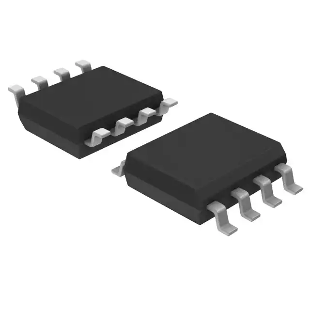
- 8-SOIC (0.154", 3.90mm Width)
- Datasheet:
-
 TMP107BQDRQ1.pdf
- Description:
- SENSOR DIGITAL -55C-125C 8SOIC
- Quantity:
- Payment:

- Shipping:

Inventory:2,500
Please send an inquiry. Send us your inquiry, and we will respond immediately.
Product details
Overview
TMP107BQDRQ1 from Texas Instruments is an AEC-Q100 Grade 1 automotive digital temperature sensor with daisy-chain UART (SMAART wire™) interface, ±0.4°C accuracy from –20°C to +70°C, 14-bit resolution (0.015625°C), and dual open-drain ALERT outputs - deployed in battery management systems for real-time cell temperature monitoring across long cable runs.
For engineers reviewing the TMP107BQDRQ1 datasheet, TMP107BQDRQ1 pinout, TMP107BQDRQ1 application, or TMP107BQDRQ1 equivalent, this page delivers verified electrical specs, daisy-chain timing constraints, EEPROM-programmable alert thresholds, SOIC-8 package layout guidance, and validated alternatives for distributed thermal sensing in harsh automotive environments.
Technical Context
The TMP107BQDRQ1 implements a silicon-based temperature-sensing element with on-chip ADC and UART-compatible SMAART wire™ physical layer, enabling up to 32 devices on a single-wire bus over 300 m. Its dual ALERT pins support independent high/low limit detection with latched or transparent comparator modes.
Each device stores a unique 5-bit address in internal EEPROM after automated address initialization; conversion timing is programmable from 1/16 to 62 conversions/sec, and quiescent current ranges from 3.8 μA (shutdown) to 400 μA (active, bus idle) at 3.3 V.
Key Specifications
| Parameter | Value and Actual Design Meaning |
|---|---|
| Accuracy | ±0.4°C max from –20°C to +70°C - enables direct replacement of NTC thermistors without system-level calibration in BMS cold-junction compensation. |
| Resolution | 14-bit (0.015625°C LSB) - supports fine-grained thermal gradient tracking across multi-cell battery packs. |
| Interface | SMAART wire™ (UART-compatible, single-wire, daisy-chain) - eliminates routing complexity vs I²C/SPI in distributed sensor networks. |
| Alert Outputs | Dual open-drain ALERT1/ALERT2 with internal 100-kΩ pullups (R1/R2) - simplifies PCB design by removing external resistors unless higher sink current (>10 mA) required. |
| Supply Range | 1.7 V to 5.5 V - interoperates with 3.3 V microcontrollers and 5 V legacy automotive domains without level-shifting. |
| Operating Temp | –55°C to +125°C ambient - qualified per AEC-Q100 Grade 1 for under-hood and traction battery applications. |
| EEPROM | 100,000 write cycles, 10-year data retention - stores unique address, trip limits, and configuration persistently across power cycles. |
Pinout & Package
Package: SOIC-8 (4.90 mm × 3.90 mm), surface-mount, RoHS-compliant.
| Pin/Terminal | Circuit Role | Design Meaning |
|---|---|---|
| V+ | Power supply input | Accepts 1.7–5.5 V; powers internal regulator, ADC, and SMAART wire transceiver - decoupling capacitor (0.1 µF) required adjacent to pin. |
| GND | Ground reference | Primary return path for analog and digital circuits; must connect to low-impedance system ground plane. |
| I/O1, I/O2 | Half-duplex SMAART wire bidirectional data | I/O1 = host-facing input/output; I/O2 = downstream daisy-chain output - both require 10-pF load compliance and 10 ns rise/fall times. |
| ALERT1, ALERT2 | Open-drain alert outputs | Assert low when temperature exceeds programmed limits; internally tied to R1/R2 pullups - float R1/R2 if using external pullups. |
| R1, R2 | Internal pullup enable terminals | Connect to V+ to activate internal 100-kΩ pullups for ALERT1/ALERT2; leave floating if external pullups used. |
Key Features
| Feature | Design Value |
|---|---|
| Daisy-chain scalability | Up to 32 devices on one SMAART wire bus - reduces wiring harness weight and ECU GPIO count in multi-zone thermal monitoring. |
| Programmable alert modes | Configurable latched (alert mode) or transparent (therm mode) behavior per ALERT pin - supports both fault logging and real-time overtemperature shutdown. |
| One-shot conversion | 12–18 ms typical conversion time - minimizes self-heating error and enables precise timing control in duty-cycled sensing applications. |
| Shutdown current | 3.8 μA max at –55°C to +125°C - extends battery life in always-on vehicle subsystems like 12 V telematics modules. |
| AEC-Q100 qualification | Grade 1 (–40°C to +125°C), HBM ±2 kV, CDM ±1 kV - meets automotive reliability requirements without additional qualification testing. |
Applications
| Battery Management Systems (BMS) | Hybrid/Electric Powertrain Thermal Monitoring |
|---|---|
Use Scenario: Real-time cell temperature acquisition across 12–96 series-connected Li-ion cells in high-voltage traction battery packs. IC Role / Device Role / Timing Role: Primary temperature sensor node in daisy-chained topology; reports 14-bit readings via SMAART wire to master MCU every 100 ms. Use Value: ±0.4°C accuracy ensures safe charge/discharge control within JEITA limits; 300 m bus reach allows centralized placement of BMS controller away from high-EMI battery zones. | Use Scenario: Distributed thermal sensing on inverter IGBT heatsinks, DC-DC converter transformers, and motor stator windings. IC Role / Device Role / Timing Role: Localized thermal watchdog feeding into torque derating algorithms; ALERT2 triggers immediate PWM shutdown on >110°C detection. Use Value: Dual independent alerts eliminate need for external comparators; EEPROM-stored trip points survive power loss during crash events. |
| Body Control Modules (BCMs) | Diesel Exhaust Fluid (DEF) Tank Monitoring |
Use Scenario: Cabin ambient and HVAC duct temperature feedback for climate control logic in premium vehicle platforms. IC Role / Device Role / Timing Role: Secondary sensor node in multi-drop SMAART wire network; shares bus with door module and seat heater sensors. Use Value: SOIC-8 package fits tight BCM PCB space; 1.7 V operation supports stop-start battery voltage sag without reset. | Use Scenario: Freeze-protection monitoring of DEF fluid in SCR aftertreatment systems operating down to –40°C. IC Role / Device Role / Timing Role: Standalone temperature node with ALERT1 wired to engine ECU as wake-up interrupt on sub-zero detection. Use Value: –55°C to +125°C range covers DEF crystallization (–11°C) and exhaust heat soak; ±0.7°C accuracy at extremes prevents false urea dosing. |
Equivalent & Alternatives
The following parts are listed as comparable options for similar automotive temperature sensing applications.
| Alternative Part | Technical Difference | Application Difference | Selection Advice |
|---|---|---|---|
| LM75BIMM/NOPB | I²C interface, no daisy-chain, ±2°C accuracy, no EEPROM, 8-pin VSSOP | Limited to point sensing; requires dedicated I²C lines per sensor or multiplexer in multi-node setups | Select only for cost-sensitive non-automotive designs where daisy-chain and <±0.5°C accuracy are unnecessary. |
| MAX31820MUA+ | 1-Wire interface, ±0.5°C accuracy, no dual alerts, TO-92 package, no AEC-Q100 | Requires external pullup; lacks automotive qualification and programmable alert latching; unsuitable for safety-critical BMS | Consider only for industrial prototypes where automotive qualification and dual-alert redundancy are not mandated. |
Compared with LM75BIMM/NOPB and MAX31820MUA+, the TMP107BQDRQ1 uniquely combines AEC-Q100 Grade 1 qualification, daisy-chain scalability, dual independently configurable alerts, and EEPROM-persistent addressing - making it the only option for production automotive thermal networks requiring traceability, fault isolation, and long-cable robustness.
Availability
TMP107BQDRQ1 is available at Aetrix Electronics and suitable for battery management systems, hybrid/electric powertrain controls, and body control modules requiring stable component supply across extended automotive product lifecycles.
Supply support for TMP107BQDRQ1 includes scheduled delivery planning, volume procurement assistance, BOM continuity management, traceable sourcing, and lifecycle availability coordination for OEM customers, industrial embedded developers, connected-device designers, and electronics production programs.
Manufacturer
Texas Instruments is a global semiconductor company headquartered in Dallas, Texas, delivering analog and embedded processing solutions for automotive, industrial, and personal electronics markets.
The TMP107-Q1 product line was engineered specifically for distributed, high-reliability temperature monitoring in automotive subsystems - emphasizing daisy-chain scalability, EEPROM-configurable alerting, and AEC-Q100 compliance without external components.
FAQ
What is the maximum daisy-chain length supported by TMP107BQDRQ1?
The TMP107BQDRQ1 supports up to 32 devices on a single SMAART wire™ bus, with reliable communication over distances up to 300 meters between consecutive nodes. This capability is validated per TI's SBOS726A datasheet and enables scalable thermal monitoring in large battery packs or chassis-wide sensor networks without repeaters or protocol translation.
How does TMP107BQDRQ1 store its unique device address?
The TMP107BQDRQ1 stores its unique 5-bit device address in on-chip EEPROM memory after execution of the global address-initialize command. This address persists across power cycles and resets, eliminating the need for external address configuration hardware or firmware boot-time enumeration in production systems.
Can TMP107BQDRQ1 operate with a 1.7 V supply in automotive stop-start conditions?
Yes, TMP107BQDRQ1 operates reliably from 1.7 V to 5.5 V per its recommended conditions. At 1.7 V, it maintains full functionality including 14-bit conversion, ALERT output sinking, and SMAART wire™ communication at reduced baud rates - making it suitable for automotive stop-start battery voltage sags where nominal 12 V drops to ~6–8 V (regulated to 1.7 V).
What is the purpose of R1 and R2 pins on TMP107BQDRQ1?
R1 and R2 are internal pullup enable terminals for ALERT1 and ALERT2, respectively. Connecting R1/R2 to V+ activates the integrated 100-kΩ pullup resistors; leaving them floating disables the internal pullups, allowing use of external resistors for higher sink current or custom voltage levels - a key flexibility for interfacing with diverse ECU input thresholds.
Does TMP107BQDRQ1 require calibration to achieve ±0.4°C accuracy?
No, TMP107BQDRQ1 achieves ±0.4°C maximum accuracy from –20°C to +70°C without system-level calibration. This specification is guaranteed over process, voltage, and temperature (PVT) variations and is factory-trimmed - enabling drop-in replacement of analog thermistors in automotive BMS and powertrain applications.
TMP107BQDRQ1 Specifications
- Product attributes
- Attribute value
- Manufacturer:
- Texas Instruments
- Series:
- -
- Package/Case:
- 8-SOIC (0.154", 3.90mm Width)
- Packaging:
- Tape & Reel (TR)
- Product Status:
- Active
- Sensor Type:
- Digital, Local
- Sensing Temperature - Local:
- -55°C ~ 125°C
- Sensing Temperature - Remote:
- -
- Output Type:
- SMAART Wire
- Voltage - Supply:
- 1.7V ~ 5.5V
- Resolution:
- 14 b
- Features:
- One-Shot, Output Switch, Programmable Limit, Shutdown Mode
- Accuracy - Highest (Lowest):
- ±0.4°C (±0.7°C)
- Test Condition:
- -20°C ~ 70°C (-55°C ~ 125°C)
- Operating Temperature:
- -55°C ~ 125°C
- Mounting Type:
- Surface Mount
- Grade:
- Automotive
- Qualification:
- AEC-Q100
- Supplier Device Package:
- 8-SOIC
TMP107BQDRQ1 FAQ
1.How can I place an order for TMP107BQDRQ1 through Aetrix?
Please submit a Request for Quotation (RFQ) for TMP107BQDRQ1 on Aetrix. Our sales agent will provide a competitive quotation and guide you through the order confirmation once you accept the terms.
2.Are the price and stock information for TMP107BQDRQ1 reliable?
The price and inventory of TMP107BQDRQ1 are updated periodically and may fluctuate due to market conditions. Stock and pricing data are typically refreshed every 24 hours. Quotation validity for TMP107BQDRQ1 is usually 5 days.
3.What payment methods are accepted for TMP107BQDRQ1?
We accept Wire Transfer, PayPal, Credit Card, Western Union, MoneyGram, and Escrow for TMP107BQDRQ1 transactions.
Note: Certain payment methods may incur a processing fee.
4.How is shipping managed for TMP107BQDRQ1?
TMP107BQDRQ1 orders can be shipped via leading logistics carriers, including DHL, UPS, FedEx, TNT, or Registered Mail.
Once your TMP107BQDRQ1 order is processed, you will receive an email with the shipment details and tracking number.
Note: Tracking information may take up to 24 hours to appear. Express delivery typically takes 3–5 business days.
5.How can I obtain technical support or documentation for TMP107BQDRQ1?
For technical support, including TMP107BQDRQ1 datasheets, pinout diagrams, or application guidance, please contact our engineering support team. They can provide detailed documentation and assistance for your TMP107BQDRQ1 requirements.
6.How does Aetrix verify that TMP107BQDRQ1 is sourced from the original manufacturer or authorized distributors?
All TMP107BQDRQ1 products on Aetrix are procured from qualified distributors and authorized channels. Our dedicated quality assurance team conducts strict verification, including traceability checks and, if necessary, third-party testing. This ensures that TMP107BQDRQ1 meets industry standards.
7.What is the process for return or replacement of TMP107BQDRQ1?
All TMP107BQDRQ1 units undergo pre-shipment inspection (PSI). If there is an issue with TMP107BQDRQ1, returns or replacements are accepted under the following conditions:
1.Quantity discrepancies, incorrect items, or visible external defects (such as breakage or corrosion), acknowledged by Aetrix.
2.The issue is reported within 90 days of delivery.
3.The TMP107BQDRQ1 part is unused and in its original packaging.
Return procedure for TMP107BQDRQ1:
1.Submit a request within 90 days.
2.Obtain a Return Material Authorization (RMA) from Aetrix.
TMP107BQDRQ1 Tags
-
MCP9700T-E/TT
Microchip Technology
-
MCP9700T-E/LT
Microchip Technology
-
MCP9701T-E/TT
Microchip Technology
-
MCP9701T-E/LT
Microchip Technology

-
TMP235A4DBZR
Texas Instruments
-
MCP9700AT-E/TT
Microchip Technology
-
MCP9700AT-E/LT
Microchip Technology
-
MCP9701AT-E/LT
Microchip Technology
-
MCP9701AT-E/TT
Microchip Technology
,TO-226_straightlead.jpg)
-
LM335Z
STMicroelectronics
-
TMP1075NDRLR
Texas Instruments
-
TMP1075DGKR
Texas Instruments
Tech Hub

A practical engineering guide to 3.3V and 5V logic compatibility, input thresholds, resistor dividers, translator ICs, MOSFET level shifting, I2C pull-ups, timing limits and power-sequencing risks.

The 74HC595 uses push-pull logic outputs, while the TPIC6B595 uses 50 V open-drain DMOS sinks for higher-power loads. This guide compares timing, current limits, 3.3 V interfacing, load wiring, thermal…

The 74HC595 converts serial data into eight stable parallel outputs. This guide covers pin functions, shift and storage timing, OE and MR behavior, drive-current limits, cascading, voltage compatibilit…

A technical comparison of level-sensitive latches and edge-triggered flip-flops, covering timing windows, setup and hold limits, master–slave operation, time borrowing, race-through, HDL inference and…

A D latch stores one bit while Enable controls when data can pass. This reference covers gate-level operation, truth tables, transparency, setup and hold timing, LE versus OE, common ICs and practical …

An SR latch stores one bit through cross-coupled feedback. This engineering reference covers NOR and NAND implementations, truth tables, forbidden-state recovery, gated operation, switch debouncing, fa…

Latch circuits retain one bit through feedback. This technical reference covers SR and D latches, truth tables, transparency, timing limits, latch-versus-flip-flop behavior, applications and common log…

An engineering guide to LED driver operation, constant-current and constant-voltage outputs, linear and switching topologies, dimming, IC selection, calculations, replacement compatibility, and fault c…

Operational amplifier guide covering op amp basics, feedback, ideal vs real op amps, common configurations, buffer circuits, offset, bias current, gain-bandwidth, slew rate, rail-to-rail limits and sel…

Jumper cables guide covering safe connection order, red and black clamp placement, final ground connection, cable gauge, length, clamp quality, copper vs CCA cables, jump starter comparison and battery…


