
 My Inquiry
 My Account


Texas Instruments TMP114NAIYMTT
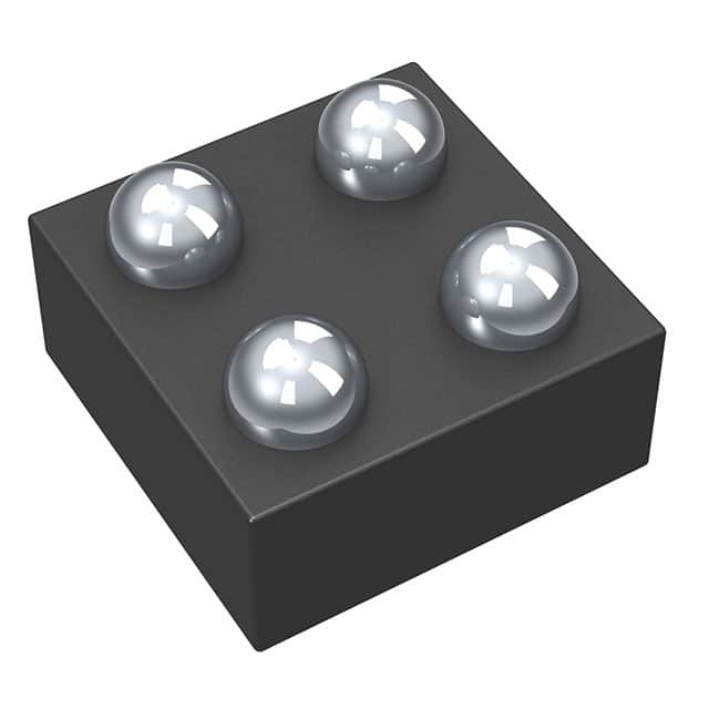
- Part No.:
- TMP114NAIYMTT
- Manufacturer:
- Texas Instruments
- Category:
- Analog and Digital Output
- Package:
- 4-XFBGA, DSBGA
- Datasheet:
-
 TMP114NAIYMTT.pdf
- Description:
- 0.15-MM HEIGHT, 1.2-V CAPABLE TE
- Quantity:
- Payment:

- Shipping:

Inventory:750
Please send an inquiry. Send us your inquiry, and we will respond immediately.
Product details
Overview
TMP114NAIYMTT from Texas Instruments is a high-accuracy, ultra-thin digital temperature sensor with I²C/SMBus interface, ±0.2°C accuracy from 20°C to 50°C, 16-bit resolution (0.0078°C LSB), and operation from 1.08 V to 1.98 V supply - deployed in mobile phones and SSDs for real-time thermal monitoring.
For engineers reviewing the TMP114NAIYMTT datasheet, TMP114NAIYMTT pinout, TMP114NAIYMTT application, or TMP114NAIYMTT equivalent, key selection criteria include its 0.15-mm DSBGA package height, NIST-traceable calibration, 300-ms liquid response time, 0.7 µA average current in continuous mode, and 1.2-V logic compatibility independent of VDD.
Technical Context
The TMP114NAIYMTT integrates a precision bandgap-based thermal sensing element with a 16-bit sigma-delta ADC and on-chip oscillator, delivering factory-calibrated output without external compensation. Its digital core supports both continuous and one-shot conversion modes, with configurable averaging (AVG=0/1) and conversion periods ranging from 31.25 ms to 2 s.
It implements an optional 8-bit CRC for I²C data integrity, slew-rate warning detection using consecutive temperature deltas, and dual alert thresholds with programmable hysteresis. The device uses static 1.2-V-compatible input thresholds on SDA/SCL, enabling interoperability across mixed-voltage I²C buses without level shifters.
Key Specifications
| Parameter | Value and Actual Design Meaning |
|---|---|
| Accuracy (20°C–50°C) | ±0.2°C maximum - enables precise thermal throttling in battery-powered devices without software correction |
| Supply Voltage Range | 1.08 V to 1.98 V - supports direct connection to 1.2-V and 1.8-V rails in modern SoC subsystems |
| Resolution | 16-bit (0.0078°C LSB) - provides sub-millidegree granularity for closed-loop thermal control algorithms |
| Average Current (1 Hz) | 0.63 µA (TYP) - extends multi-year battery life in wearables and always-on sensors |
| Response Time (liquid) | 300 ms (τ = 63%) - ensures rapid detection of thermal transients on flex PCBs |
| Package Height | 0.15 mm - allows placement under stacked components or beneath display layers |
| I²C Compatibility | Standard/Fast/Fast-Plus modes with 50-ns spike filter - coexists reliably on I³C-mixed buses |
Pinout & Package
Package: 4-ball DSBGA (PicoStar™), 0.76 mm × 0.76 mm, 0.15-mm profile - optimized for volume-constrained portable electronics.
| Pin/Terminal | Circuit Role | Design Meaning |
|---|---|---|
| VDD | Power supply input | Accepts 1.08–1.98 V; powers internal analog/digital blocks and enables 1.2-V logic compatibility |
| GND | Ground reference | Common return path for sensor core, ADC, and I²C interface; critical for noise immunity |
| SDA | Open-drain bidirectional data line | Supports I²C read/write with optional CRC; requires external pullup; tolerates 2.1-V max |
| SCL | Input-only clock line | Drives internal timing; static VIH/VIL thresholds ensure robustness across supply voltage variations |
Key Features
| Feature | Design Value |
|---|---|
| NIST-traceable calibration | 100% production-tested against ISO/IEC 17025-accredited standards - eliminates need for system-level recalibration |
| Adjustable conversion period | Configurable from 31.25 ms to 2 s via Conv_Period[1:0] bits - balances update rate vs. power in thermal management loops |
| Programmable slew-rate warning | Detects rapid ΔT/dt > Slew_Limit (unsigned) - triggers early thermal intervention before critical limits are breached |
| Temperature alert with hysteresis | Separate THigh/TLow registers + 0.1°C hysteresis - prevents alert chatter during marginal thermal excursions |
| Ultra-low shutdown current | 0.16 µA (TYP) at 25°C - enables microampere-level sleep states in always-on monitoring applications |
Applications
| Mobile Phones | Solid State Drives (SSDs) |
|---|---|
Use Scenario: Real-time die temperature monitoring of application processors and RF front-end modules during burst workloads. IC Role / Device Role / Timing Role: Primary thermal sensor feeding OS thermal manager; updates every 100 ms in continuous mode. Use Value: Enables dynamic frequency scaling before junction temperatures exceed 105°C, preserving performance and reliability. | Use Scenario: Monitoring NAND flash and controller die temperature during sustained write operations. IC Role / Device Role / Timing Role: Embedded thermal guardrail sensor; alerts host controller when temperature exceeds 70°C threshold. Use Value: Prevents write amplification errors and data retention loss by triggering throttling before NAND thermal derating begins. |
| Wearable Fitness Monitors | IP Cameras |
Use Scenario: Skin-contact temperature measurement during heart-rate and activity tracking sessions. IC Role / Device Role / Timing Role: Low-power, one-shot temperature acquisition synchronized with motion sensor wake events. Use Value: Achieves ±0.2°C accuracy at skin interface while consuming <1 µA average current over 24-hour cycles. | Use Scenario: Monitoring image sensor and ISP die temperature in enclosed outdoor enclosures subject to solar heating. IC Role / Device Role / Timing Role: Continuous thermal watchdog; initiates fan control or frame-rate reduction upon crossing 85°C. Use Value: Maintains CMOS image sensor dark current stability and prevents thermal-induced image noise degradation. |
Equivalent & Alternatives
The following parts are listed as comparable options for similar digital temperature sensor applications.
| Alternative Part | Technical Difference | Application Difference | Selection Advice |
|---|---|---|---|
| TMP117AIYFFR | ±0.1°C max accuracy (0°C–70°C); 32-bit resolution; 0.8-mm × 0.8-mm DSBGA; 1.7-µA avg current | Higher precision required for medical-grade thermometry; larger footprint and higher power limit use in ultra-thin wearables | Select TMP117AIYFFR only if sub-0.2°C accuracy and long-term drift <0.01°C/year are mandatory |
| MAX31875CATB+ | ±1.0°C accuracy; 12-bit resolution; 1.5-mm × 1.5-mm WLP; supports SMBus Alert Response Address | Lower-cost thermal protection in industrial controllers where ±1°C tolerance is acceptable | Choose MAX31875CATB+ when cost sensitivity outweighs accuracy needs and board space permits larger package |
Compared with TMP114NAIYMTT, TMP117AIYFFR delivers tighter accuracy but increases average current by 2.7× and raises BOM cost; MAX31875CATB+ reduces cost and simplifies alert handling but sacrifices 0.8°C absolute accuracy and 4-bit resolution - making TMP114NAIYMTT optimal for space-constrained, battery-sensitive consumer electronics requiring verified ±0.2°C performance.
Availability
TMP114NAIYMTT is available at Aetrix Electronics and suitable for mobile phones, solid state drives (SSDs), and wearable fitness monitors requiring stable component supply, long-lifecycle support, and traceable NIST-calibrated performance.
Supply support for TMP114NAIYMTT includes scheduled delivery planning, volume procurement assistance, BOM continuity management, traceable sourcing, and lifecycle availability coordination for OEM customers, industrial embedded developers, connected-device designers, and electronics production programs.
Manufacturer
Texas Instruments is a global semiconductor company specializing in analog and embedded processing technologies, with leadership in precision sensing, low-power design, and automotive-grade reliability.
The TMP114 product line targets ultra-thin, battery-operated consumer electronics requiring high-accuracy, low-power thermal monitoring - designed specifically for integration beneath displays, under stacked ICs, and into flex-based wearable platforms.
FAQ
What is the operating temperature range of the TMP114NAIYMTT?
The TMP114NAIYMTT operates across –40°C to +125°C. Within this full range, its accuracy is specified as ±0.5°C maximum; tighter tolerances apply in narrower bands: ±0.2°C from 20°C to 50°C and ±0.3°C from –10°C to 80°C. This graded specification reflects factory calibration across multiple temperature points using NIST-traceable equipment, ensuring reliable thermal feedback in both ambient and high-stress environments where the TMP114NAIYMTT is deployed.
Does the TMP114NAIYMTT support I²C Fast Mode Plus timing?
Yes, the TMP114NAIYMTT supports I²C Fast Mode Plus with up to 1 MHz clock frequency (fSCL), meeting tLOW/tHIGH ≤ 0.26 µs and tVDAT ≤ 150 ns requirements. It also includes a 50-ns spike filter on SDA/SCL lines, enabling robust coexistence on mixed-signal I³C buses. The device maintains static 1.2-V logic thresholds regardless of VDD, allowing seamless interface with 1.2-V or 1.8-V controllers - a key capability confirmed in the TMP114NAIYMTT's official timing tables and functional description.
How does the TMP114NAIYMTT achieve ±0.2°C accuracy without system-level calibration?
The TMP114NAIYMTT achieves ±0.2°C accuracy through 100% production testing on a NIST-traceable setup compliant with ISO/IEC 17025, including on-chip trimming of offset and gain errors across temperature. Its bandgap-based thermal sensing element and 16-bit sigma-delta ADC are characterized and compensated at wafer and final test stages. No external calibration is needed because the TMP114NAIYMTT delivers factory-trimmed digital output - a capability explicitly validated in TI's SNIS214E datasheet revision history and electrical characteristics section.
Can the TMP114NAIYMTT be used in one-shot mode to minimize power consumption?
Yes, the TMP114NAIYMTT supports one-shot mode via the OS bit in its Configuration register. When triggered, it performs a single temperature conversion (6.4 ms typical with averaging off) then automatically enters shutdown mode, drawing only 0.16 µA (TYP). This mode is ideal for event-driven thermal sampling - for example, waking from deep sleep to measure temperature once per minute. The TMP114NAIYMTT's datasheet confirms this behavior in Section 8.4.2.1 and specifies shutdown current across –40°C to +125°C.
What package type and dimensions does the TMP114NAIYMTT use?
The TMP114NAIYMTT uses a 4-ball DSBGA (PicoStar™) package measuring 0.76 mm × 0.76 mm with a 0.15-mm maximum height. This ultra-thin profile enables placement under other surface-mount components or within tight flex-rigid stackups. Pin layout is VDD (A1), GND (A2), SDA (B1), SCL (B2) - confirmed in Figure 6-1 and Table 6-1 of the TMP114NAIYMTT datasheet, with solder ball pitch of 0.4 mm and JEDEC-standard footprint.
TMP114NAIYMTT Specifications
- Product attributes
- Attribute value
- Manufacturer:
- Texas Instruments
- Series:
- -
- Package/Case:
- 4-XFBGA, DSBGA
- Packaging:
- Tape & Reel (TR)
- Product Status:
- Obsolete
- Sensor Type:
- Digital, Local
- Sensing Temperature - Local:
- -40°C ~ 125°C
- Sensing Temperature - Remote:
- -
- Output Type:
- 2-Wire Serial, I2C/SMBUS
- Voltage - Supply:
- 1.08V ~ 1.98V
- Resolution:
- 16 b
- Features:
- One-Shot, Shutdown Mode, Standby Mode
- Accuracy - Highest (Lowest):
- ±1°C
- Test Condition:
- 0°C ~ 85°C (-40°C ~ 125°C)
- Operating Temperature:
- -40°C ~ 125°C (TA)
- Mounting Type:
- Surface Mount
- Grade:
- -
- Qualification:
- -
- Supplier Device Package:
- 4-PICOSTAR (0.76x0.76)
TMP114NAIYMTT FAQ
1.How can I place an order for TMP114NAIYMTT through Aetrix?
Please submit a Request for Quotation (RFQ) for TMP114NAIYMTT on Aetrix. Our sales agent will provide a competitive quotation and guide you through the order confirmation once you accept the terms.
2.Are the price and stock information for TMP114NAIYMTT reliable?
The price and inventory of TMP114NAIYMTT are updated periodically and may fluctuate due to market conditions. Stock and pricing data are typically refreshed every 24 hours. Quotation validity for TMP114NAIYMTT is usually 5 days.
3.What payment methods are accepted for TMP114NAIYMTT?
We accept Wire Transfer, PayPal, Credit Card, Western Union, MoneyGram, and Escrow for TMP114NAIYMTT transactions.
Note: Certain payment methods may incur a processing fee.
4.How is shipping managed for TMP114NAIYMTT?
TMP114NAIYMTT orders can be shipped via leading logistics carriers, including DHL, UPS, FedEx, TNT, or Registered Mail.
Once your TMP114NAIYMTT order is processed, you will receive an email with the shipment details and tracking number.
Note: Tracking information may take up to 24 hours to appear. Express delivery typically takes 3–5 business days.
5.How can I obtain technical support or documentation for TMP114NAIYMTT?
For technical support, including TMP114NAIYMTT datasheets, pinout diagrams, or application guidance, please contact our engineering support team. They can provide detailed documentation and assistance for your TMP114NAIYMTT requirements.
6.How does Aetrix verify that TMP114NAIYMTT is sourced from the original manufacturer or authorized distributors?
All TMP114NAIYMTT products on Aetrix are procured from qualified distributors and authorized channels. Our dedicated quality assurance team conducts strict verification, including traceability checks and, if necessary, third-party testing. This ensures that TMP114NAIYMTT meets industry standards.
7.What is the process for return or replacement of TMP114NAIYMTT?
All TMP114NAIYMTT units undergo pre-shipment inspection (PSI). If there is an issue with TMP114NAIYMTT, returns or replacements are accepted under the following conditions:
1.Quantity discrepancies, incorrect items, or visible external defects (such as breakage or corrosion), acknowledged by Aetrix.
2.The issue is reported within 90 days of delivery.
3.The TMP114NAIYMTT part is unused and in its original packaging.
Return procedure for TMP114NAIYMTT:
1.Submit a request within 90 days.
2.Obtain a Return Material Authorization (RMA) from Aetrix.
TMP114NAIYMTT Tags
-
MCP9700T-E/TT
Microchip Technology
-
MCP9700T-E/LT
Microchip Technology
-
MCP9701T-E/TT
Microchip Technology
-
MCP9701T-E/LT
Microchip Technology

-
TMP235A4DBZR
Texas Instruments
-
MCP9700AT-E/TT
Microchip Technology
-
MCP9700AT-E/LT
Microchip Technology
-
MCP9701AT-E/LT
Microchip Technology
-
MCP9701AT-E/TT
Microchip Technology
,TO-226_straightlead.jpg)
-
LM335Z
STMicroelectronics
-
TMP1075NDRLR
Texas Instruments
-
TMP1075DGKR
Texas Instruments
Tech Hub

A practical engineering guide to 3.3V and 5V logic compatibility, input thresholds, resistor dividers, translator ICs, MOSFET level shifting, I2C pull-ups, timing limits and power-sequencing risks.

The 74HC595 uses push-pull logic outputs, while the TPIC6B595 uses 50 V open-drain DMOS sinks for higher-power loads. This guide compares timing, current limits, 3.3 V interfacing, load wiring, thermal…

The 74HC595 converts serial data into eight stable parallel outputs. This guide covers pin functions, shift and storage timing, OE and MR behavior, drive-current limits, cascading, voltage compatibilit…

A technical comparison of level-sensitive latches and edge-triggered flip-flops, covering timing windows, setup and hold limits, master–slave operation, time borrowing, race-through, HDL inference and…

A D latch stores one bit while Enable controls when data can pass. This reference covers gate-level operation, truth tables, transparency, setup and hold timing, LE versus OE, common ICs and practical …

An SR latch stores one bit through cross-coupled feedback. This engineering reference covers NOR and NAND implementations, truth tables, forbidden-state recovery, gated operation, switch debouncing, fa…

Latch circuits retain one bit through feedback. This technical reference covers SR and D latches, truth tables, transparency, timing limits, latch-versus-flip-flop behavior, applications and common log…

An engineering guide to LED driver operation, constant-current and constant-voltage outputs, linear and switching topologies, dimming, IC selection, calculations, replacement compatibility, and fault c…

Operational amplifier guide covering op amp basics, feedback, ideal vs real op amps, common configurations, buffer circuits, offset, bias current, gain-bandwidth, slew rate, rail-to-rail limits and sel…

Jumper cables guide covering safe connection order, red and black clamp placement, final ground connection, cable gauge, length, clamp quality, copper vs CCA cables, jump starter comparison and battery…


