
 My Inquiry
 My Account


Texas Instruments TMP144YFFT
- Part No.:
- TMP144YFFT
- Manufacturer:
- Texas Instruments
- Category:
- Analog and Digital Output
- Package:
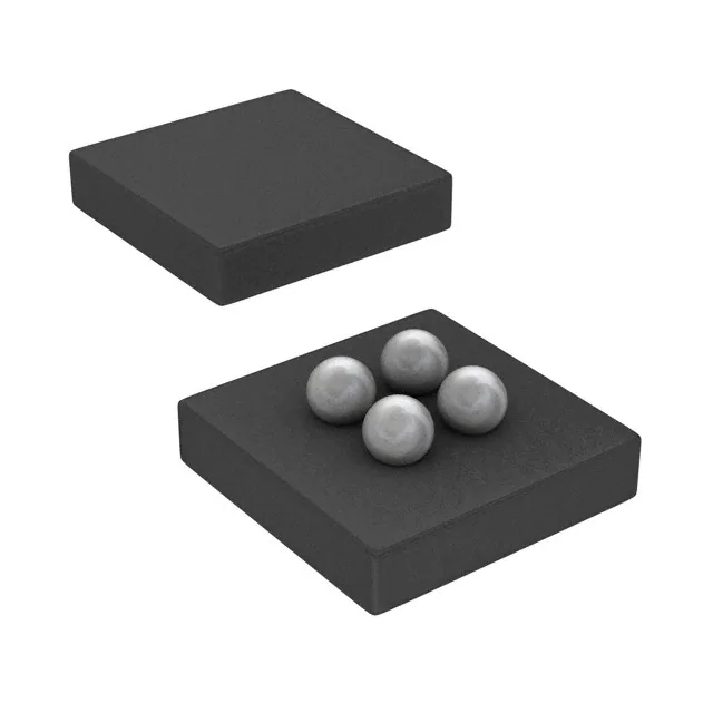
- 4-UFBGA, DSBGA
- Datasheet:
-
 TMP144YFFT.pdf
- Description:
- TMP144 LOW-POWER, DIGITAL TEMPER
- Quantity:
- Payment:

- Shipping:

Inventory:3,537
Please send an inquiry. Send us your inquiry, and we will respond immediately.
Product details
Overview
TMP144YFFT from Texas Instruments is a low-power, 12-bit digital temperature sensor with SMAART Wire™/UART interface in a 4-ball DSBGA (YFF) package. It delivers ±1°C accuracy from –10°C to +100°C, 0.0625°C resolution, and operates from 1.4 V to 3.6 V supply. Its daisy-chain capability supports up to 16 devices on one bus, making it ideal for multi-zone thermal monitoring in space-constrained mobile electronics.
For engineers reviewing the TMP144YFFT datasheet, TMP144YFFT pinout, TMP144YFFT application, or TMP144YFFT equivalent, key selection criteria include its ultra-low 3-μA active current at 0.25 Hz conversion rate, push-pull TX output, MDA (Multiple Device Access) command support, and YFF package's 0.76 mm × 0.96 mm footprint with 625-µm max height.
Technical Context
The TMP144YFFT implements a proprietary SMAART Wire™ interface - UART-compatible, single-wire half-duplex protocol using dedicated RX (input) and TX (push-pull output) pins. It supports daisy-chain topology with automatic address assignment and global MDA commands for simultaneous read/write across up to 16 devices.
Internally, it integrates a thermal BJT sensor, 12-bit ADC, register bank, and configurable functional modes including Continuous Conversion (CR[1:0]-programmable period), One-Shot (26 ms typical conversion), Shutdown (0.6 μA), and Extended Temperature Mode (13-bit output, up to 255.9°C range).
Key Specifications
| Parameter | Value and Actual Design Meaning |
|---|---|
| Resolution | 12-bit (0.0625°C LSB); configurable to 13-bit in Extended Temperature Mode |
| Accuracy | ±1.0°C max over –10°C to +100°C; ±2.0°C max over full –40°C to +125°C range |
| Supply Range | 1.4 V to 3.6 V - enables direct integration with 1.8 V and 3.3 V logic domains |
| Active Current | 3 μA at 0.25 Hz conversion rate - minimizes system-level power budget impact |
| Shutdown Current | 0.6 μA - preserves battery life during idle periods in portable devices |
| Interface | SMAART Wire™/UART (8N1, 4.8–114 kbps) with built-in 28-ms timeout recovery |
| Conversion Time | 26 ms typical one-shot conversion - supports >30 conversions/sec in burst mode |
Pinout & Package
Package: 4-ball DSBGA (YFF), 0.76 mm × 0.96 mm, maximum height 625 µm - optimized for placement under heat-dissipating components to improve thermal response and accuracy.
| Pin/Terminal | Circuit Role | Design Meaning |
|---|---|---|
| V+ | Power supply input | Accepts 1.4–3.6 V; includes internal POR threshold at 0.9 V |
| GND | Ground reference | Return path for analog/digital circuitry and thermal sensing element |
| RX | Serial data input | High-impedance CMOS input (VIH = 0.7×V+, VIL = 0.3×V+); receives calibration byte and commands |
| TX | Serial data output | Push-pull digital output (VOH ≥ V+–0.4 V, VOL ≤ 0.4 V @ 1 mA); drives bus in daisy-chain and interrupt modes |
Key Features
| Feature | Design Value |
|---|---|
| Daisy-chain topology | Up to 16 TMP144YFFT devices share two wires (RX/TX), reducing PCB routing complexity and I/O count |
| Multiple Device Access (MDA) | Global read/write commands eliminate per-device polling - cuts bus traffic by up to 94% in 16-device systems |
| Configurable conversion rate | Four programmable rates (0.125 s to 4 s) via CR[1:0] bits - balances responsiveness vs. power in thermal management loops |
| Temperature alert & interrupt | Programmable high/low limits with latchable flags and bus-hold interrupt (logic-low assertion) - enables autonomous thermal event detection |
| Extended Temperature Mode | 13-bit output format (ETM bit) extends measurable range to 255.9°C - supports high-temp industrial and automotive subsystems |
Applications
| Smartphone Thermal Management | LED Backlight Thermal Compensation |
|---|---|
|
Use Scenario: Real-time die temperature monitoring of AP/SoC and PMIC in compact smartphone PCBs with limited board area. IC Role / Device Role / Timing Role: Primary temperature sensor feeding thermal throttling firmware; provides 0.0625°C resolution readings every 0.25 s in Continuous Mode. Use Value: Enables precise thermal margining - prevents performance throttling until critical junction temperatures are reached, extending user experience duration. |
Use Scenario: Closed-loop dimming control of high-brightness LED arrays in tablets and HDTVs based on local heatsink temperature. IC Role / Device Role / Timing Role: Local thermal feedback node placed adjacent to LED driver IC; operates in One-Shot mode triggered by backlight enable signal. Use Value: Compensates for LED forward-voltage drift with temperature - maintains consistent luminance and color point without external calibration. |
| Enterprise Server DIMM Slot Monitoring | Medical Wearable Skin-Temperature Sensing |
|
Use Scenario: Per-DIMM temperature profiling in dense 1U server chassis where airflow is restricted and hotspots develop unpredictably. IC Role / Device Role / Timing Role: Distributed sensor node on memory module PCB; configured in daisy-chain with 8–12 units per channel for synchronized reads. Use Value: Detects localized overheating before ECC errors occur - triggers dynamic memory frequency scaling or fan ramp-up before thermal shutdown. |
Use Scenario: Direct skin-contact temperature measurement in clinical-grade wearable patches requiring sub-degree accuracy and ultra-low power. IC Role / Device Role / Timing Role: Primary sensing element mounted on flexible substrate; powered from coin cell, wakes every 2 s in Shutdown → One-Shot → Shutdown cycle. Use Value: Achieves 0.6 μA average system current - extends battery life beyond 30 days while maintaining ±0.8°C clinical accuracy per ISO 80601-2-56. |
Equivalent & Alternatives
The following parts are listed as comparable options for similar digital temperature sensor applications.
| Alternative Part | Technical Difference | Application Difference | Selection Advice |
|---|---|---|---|
| MAX31875Y+T | 2-wire I²C interface; ±0.7°C accuracy (–20°C to +100°C); 1.7 V to 3.6 V supply; no daisy-chain or MDA support | Requires dedicated I²C bus lines per device; unsuitable for high-density multi-sensor nodes on shared serial bus | Select when I²C infrastructure exists and <5 sensors per bus are needed; avoid for >8-node thermal networks |
| STTS751-2DFW3F | SMAART Wire™-compatible but non-TI implementation; ±1.5°C accuracy over –40°C to +125°C; 1.7 V to 3.6 V; no Extended Temperature Mode | Lacks ETM and MDA features; interrupt behavior differs (open-drain TX); not drop-in compatible in firmware | Use only with custom driver development; verify timing compliance with TI's 28-ms timeout and calibration sequence |
Compared with MAX31875Y+T and STTS751-2DFW3F, the TMP144YFFT uniquely combines daisy-chain scalability, MDA efficiency, and sub-microwatt shutdown - making it the only option supporting 16-node thermal mapping with <10 μA total bus quiescent current.
Availability
TMP144YFFT is available at Aetrix Electronics and suitable for smartphone thermal management, LED backlight compensation, and enterprise server DIMM monitoring requiring stable component supply across high-volume production cycles.
Supply support for TMP144YFFT includes scheduled delivery planning, volume procurement assistance, BOM continuity management, traceable sourcing, and lifecycle availability coordination for OEM customers, industrial embedded developers, connected-device designers, and electronics production programs.
Manufacturer
Texas Instruments is a global semiconductor leader focused on analog, embedded processing, and connectivity technologies, serving industrial, automotive, and consumer markets with high-reliability silicon solutions.
The TMP144 product line delivers ultra-compact, ultra-low-power digital temperature sensing for thermally dense systems - designed specifically to replace discrete NTC thermistors and legacy I²C sensors in space- and power-constrained mobile and computing platforms.
FAQ
What is the package type and dimensions of the TMP144YFFT?
The TMP144YFFT uses a 4-ball wafer chip-scale package (DSBGA) with YFF designation. Its nominal footprint is 0.76 mm × 0.96 mm, and maximum height is 625 µm. This ultra-thin profile allows placement under heat-dissipating components to improve thermal coupling and response time - a key design advantage confirmed in TI's SBOS891C datasheet Figure 5-1 and Table 5-1.
Does the TMP144YFFT support daisy-chaining, and how many devices can be connected?
Yes, the TMP144YFFT supports daisy-chain configuration using its SMAART Wire™/UART interface. Up to 16 TMP144YFFT devices can be serially connected on a single bus with two wires (RX and TX), as explicitly stated in the device description and illustrated in the simplified application diagram of the SBOS891C datasheet. Each device auto-assigns a unique address during initialization.
What is the temperature accuracy specification for the TMP144YFFT across its operating range?
The TMP144YFFT has ±1.0°C maximum accuracy over –10°C to +100°C and ±2.0°C maximum over its full –40°C to +125°C operating range, per Section 6.5 Electrical Characteristics in the SBOS891C datasheet. Accuracy is specified at V+ = 1.4 V to 3.6 V and includes effects of self-heating per footnote (1). The YFF package exhibits typical error of ±0.5°C in the mid-range, as shown in Figure 6-5.
How does the Multiple Device Access (MDA) feature work in the TMP144YFFT?
The MDA feature in the TMP144YFFT allows the host to issue global read/write commands that all connected TMP144YFFT devices respond to simultaneously - eliminating individual addressing overhead. Supported commands include global software reset, global initialization, global clear interrupt, and global read/write. This reduces bus traffic significantly, especially in systems with >8 sensors, and is detailed in Sections 7.3.1 and Table 7-2 of the SBOS891C datasheet.
What are the power consumption modes of the TMP144YFFT, and what current levels do they draw?
The TMP144YFFT offers four operational modes: Active Conversion (44–100 μA typical), Average (3–10 μA at default 4-s period), Standby (2.5–9.5 μA), and Shutdown (0.6–5 μA). These values are measured at V+ = 3.3 V and TA = 25°C, per Section 6.5 of SBOS891C. The 0.6 μA shutdown current enables multi-year battery life in intermittently sampled applications like medical wearables.
TMP144YFFT Specifications
- Product attributes
- Attribute value
- Manufacturer:
- Texas Instruments
- Series:
- -
- Package/Case:
- 4-UFBGA, DSBGA
- Packaging:
- Tape & Reel (TR)
- Product Status:
- Obsolete
- Sensor Type:
- Digital, Local
- Sensing Temperature - Local:
- -40°C ~ 125°C
- Sensing Temperature - Remote:
- -
- Output Type:
- SMAART Wire, UART
- Voltage - Supply:
- 1.4V ~ 3.6V
- Resolution:
- 12 b
- Features:
- Shutdown Mode, One-Shot
- Accuracy - Highest (Lowest):
- ±1°C (±2°C)
- Test Condition:
- -10°C ~ 100°C (-40°C ~ 125°C)
- Operating Temperature:
- -40°C ~ 125°C (TA)
- Mounting Type:
- Surface Mount
- Grade:
- -
- Qualification:
- -
- Supplier Device Package:
- 4-DSBGA
TMP144YFFT FAQ
1.How can I place an order for TMP144YFFT through Aetrix?
Please submit a Request for Quotation (RFQ) for TMP144YFFT on Aetrix. Our sales agent will provide a competitive quotation and guide you through the order confirmation once you accept the terms.
2.Are the price and stock information for TMP144YFFT reliable?
The price and inventory of TMP144YFFT are updated periodically and may fluctuate due to market conditions. Stock and pricing data are typically refreshed every 24 hours. Quotation validity for TMP144YFFT is usually 5 days.
3.What payment methods are accepted for TMP144YFFT?
We accept Wire Transfer, PayPal, Credit Card, Western Union, MoneyGram, and Escrow for TMP144YFFT transactions.
Note: Certain payment methods may incur a processing fee.
4.How is shipping managed for TMP144YFFT?
TMP144YFFT orders can be shipped via leading logistics carriers, including DHL, UPS, FedEx, TNT, or Registered Mail.
Once your TMP144YFFT order is processed, you will receive an email with the shipment details and tracking number.
Note: Tracking information may take up to 24 hours to appear. Express delivery typically takes 3–5 business days.
5.How can I obtain technical support or documentation for TMP144YFFT?
For technical support, including TMP144YFFT datasheets, pinout diagrams, or application guidance, please contact our engineering support team. They can provide detailed documentation and assistance for your TMP144YFFT requirements.
6.How does Aetrix verify that TMP144YFFT is sourced from the original manufacturer or authorized distributors?
All TMP144YFFT products on Aetrix are procured from qualified distributors and authorized channels. Our dedicated quality assurance team conducts strict verification, including traceability checks and, if necessary, third-party testing. This ensures that TMP144YFFT meets industry standards.
7.What is the process for return or replacement of TMP144YFFT?
All TMP144YFFT units undergo pre-shipment inspection (PSI). If there is an issue with TMP144YFFT, returns or replacements are accepted under the following conditions:
1.Quantity discrepancies, incorrect items, or visible external defects (such as breakage or corrosion), acknowledged by Aetrix.
2.The issue is reported within 90 days of delivery.
3.The TMP144YFFT part is unused and in its original packaging.
Return procedure for TMP144YFFT:
1.Submit a request within 90 days.
2.Obtain a Return Material Authorization (RMA) from Aetrix.
TMP144YFFT Tags
-
MCP9700T-E/TT
Microchip Technology
-
MCP9700T-E/LT
Microchip Technology
-
MCP9701T-E/TT
Microchip Technology
-
MCP9701T-E/LT
Microchip Technology

-
TMP235A4DBZR
Texas Instruments
-
MCP9700AT-E/TT
Microchip Technology
-
MCP9700AT-E/LT
Microchip Technology
-
MCP9701AT-E/LT
Microchip Technology
-
MCP9701AT-E/TT
Microchip Technology
,TO-226_straightlead.jpg)
-
LM335Z
STMicroelectronics
-
TMP1075NDRLR
Texas Instruments
-
TMP1075DGKR
Texas Instruments
Tech Hub

A practical engineering guide to 3.3V and 5V logic compatibility, input thresholds, resistor dividers, translator ICs, MOSFET level shifting, I2C pull-ups, timing limits and power-sequencing risks.

The 74HC595 uses push-pull logic outputs, while the TPIC6B595 uses 50 V open-drain DMOS sinks for higher-power loads. This guide compares timing, current limits, 3.3 V interfacing, load wiring, thermal…

The 74HC595 converts serial data into eight stable parallel outputs. This guide covers pin functions, shift and storage timing, OE and MR behavior, drive-current limits, cascading, voltage compatibilit…

A technical comparison of level-sensitive latches and edge-triggered flip-flops, covering timing windows, setup and hold limits, master–slave operation, time borrowing, race-through, HDL inference and…

A D latch stores one bit while Enable controls when data can pass. This reference covers gate-level operation, truth tables, transparency, setup and hold timing, LE versus OE, common ICs and practical …

An SR latch stores one bit through cross-coupled feedback. This engineering reference covers NOR and NAND implementations, truth tables, forbidden-state recovery, gated operation, switch debouncing, fa…

Latch circuits retain one bit through feedback. This technical reference covers SR and D latches, truth tables, transparency, timing limits, latch-versus-flip-flop behavior, applications and common log…

An engineering guide to LED driver operation, constant-current and constant-voltage outputs, linear and switching topologies, dimming, IC selection, calculations, replacement compatibility, and fault c…

Operational amplifier guide covering op amp basics, feedback, ideal vs real op amps, common configurations, buffer circuits, offset, bias current, gain-bandwidth, slew rate, rail-to-rail limits and sel…

Jumper cables guide covering safe connection order, red and black clamp placement, final ground connection, cable gauge, length, clamp quality, copper vs CCA cables, jump starter comparison and battery…


