
 My Inquiry
 My Account


Texas Instruments TMP513AIRSAR
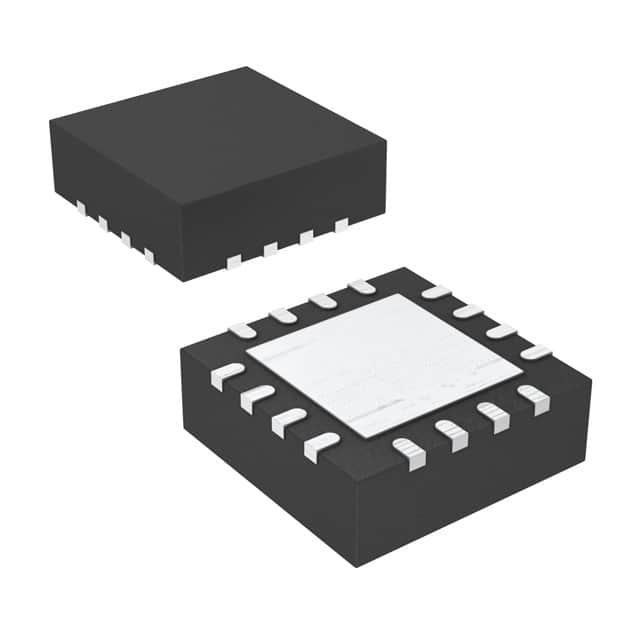
- Part No.:
- TMP513AIRSAR
- Manufacturer:
- Texas Instruments
- Category:
- Thermal Management
- Package:
- 16-VQFN Exposed Pad
- Datasheet:
-
 TMP513AIRSAR.pdf
- Description:
- IC TEMP SNSR TRIPL REMOTE 16QFN
- Quantity:
- Payment:

- Shipping:

Inventory:3,388
Please send an inquiry. Send us your inquiry, and we will respond immediately.
Product details
Overview
TMP513AIRSAR from Texas Instruments is a triple-channel temperature and high-side current/power monitor IC integrating one local diode sensor, three remote diode sensor channels (DXP1/DXN1, DXP2/DXN2, DXP3/DXN3), a 12-bit ADC, series resistance cancellation, and SMBus-compatible two-wire interface. It measures local/remote temperatures (±1°C remote accuracy), bus voltage (0–26 V), current (via shunt), and power (in watts) for real-time system health monitoring in server power rails and FPGA thermal management.
For engineers reviewing the TMP513AIRSAR datasheet, TMP513AIRSAR pinout, TMP513AIRSAR application, or TMP513AIRSAR equivalent, key selection criteria include its triple remote channel support, ±1°C remote diode sensing accuracy across –40°C to +125°C, integrated series resistance cancellation up to 3 kΩ, 12-bit ADC with programmable PGA (÷1 to ÷8), and SMBus alert functionality for over/under-limit watchdogs.
Technical Context
The TMP513AIRSAR implements a dedicated analog front-end with differential shunt voltage inputs (VIN+, VIN–), three independent remote diode excitation channels, and a local temperature sensor-all digitized by a single 12-bit successive-approximation ADC. Its internal subregulator supports three configuration modes (V+ = 3–5.5 V or 4.5–26 V) to enable flexible bus voltage measurement ranges (0–26 V) while maintaining accurate current sensing.
It uses sequential current sourcing (120 μA / 60 μA / 12 μA / 6 μA) per remote channel, n-factor correction (default 1.008), and built-in series resistance cancellation to eliminate PCB trace-induced temperature offset. The SMBus interface supports standard read/write commands, alert masking, and 28-ms timeout protection.
Key Specifications
| Parameter | Value and Actual Design Meaning |
|---|---|
| Remote Temp Accuracy | ±1°C over –40°C to +125°C ambient; enables precise thermal throttling without calibration |
| Local Temp Accuracy | ±0.25°C over +15°C to +85°C; supports die-temperature-based CPU/GPU thermal control |
| ADC Resolution | 12-bit; provides 10 μV LSB for shunt voltage, enabling <1 mA current resolution at 10 mΩ shunt |
| Bus Voltage Range | 0 V to +26 V; covers 12 V, 5 V, 3.3 V, and 24 V industrial rails without external level-shifting |
| Current Sense Range | ±40 mV to ±320 mV full-scale (PGA ÷1 to ÷8); supports wide dynamic range of shunt values and load currents |
| Series Resistance Cancellation | Up to 3 kΩ; removes PCB trace resistance error from remote diode measurements automatically |
| SMBus Compatibility | Full SMBus v1.1 support including Alert response, timeout, and write-read protocols; interoperable with host controllers |
Pinout & Package
Package: SOIC-16 (D package), RoHS-compliant, body size 10.3 mm × 7.5 mm × 2.35 mm, 1.27 mm pitch.
| Pin/Terminal | Circuit Role | Design Meaning |
|---|---|---|
| 1 (Filter C) | Subregulator output filter node | Requires 470 nF capacitor (Config 1/2) or 100 nF (Config 3); stabilizes internal 3.3 V supply for ADC and logic |
| 2 (V+) | Main power input | Accepts +3 V to +26 V; powers internal circuitry and enables bus voltage measurement up to 26 V |
| 3 (VIN+) | High-side shunt positive sense | Connects to shunt resistor's load side; differential input with VIN– for current calculation |
| 4 (VIN–) | High-side shunt negative sense | Connects to shunt resistor's source side; common-mode voltage up to +26 V referenced to GND |
| 5 (SDA) | SMBus data line | Open-drain, requires external pull-up; transmits register reads/writes and alert status |
| 6 (SCL) | SMBus clock line | Open-drain, requires external pull-up; synchronizes all SMBus transactions up to 3.4 MHz |
| 7 (A0) | I²C/SMBus address select | GND/V+/SDA/SCL sets one of four slave addresses (1011100–1011111); enables multi-device bus sharing |
| 8 (DXP1) | Channel 1 remote diode + | Drives excitation current into PNP/NPN transistor base/emitter; paired with DXN1 for ΔVBE measurement |
| 9 (DXN1) | Channel 1 remote diode – | Returns excitation current; differential pair with DXP1 cancels series resistance effects |
| 10 (DXP2) | Channel 2 remote diode + | Independent second remote channel; identical function to DXP1 for dual-processor thermal monitoring |
| 11 (DXN2) | Channel 2 remote diode – | Paired with DXP2; supports separate thermal zones (e.g., CPU + GPU) |
| 12 (DXP3) | Channel 3 remote diode + | Third independent remote channel; enables monitoring of FPGA, VRM, or storage controller junction temp |
| 13 (DXN3) | Channel 3 remote diode – | Completes third remote sensing path; allows full triple-zone thermal mapping |
| 14 (GPIO) | General-purpose I/O | Totem-pole output or digital input; configurable via register; default high-impedance input |
| 15 (ALERT) | SMBus alert output | Open-drain interrupt signal asserted when any programmed limit (temp/current/voltage) is exceeded |
| 16 (GND) | Analog/digital ground reference | Single ground plane required; connects to system GND for accurate shunt and remote measurements |
Key Features
| Feature | Design Value |
|---|---|
| Triple remote diode sensing | Simultaneous monitoring of three independent IC junctions (e.g., CPU, GPU, FPGA) using dedicated DXP/DXN pairs |
| Programmable PGA gain | Four selectable gains (÷1 to ÷8) optimize ADC dynamic range for diverse shunt resistor values (0.5 mΩ to 50 mΩ) |
| Automatic series resistance cancellation | Compensates up to 3 kΩ of PCB trace resistance on remote lines-no firmware or calibration needed |
| n-Factor correction registers | Three independent 8-bit registers (addresses 16h–18h) allow per-channel ideality factor tuning for different transistor types |
| Dual watchdog comparators | Separate upper-over-limit and lower-under-limit thresholds for temperature, voltage, and current registers |
| Subregulator configuration flexibility | Three modes support wide V+ range (3–26 V) while maintaining accurate 0–26 V bus voltage measurement |
Applications
| Server Power Rail Monitoring | FPGA Thermal Management |
|---|---|
Use Scenario: Real-time monitoring of 12 V VRM output voltage, phase current, and power delivery efficiency in dual-socket servers. IC Role / Device Role / Timing Role: High-side current shunt monitor and bus voltage sensor; performs synchronized 12-bit conversions every 130 ms per channel. Use Value: Enables dynamic power capping and predictive failure analysis using correlated voltage/current/temperature trends. | Use Scenario: Junction temperature tracking of Xilinx Kintex UltraScale+ FPGA banks and transceiver tiles during high-throughput data processing. IC Role / Device Role / Timing Role: Triple remote diode sensor interfacing to on-die PNP transistors; applies series resistance cancellation for trace-length robustness. Use Value: Maintains ±1°C remote accuracy across 15 cm PCB traces, preventing thermal runaway during reconfiguration bursts. |
| CPU/GPU Dual-Zone Sensing | Industrial PLC Power Integrity |
Use Scenario: Concurrent die temperature measurement of Intel Xeon CPU and NVIDIA A100 GPU within a single 1U accelerator node. IC Role / Device Role / Timing Role: Local sensor monitors SoC die temp; DXP1/DXN1 and DXP2/DXN2 track discrete GPU junctions. Use Value: Eliminates need for two separate sensors-reduces BOM count and layout area while ensuring synchronized sampling. | Use Scenario: Monitoring 24 V DC input rail, fieldbus module current draw, and ambient cabinet temperature in DIN-rail mounted PLCs. IC Role / Device Role / Timing Role: Bus voltage sensor (VIN+/VIN–), current shunt monitor, and local/remote temperature supervisor. Use Value: Detects brownout conditions, overcurrent faults, and enclosure overheating with single-chip integration and SMBus alert signaling. |
Equivalent & Alternatives
The following parts are listed as comparable options for similar temperature and current monitoring applications.
| Alternative Part | Technical Difference | Application Difference | Selection Advice |
|---|---|---|---|
| TMP512AIRSAT | Dual-channel (2 remote + 1 local) vs. TMP513AIRSAR's triple-channel; same accuracy, PGA, SMBus features; QFN-16 package | Lacks third remote channel; suitable for dual-processor systems but not triple-zone monitoring | Select TMP512AIRSAT only when exactly two remote sensors are required and QFN footprint is preferred |
| INA226AIDGST | Current/voltage/power monitor only-no temperature sensing; 16-bit delta-sigma ADC; higher current accuracy (±0.1%) but no diode interface | No local/remote temperature capability; requires external temperature IC for thermal correlation | Choose INA226AIDGST when precision power metrics dominate and thermal sensing is handled separately |
Compared with TMP512AIRSAT, TMP513AIRSAR adds a third remote channel for expanded thermal visibility without sacrificing accuracy or SMBus compatibility; versus INA226AIDGST, it integrates temperature sensing but trades 16-bit power resolution for unified system monitoring capability.
Availability
TMP513AIRSAR is available at Aetrix Electronics and suitable for server power integrity validation, FPGA thermal profiling, industrial PLC health monitoring, and high-density compute module design requiring stable component supply and long-term lifecycle support.
Supply support for TMP513AIRSAR includes scheduled delivery planning, volume procurement assistance, BOM continuity management, traceable sourcing, and lifecycle availability coordination for OEM customers, industrial embedded developers, connected-device designers, and electronics production programs.
Manufacturer
Texas Instruments is a global semiconductor leader specializing in analog, embedded processing, and high-reliability silicon solutions for industrial, automotive, and communications markets.
The TMP513 product line delivers integrated temperature and power monitoring for complex electronic systems-designed to replace discrete sensor + ADC + MCU combinations with a single SMBus-addressable IC.
FAQ
What is the remote temperature accuracy specification for TMP513AIRSAR over its full operating range?
The TMP513AIRSAR specifies ±1°C remote temperature accuracy over –40°C to +125°C ambient temperature and –40°C to +150°C remote diode temperature, validated across multiple IC manufacturers' transistors without calibration. This accuracy holds under all three subregulator configurations and includes compensation for series resistance up to 3 kΩ. The ±1°C value is confirmed in the Electrical Characteristics table (page 5) of SBOS491A for TEREMOTE at TA = –40°C to +125°C.
How does TMP513AIRSAR handle series resistance in remote diode traces, and what is the maximum supported value?
TMP513AIRSAR implements automatic series resistance cancellation using dual-current excitation and ΔVBE computation, eliminating offset errors caused by PCB trace resistance. It supports up to 3 kΩ total series resistance across both DXP and DXN lines per channel, as verified in Figure 15 and the Series Resistance Cancellation section (page 13). No external components or firmware calibration are required-the feature is always active and transparent to the user.
What are the valid supply voltage ranges for TMP513AIRSAR, and how do they relate to subregulator configuration modes?
TMP513AIRSAR operates from V+ = +3 V to +26 V, but allowable ranges depend on subregulator mode: Configuration 1 requires V+ = 4.5–26 V (bus range 4.5–26 V); Configuration 2 uses V+ = 4.5–26 V (bus range 0–26 V); Configuration 3 restricts V+ to 3–5.5 V (bus range 0–26 V). These modes are set by external connections to Filter C and V+, not registers. All modes maintain ±1% current measurement accuracy and ±1°C remote sensing.
Can TMP513AIRSAR measure both current and power simultaneously with temperature, and how is power calculated?
Yes, TMP513AIRSAR concurrently measures shunt voltage (VIN+–VIN–), bus voltage (VIN– to GND), and temperature. Power is calculated internally as (shunt voltage / shunt resistance) × bus voltage, with results reported directly in watts via the Power Register. The device uses a programmable calibration value and internal digital multiplier-no host MCU computation is needed. Current is reported in amps, voltage in volts, and power in watts, all accessible via SMBus reads.
What is the function of the ALERT pin on TMP513AIRSAR, and how is it configured?
The ALERT pin on TMP513AIRSAR is an open-drain SMBus alert output that asserts low when any enabled limit (temperature upper/lower, voltage upper/lower, or current upper/lower) is violated. It is controlled by the SMBus Alert Mask Register (address 0Ch)-each bit enables/disables alert generation for a specific limit. Default state is disabled; configuration requires writing to the mask register and setting corresponding threshold registers. The pin supports standard SMBus Alert Response Protocol for automatic slave address identification.
TMP513AIRSAR Specifications
- Product attributes
- Attribute value
- Manufacturer:
- Texas Instruments
- Series:
- -
- Package/Case:
- 16-VQFN Exposed Pad
- Packaging:
- Tape & Reel (TR)
- Product Status:
- Active
- Function:
- Temp Monitoring System (Sensor), Watchdog
- Sensor Type:
- Internal and External
- Sensing Temperature:
- -40°C ~ 125°C
- Accuracy:
- ±2.5°C Local(Max), ±5°C Remote(Max)
- Topology:
- ADC, Multiplexer, Register Bank
- Output Type:
- 2-Wire Serial, I2C/SMBUS
- Output Alarm:
- Yes
- Output Fan:
- No
- Voltage - Supply:
- 3V ~ 26V
- Operating Temperature:
- -40°C ~ 125°C
- Grade:
- -
- Qualification:
- -
- Mounting Type:
- Surface Mount
- Supplier Device Package:
- 16-QFN (4x4)
TMP513AIRSAR FAQ
1.How can I place an order for TMP513AIRSAR through Aetrix?
Please submit a Request for Quotation (RFQ) for TMP513AIRSAR on Aetrix. Our sales agent will provide a competitive quotation and guide you through the order confirmation once you accept the terms.
2.Are the price and stock information for TMP513AIRSAR reliable?
The price and inventory of TMP513AIRSAR are updated periodically and may fluctuate due to market conditions. Stock and pricing data are typically refreshed every 24 hours. Quotation validity for TMP513AIRSAR is usually 5 days.
3.What payment methods are accepted for TMP513AIRSAR?
We accept Wire Transfer, PayPal, Credit Card, Western Union, MoneyGram, and Escrow for TMP513AIRSAR transactions.
Note: Certain payment methods may incur a processing fee.
4.How is shipping managed for TMP513AIRSAR?
TMP513AIRSAR orders can be shipped via leading logistics carriers, including DHL, UPS, FedEx, TNT, or Registered Mail.
Once your TMP513AIRSAR order is processed, you will receive an email with the shipment details and tracking number.
Note: Tracking information may take up to 24 hours to appear. Express delivery typically takes 3–5 business days.
5.How can I obtain technical support or documentation for TMP513AIRSAR?
For technical support, including TMP513AIRSAR datasheets, pinout diagrams, or application guidance, please contact our engineering support team. They can provide detailed documentation and assistance for your TMP513AIRSAR requirements.
6.How does Aetrix verify that TMP513AIRSAR is sourced from the original manufacturer or authorized distributors?
All TMP513AIRSAR products on Aetrix are procured from qualified distributors and authorized channels. Our dedicated quality assurance team conducts strict verification, including traceability checks and, if necessary, third-party testing. This ensures that TMP513AIRSAR meets industry standards.
7.What is the process for return or replacement of TMP513AIRSAR?
All TMP513AIRSAR units undergo pre-shipment inspection (PSI). If there is an issue with TMP513AIRSAR, returns or replacements are accepted under the following conditions:
1.Quantity discrepancies, incorrect items, or visible external defects (such as breakage or corrosion), acknowledged by Aetrix.
2.The issue is reported within 90 days of delivery.
3.The TMP513AIRSAR part is unused and in its original packaging.
Return procedure for TMP513AIRSAR:
1.Submit a request within 90 days.
2.Obtain a Return Material Authorization (RMA) from Aetrix.
TMP513AIRSAR Tags

-
EMC2101-ACZL-TR
Microchip Technology

-
MCP9844T-BE/MNY
Microchip Technology
-
EMC2101-R-ACZL-TR
Microchip Technology
-
MCP98244T-BE/MNY
Microchip Technology

-
TC670ECHTR
Microchip Technology

-
SE98ATP,547
NXP Semiconductors
-
AMC6821SDBQR
Texas Instruments

-
MAX6604AATA+T
Analog Devices Inc./Maxim Integrated
-
ADT7475ARQZ-REEL
onsemi
-
MAX6643LBBAEE+
Analog Devices Inc./Maxim Integrated
-
MAX6684ESA+T
Analog Devices Inc./Maxim Integrated
-
MAX6639AEE+
Analog Devices Inc./Maxim Integrated
Tech Hub

A practical engineering guide to 3.3V and 5V logic compatibility, input thresholds, resistor dividers, translator ICs, MOSFET level shifting, I2C pull-ups, timing limits and power-sequencing risks.

The 74HC595 uses push-pull logic outputs, while the TPIC6B595 uses 50 V open-drain DMOS sinks for higher-power loads. This guide compares timing, current limits, 3.3 V interfacing, load wiring, thermal…

The 74HC595 converts serial data into eight stable parallel outputs. This guide covers pin functions, shift and storage timing, OE and MR behavior, drive-current limits, cascading, voltage compatibilit…

A technical comparison of level-sensitive latches and edge-triggered flip-flops, covering timing windows, setup and hold limits, master–slave operation, time borrowing, race-through, HDL inference and…

A D latch stores one bit while Enable controls when data can pass. This reference covers gate-level operation, truth tables, transparency, setup and hold timing, LE versus OE, common ICs and practical …

An SR latch stores one bit through cross-coupled feedback. This engineering reference covers NOR and NAND implementations, truth tables, forbidden-state recovery, gated operation, switch debouncing, fa…

Latch circuits retain one bit through feedback. This technical reference covers SR and D latches, truth tables, transparency, timing limits, latch-versus-flip-flop behavior, applications and common log…

An engineering guide to LED driver operation, constant-current and constant-voltage outputs, linear and switching topologies, dimming, IC selection, calculations, replacement compatibility, and fault c…

Operational amplifier guide covering op amp basics, feedback, ideal vs real op amps, common configurations, buffer circuits, offset, bias current, gain-bandwidth, slew rate, rail-to-rail limits and sel…

Jumper cables guide covering safe connection order, red and black clamp placement, final ground connection, cable gauge, length, clamp quality, copper vs CCA cables, jump starter comparison and battery…


