
 My Inquiry
 My Account


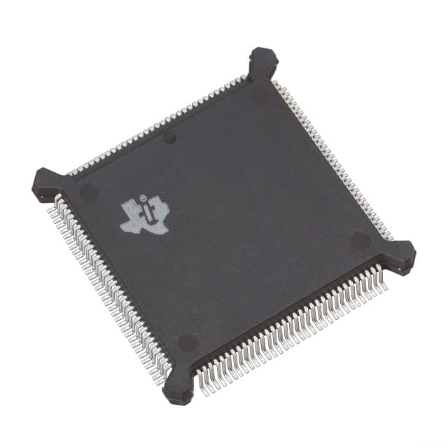
Texas Instruments TMS320C31PQL80
- Part No.:
- TMS320C31PQL80
- Manufacturer:
- Texas Instruments
- Category:
- DSP (Digital Signal Processors)
- Package:
- 132-BQFP Bumpered
- Datasheet:
-
 TMS320C31PQL80.pdf
- Description:
- IC DSP 132-BQFP
- Quantity:
- Payment:

- Shipping:

Inventory:4,081
Please send an inquiry. Send us your inquiry, and we will respond immediately.
Product details
Overview
TMS320C31PQL80 from Texas Instruments is a 32-bit floating-point digital signal processor (DSP) operating at 5 V with 25-ns instruction cycle time, delivering 440 MOPS, 80 MFLOPS, and 40 MIPS. It integrates dual 1K × 32-bit on-chip RAM blocks, one serial port, two 32-bit timers, and a DMA coprocessor - deployed in real-time audio processing, radar baseband computation, and industrial motor control systems.
For engineers reviewing the TMS320C31PQL80 datasheet, TMS320C31PQL80 pinout, TMS320C31PQL80 application, or TMS320C31PQL80 equivalent, key selection considerations include its 132-pin PQ package, 5-V supply requirement, 24-bit address/32-bit data bus, dual-access RAM architecture, and support for zero-overhead loops and parallel ALU/multiplier execution.
Technical Context
The TMS320C31PQL80 implements a hardware-intensive DSP architecture with dedicated ARAUs, extended-precision registers (R0–R7), and interlocked instructions for multiprocessing. Its CPU executes two- and three-operand instructions in single cycles and supports block-repeat and conditional calls/returns.
It features a 0.6 µm EPIC CMOS process, 32-bit instruction word, and memory-mapped peripherals including serial port 0 (CLKX0/CLKR0/FSX0/FSR0/DX0/DR0), timer 0/1 (TCLK0/TCLK1), and interrupt inputs INT0–INT3. Bus control registers configure wait-state generation via STRB and RDY signals.
Key Specifications
| Parameter | Value and Actual Design Meaning |
|---|---|
| Instruction Cycle Time | 25 ns - enables 40 MIPS sustained throughput for tight real-time control loops |
| Floating-Point Performance | 80 MFLOPS - supports high-precision filtering and FFTs in embedded signal chains |
| On-Chip RAM | 2 × 1K × 32-bit dual-access blocks - allows concurrent instruction fetch and data access without pipeline stall |
| Supply Voltage | 5 V (4.75–5.25 V) - requires standard TTL-compatible power rail with decoupling per VDD pin |
| Package | 132-pin plastic quad flat package (PQ) - surface-mount compatible with 0.65 mm pitch and 27.0 × 27.0 mm footprint |
| Operating Temperature | 0°C to 85°C (commercial grade) - validated for non-automotive industrial environments |
| Process Technology | 0.6 µm triple-level-metal CMOS - balances performance, power, and legacy PCB compatibility |
Pinout & Package
132-pin plastic quad flat package (PQ), 27.0 × 27.0 mm body, 0.65 mm lead pitch, JEDEC MS-026 compliant. Thermal pad not present; no exposed die attach pad.
| Pin/Terminal | Circuit Role | Design Meaning |
|---|---|---|
| D31–D0 | 32-bit bidirectional data bus | Transfers instructions/data between CPU and external memory/peripherals; high-impedance during HOLD/SHZ |
| A23–A0 | 24-bit unidirectional address bus | Drives up to 16 MB external memory space; valid during STRB low phase |
| R/W | Read/write control output | High = read, low = write; synchronizes with STRB and H1 timing for bus protocol compliance |
| STRB | External access strobe output | Indicates valid address/data window; used with RDY to insert wait states for slow memory |
| CLKX0 / CLKR0 | Serial port transmit/receive clocks | Independent clock sources for synchronous serial I/O; configurable as input or output |
| XF0 / XF1 | General-purpose I/O flags | Support interlocked instructions for multiprocessor synchronization or external handshake signaling |
Key Features
| Feature | Design Value |
|---|---|
| Parallel ALU + multiplier execution | Single-cycle 32-bit integer or floating-point multiply-accumulate - eliminates pipeline bubbles in FIR/IIR filter kernels |
| Zero-overhead loops | Hardware loop counter with single-cycle branch - reduces instruction overhead in repetitive signal processing tasks |
| Dual 1K × 32-bit RAM blocks | Independent read ports allow simultaneous program fetch and operand load - critical for Viterbi or FFT butterfly operations |
| Two 32-bit timers with TCLK0/TCLK1 | Configurable as free-running, periodic, or pulse-width modulated outputs - directly drive PWM stages or sample clocks |
| Boot-program loader | Supports microcomputer mode loading from serial EEPROM or host processor - enables field firmware updates without JTAG |
Applications
| Audio Signal Processing | Radar Baseband Computation |
|---|---|
Use Scenario: Real-time noise cancellation and echo suppression in professional audio mixing consoles. IC Role / Device Role / Timing Role: Primary DSP executing adaptive LMS algorithms with 128-tap FIR filters at 48 kHz sampling rate. Use Value: 80 MFLOPS enables full-duplex 2-channel processing with <50 µs latency; dual RAM blocks prevent memory contention during coefficient updates. | Use Scenario: Pulse-Doppler signal processing in airborne weather radar systems. IC Role / Device Role / Timing Role: Dedicated baseband processor performing range-Doppler FFTs and CFAR detection on digitized IF samples. Use Value: 440 MOPS sustains 1024-point complex FFT every 250 µs; zero-overhead loops optimize inner-loop execution of matrix rotations. |
| Industrial Motor Control | Communications Modem |
Use Scenario: Field-oriented control (FOC) of 3-phase PMSM motors in CNC spindles. IC Role / Device Role / Timing Role: Real-time executor of Park/Clarke transforms, SVPWM generation, and current-loop PI regulators. Use Value: 40 MIPS delivers sub-5 µs control loop update; TCLK0/TCLK1 timers generate synchronized PWM carrier signals with <100 ns jitter. | Use Scenario: V.34 modem implementation in fax/data terminal equipment. IC Role / Device Role / Timing Role: Host-side DSP handling QAM constellation mapping, trellis coding, and adaptive equalization. Use Value: 32-bit floating-point unit ensures bit-error-rate stability over line SNR down to 22 dB; serial port 0 interfaces directly to analog front-end codec. |
Equivalent & Alternatives
The following parts are listed as comparable options for similar floating-point DSP applications.
| Alternative Part | Technical Difference | Application Difference | Selection Advice |
|---|---|---|---|
| TMS320C32PQL80 | Same C3x core, 80-MFLOPS rating, but includes enhanced boot ROM and improved EMU pin functionality | Preferred for systems requiring secure boot or advanced emulation debugging without external PROM | Select when traceability, debug depth, or ROM-based initialization outweigh cost sensitivity |
| ADSP-21065L | Sharc architecture, 150-MFLOPS, 32-bit fixed/floating, integrated DMA and link ports - higher performance but different ISA and toolchain | Suitable for new designs targeting higher throughput; not drop-in compatible due to memory map and peripheral register differences | Choose for greenfield projects needing >100 MFLOPS and multi-processor linking capability |
Compared with TMS320C32PQL80, the TMS320C31PQL80 lacks on-chip boot ROM and has fewer emulation pins, reducing debug visibility but lowering BOM cost. Against ADSP-21065L, it offers proven legacy toolchain support and lower power, but requires external memory for code storage and lacks native link-port inter-DSP communication.
Availability
TMS320C31PQL80 is available at Aetrix Electronics and suitable for industrial motor control, radar signal processing, audio DSP, and communications modem applications requiring stable component supply across long-lifecycle embedded programs.
Supply support for TMS320C31PQL80 includes scheduled delivery planning, volume procurement assistance, BOM continuity management, traceable sourcing, and lifecycle availability coordination for OEM customers, industrial embedded developers, connected-device designers, and electronics production programs.
Manufacturer
Texas Instruments is a U.S.-based semiconductor company founded in 1930, specializing in analog, embedded processing, and digital signal technologies with global manufacturing and design infrastructure.
The TMS320C3x product line was engineered for high-throughput, low-latency signal processing in resource-constrained embedded systems - emphasizing hardware acceleration of math-intensive operations over general-purpose flexibility.
FAQ
What is the maximum operating frequency supported by the TMS320C31PQL80?
The TMS320C31PQL80 operates with an 80-MHz internal clock derived from a 40-MHz external CLKIN signal (X2/CLKIN). Its 25-ns instruction cycle time corresponds to a sustained 40 MIPS execution rate. The device is rated for 5-V operation and achieves 80 MFLOPS under typical conditions at 25°C ambient temperature. The TMS320C31PQL80 does not support overclocking beyond its specified 40-MHz input clock limit.
Does the TMS320C31PQL80 support JTAG boundary-scan or IEEE 1149.1 debugging?
No, the TMS320C31PQL80 does not implement JTAG boundary-scan. It uses a proprietary four-wire emulation interface (EMU0–EMU3) for real-time debugging, with EMU3 as output and EMU0–EMU2 as inputs. These pins require pull-up resistors and are synchronized to internal clocks; they do not conform to IEEE 1149.1. Debugging relies on TI's XDS510-class emulators and Code Composer Studio v2.x toolchain.
Can the TMS320C31PQL80 execute code directly from external memory without boot-loading?
No, the TMS320C31PQL80 requires boot-loading into internal RAM before execution. It lacks on-chip flash or ROM; all program code must be loaded via microcomputer mode (serial EEPROM/host) or microprocessor mode (parallel bus). Execution begins at address 0x000000 after reset, which maps to internal RAM only after successful boot-load. External memory access is enabled post-boot using STRB/RDY-controlled wait states.
What are the power supply requirements and decoupling recommendations for the TMS320C31PQL80?
The TMS320C31PQL80 requires a clean 5-V ±2.5% supply (4.75–5.25 V) delivered to 20 VDD pins. Each VDD pin must be decoupled with a 0.1-µF ceramic capacitor placed within 5 mm of the pin and connected to the common ground plane. All 25 VSS pins must tie to a solid ground plane; split planes or star grounding is discouraged. Total typical supply current is 450 mA at 80 MHz operation, with peak transient currents managed by local capacitance.
How does the TMS320C31PQL80 handle external memory wait states?
The TMS320C31PQL80 inserts wait states using the RDY input and STRB output in conjunction with programmable bus-control registers. When RDY is low during a memory access, the processor extends the current cycle until RDY goes high. STRB remains active, and address/data remain valid. Wait-state count is controlled by the NOHOLD bit and STRB timing configuration - enabling compatibility with slow SRAM, EPROM, or peripheral devices without external glue logic.
TMS320C31PQL80 Specifications
- Product attributes
- Attribute value
- Manufacturer:
- Texas Instruments
- Series:
- TMS320C3x
- Package/Case:
- 132-BQFP Bumpered
- Packaging:
- Tube
- Product Status:
- Obsolete
- Type:
- Floating Point
- Interface:
- Serial Port
- Clock Rate:
- 80MHz
- Non-Volatile Memory:
- External
- On-Chip RAM:
- 8.25kB
- Voltage - I/O:
- 5.00V
- Voltage - Core:
- 5.00V
- Operating Temperature:
- 0°C ~ 85°C (TC)
- Grade:
- -
- Qualification:
- -
- Mounting Type:
- Surface Mount
- Supplier Device Package:
- 132-BQFP (24.13x24.13)
TMS320C31PQL80 FAQ
1.How can I place an order for TMS320C31PQL80 through Aetrix?
Please submit a Request for Quotation (RFQ) for TMS320C31PQL80 on Aetrix. Our sales agent will provide a competitive quotation and guide you through the order confirmation once you accept the terms.
2.Are the price and stock information for TMS320C31PQL80 reliable?
The price and inventory of TMS320C31PQL80 are updated periodically and may fluctuate due to market conditions. Stock and pricing data are typically refreshed every 24 hours. Quotation validity for TMS320C31PQL80 is usually 5 days.
3.What payment methods are accepted for TMS320C31PQL80?
We accept Wire Transfer, PayPal, Credit Card, Western Union, MoneyGram, and Escrow for TMS320C31PQL80 transactions.
Note: Certain payment methods may incur a processing fee.
4.How is shipping managed for TMS320C31PQL80?
TMS320C31PQL80 orders can be shipped via leading logistics carriers, including DHL, UPS, FedEx, TNT, or Registered Mail.
Once your TMS320C31PQL80 order is processed, you will receive an email with the shipment details and tracking number.
Note: Tracking information may take up to 24 hours to appear. Express delivery typically takes 3–5 business days.
5.How can I obtain technical support or documentation for TMS320C31PQL80?
For technical support, including TMS320C31PQL80 datasheets, pinout diagrams, or application guidance, please contact our engineering support team. They can provide detailed documentation and assistance for your TMS320C31PQL80 requirements.
6.How does Aetrix verify that TMS320C31PQL80 is sourced from the original manufacturer or authorized distributors?
All TMS320C31PQL80 products on Aetrix are procured from qualified distributors and authorized channels. Our dedicated quality assurance team conducts strict verification, including traceability checks and, if necessary, third-party testing. This ensures that TMS320C31PQL80 meets industry standards.
7.What is the process for return or replacement of TMS320C31PQL80?
All TMS320C31PQL80 units undergo pre-shipment inspection (PSI). If there is an issue with TMS320C31PQL80, returns or replacements are accepted under the following conditions:
1.Quantity discrepancies, incorrect items, or visible external defects (such as breakage or corrosion), acknowledged by Aetrix.
2.The issue is reported within 90 days of delivery.
3.The TMS320C31PQL80 part is unused and in its original packaging.
Return procedure for TMS320C31PQL80:
1.Submit a request within 90 days.
2.Obtain a Return Material Authorization (RMA) from Aetrix.
TMS320C31PQL80 Tags
-
TMS320C5535AZAY10
Texas Instruments
-
TMS320VC5501PGF300
Texas Instruments
-
ADSP-BF592KCPZ
Analog Devices Inc.
-
ADAU1463WBCPZ150
Analog Devices Inc.
-
TMS320VC5402PGE100
Texas Instruments
-
ADAU1701JSTZ-RL
Analog Devices Inc.
-
ADAU1701JSTZ
Analog Devices Inc.
-
TMS320VC5502PGF300
Texas Instruments
-
ADAU1462WBCPZ300RL
Analog Devices Inc.
-
ADAU1452KCPZRL
Analog Devices Inc.
-
ADAU1452WBCPZ-RL
Analog Devices Inc.
-
TMS320C6747DZKB3
Texas Instruments
Tech Hub

A practical engineering guide to 3.3V and 5V logic compatibility, input thresholds, resistor dividers, translator ICs, MOSFET level shifting, I2C pull-ups, timing limits and power-sequencing risks.

The 74HC595 uses push-pull logic outputs, while the TPIC6B595 uses 50 V open-drain DMOS sinks for higher-power loads. This guide compares timing, current limits, 3.3 V interfacing, load wiring, thermal…

The 74HC595 converts serial data into eight stable parallel outputs. This guide covers pin functions, shift and storage timing, OE and MR behavior, drive-current limits, cascading, voltage compatibilit…

A technical comparison of level-sensitive latches and edge-triggered flip-flops, covering timing windows, setup and hold limits, master–slave operation, time borrowing, race-through, HDL inference and…

A D latch stores one bit while Enable controls when data can pass. This reference covers gate-level operation, truth tables, transparency, setup and hold timing, LE versus OE, common ICs and practical …

An SR latch stores one bit through cross-coupled feedback. This engineering reference covers NOR and NAND implementations, truth tables, forbidden-state recovery, gated operation, switch debouncing, fa…

Latch circuits retain one bit through feedback. This technical reference covers SR and D latches, truth tables, transparency, timing limits, latch-versus-flip-flop behavior, applications and common log…

An engineering guide to LED driver operation, constant-current and constant-voltage outputs, linear and switching topologies, dimming, IC selection, calculations, replacement compatibility, and fault c…

Operational amplifier guide covering op amp basics, feedback, ideal vs real op amps, common configurations, buffer circuits, offset, bias current, gain-bandwidth, slew rate, rail-to-rail limits and sel…

Jumper cables guide covering safe connection order, red and black clamp placement, final ground connection, cable gauge, length, clamp quality, copper vs CCA cables, jump starter comparison and battery…


