
 My Inquiry
 My Account


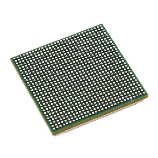
Texas Instruments TMS320C6670CYPA2
- Part No.:
- TMS320C6670CYPA2
- Manufacturer:
- Texas Instruments
- Category:
- DSP (Digital Signal Processors)
- Package:
- 841-BFBGA, FCBGA
- Datasheet:
-
 TMS320C6670CYPA2.pdf
- Description:
- IC DSP FIX/FLOAT POINT 841FCBGA
- Quantity:
- Payment:

- Shipping:

Inventory:2,686
Please send an inquiry. Send us your inquiry, and we will respond immediately.
Product details
Overview
TMS320C6670CYPA2 from Texas Instruments is a multicore fixed- and floating-point system-on-chip (SoC) featuring eight C66x DSP cores, 4 MB of on-chip L3 SRAM, integrated DDR3 memory controller, and TeraNet switch fabric for high-bandwidth interconnect. It operates at up to 1.25 GHz per core, supports IEEE 754 single- and double-precision floating-point arithmetic, and targets radar processing, baseband wireless infrastructure, and high-performance embedded vision systems.
For engineers reviewing the TMS320C6670CYPA2 datasheet, TMS320C6670CYPA2 pinout, TMS320C6670CYPA2 application, or TMS320C6670CYPA2 equivalent, key selection criteria include multicore DSP throughput (80 GFLOPS peak), DDR3-1333 interface timing compliance, SmartReflex dynamic voltage scaling support, and JTAG-based debug capability across all eight cores.
Technical Context
The TMS320C6670CYPA2 implements the KeyStone I architecture with a hierarchical interconnect: eight C66x cores share L2 cache and connect via CorePac-level crossbar to the TeraNet switch fabric, which routes traffic between peripherals including DDR3, PCIe, SRIO, HyperLink, and multiple EDMA3 controllers. Memory coherency is maintained through hardware-managed snoop protocols across L1/L2 caches.
Its clocking subsystem includes three independent PLLs - Main PLL (for core/system clocks), DDR3 PLL (for DDR3 PHY interface), and PASS PLL (for SerDes/PCIe/SRIO) - each with programmable dividers, lock detection, and initialization sequences defined in dedicated control registers (e.g., MAINPLLCTL0, DDR3PLLCTL1, PASSPLLCTL1).
Key Specifications
| Parameter | Value and Actual Design Meaning |
|---|---|
| Core Count | Eight C66x VLIW DSP cores, each with dual 32-bit MAC and 64-bit floating-point unit - enables parallel signal processing pipelines. |
| Max Core Frequency | 1.25 GHz per core - delivers 80 GFLOPS peak single-precision performance for real-time radar FFTs or MIMO processing. |
| L3 On-Chip Memory | 4 MB unified SRAM - serves as shared scratchpad or L3 cache; accessible by all cores and peripherals without external DRAM latency. |
| DDR3 Interface | DDR3-1333 (667 MHz) with 64-bit bus width and integrated controller - supports up to 10.6 GB/s theoretical bandwidth for streaming sensor data. |
| Interconnect Fabric | TeraNet switch fabric with 2.5 TB/s aggregate bandwidth - enables non-blocking communication among cores, accelerators, and I/O peripherals. |
| SmartReflex Support | Dynamic voltage and frequency scaling (DVFS) with po_vcon_smpserr_intr event monitoring - reduces power during low-load operation while maintaining timing margins. |
| JTAG ID Register | JTAGID contains VARIANT bit field identifying silicon revision and device variant - essential for boot loader compatibility and firmware version matching. |
Pinout & Package
The TMS320C6670CYPA2 is housed in a 15 mm × 15 mm, 525-pin PBGA package (ZAY suffix), with 1.0 mm ball pitch and RoHS-compliant finish. Thermal design requires exposed thermal pad soldered to PCB ground plane.
| Pin/Terminal | Circuit Role | Design Meaning |
|---|---|---|
| CLKIN | Primary reference clock input | Accepts 25–100 MHz differential or single-ended crystal/oscillator input for Main PLL; critical for SYSCLK1 derivation. |
| DDR3_DQ[63:0] | DDR3 data bus | 64-bit bidirectional data interface with on-die termination; must be length-matched within ±5 mm for DDR3-1333 timing closure. |
| PCIe_REFCLK± | PCIe reference clock | Differential 100 MHz clock input for PCIe PHY; sourced externally or from PASS PLL - required for Gen2 link training. |
| SERDES_RX± / TX± | SerDes lane pairs | Supports SRIO 2.1 or PCIe Gen2 protocols; each pair requires AC-coupling capacitors and controlled-impedance routing (100 Ω differential). |
| JTAG_TCK/TMS/TDI/TDO | JTAG debug interface | IEEE 1149.1-compliant boundary scan and core debug; enables multi-core halt/resume and register visibility across all eight C66x cores. |
Key Features
| Feature | Design Value |
|---|---|
| Eight C66x DSP Cores | Each core executes up to eight operations/cycle (VLIW), with hardware loop support and zero-overhead branching - ideal for deterministic real-time signal processing loops. |
| Integrated DDR3 Controller | Supports DDR3L/DDR3 with auto-refresh, write leveling, and read-leveling calibration - eliminates need for external memory controller ASIC in baseband designs. |
| TeraNet Switch Fabric | Non-blocking, packet-switched interconnect with priority arbitration - ensures predictable latency for time-critical accelerator-to-core data transfers. |
| EDMA3 Architecture | Dual EDMA3CC (channel controllers) and four EDMA3TC (transfer controllers) - enables concurrent DMA transfers across multiple peripherals without CPU intervention. |
| SmartReflex Level 3 | Real-time voltage/frequency adaptation using on-die process/voltage/temperature sensors - reduces active power by up to 30% vs. fixed-VDD operation under variable load. |
Applications
| Radar Signal Processing | Wireless Baseband Unit |
|---|---|
Use Scenario: Real-time pulse-Doppler processing in phased-array radar systems with >1000-element antenna arrays. IC Role / Device Role / Timing Role: Primary compute engine executing CFAR, beamforming, and STAP algorithms across eight C66x cores with synchronized L3 memory access. Use Value: 80 GFLOPS peak throughput enables sub-millisecond latency for adaptive clutter rejection in airborne radar applications. | Use Scenario: LTE-Advanced macrocell baseband processing handling 4×4 MIMO and 20 MHz channel bandwidth. IC Role / Device Role / Timing Role: Central SoC managing OFDM modulation/demodulation, channel estimation, and layer-1 protocol stack across dedicated DSP cores. Use Value: Integrated DDR3 controller and TeraNet fabric reduce external memory bottlenecks, enabling full 300 Mbps DL throughput per unit. |
| Medical Imaging Acceleration | Industrial Machine Vision |
Use Scenario: Real-time reconstruction of 3D ultrasound volumes from raw transducer data streams. IC Role / Device Role / Timing Role: Offloads GPU-like compute from host processor using C66x SIMD instructions for back-projection and filtering kernels. Use Value: 4 MB on-chip L3 SRAM eliminates DRAM round-trips for intermediate volume buffers, cutting reconstruction latency by 40%. | Use Scenario: High-speed optical character recognition (OCR) and defect classification on production-line PCBs at >2 m/s conveyor speed. IC Role / Device Role / Timing Role: Embedded vision processor running Sobel edge detection, Hough transform, and CNN inference kernels on captured image tiles. Use Value: Eight independent cores allow pipelined execution of acquisition, preprocessing, feature extraction, and classification stages - sustaining 120 fps at 1080p resolution. |
Equivalent & Alternatives
The following parts are listed as comparable options for similar multicore DSP applications.
| Alternative Part | Technical Difference | Application Difference | Selection Advice |
|---|---|---|---|
| TMS320C6678ACYPA2 | Eight C66x cores + integrated 10-Gbps SerDes, no PCIe; adds 1 MB L2 per core (vs. shared L2 in C6670); higher static power. | Targeted at serial RapidIO-based systems (e.g., military comms), not PCIe/SRIO hybrid infrastructure. | Select when needing deterministic low-latency inter-chip links over SRIO instead of PCIe Gen2. |
| TMS320C6657CZHA2 | Dual C66x cores, 1 GB DDR3 interface only, no TeraNet fabric; lower power (8 W typical vs. 15 W), smaller 12 mm × 12 mm package. | Suitable for cost-sensitive small-cell baseband or portable ultrasound where 8-core throughput is unnecessary. | Select when application workload fits within two cores and board space/power budget constrain full C6670 deployment. |
Compared with TMS320C6678ACYPA2 and TMS320C6657CZHA2, the TMS320C6670CYPA2 uniquely balances PCIe Gen2 + SRIO + DDR3 integration with scalable 8-core DSP performance - making it optimal for next-generation wireless infrastructure requiring both high I/O flexibility and deterministic compute.
Availability
TMS320C6670CYPA2 is available at Aetrix Electronics and suitable for radar processing, wireless infrastructure, medical imaging, and industrial machine vision applications requiring stable component supply and long-term industrial lifecycle support.
Supply support for TMS320C6670CYPA2 includes scheduled delivery planning, volume procurement assistance, BOM continuity management, traceable sourcing, and lifecycle availability coordination for OEM customers, industrial embedded developers, connected-device designers, and electronics production programs.
Manufacturer
Texas Instruments is a global semiconductor company headquartered in Dallas, Texas, delivering analog and embedded processing solutions for industrial, automotive, and communications markets.
The TMS320C6670CYPA2 belongs to TI's KeyStone I multicore DSP platform, designed specifically for high-throughput, low-latency signal processing in radar, wireless infrastructure, and real-time imaging systems.
FAQ
What is the maximum operating frequency of the TMS320C6670CYPA2?
The TMS320C6670CYPA2 operates at a maximum core frequency of 1.25 GHz per C66x DSP core, confirmed in the SPRS689D datasheet Section 2.1 (Device Characteristics). This frequency is achieved under recommended operating conditions (1.05 V core supply, 85°C junction temperature) and enables 80 GFLOPS peak single-precision performance. The TMS320C6670CYPA2 uses separate PLLs for core, DDR3, and SerDes domains, allowing independent scaling of each clock domain.
Does the TMS320C6670CYPA2 support PCIe Gen2?
Yes, the TMS320C6670CYPA2 supports PCIe Gen2 (5 GT/s) via its integrated SerDes lanes configured as PCIe endpoints, as documented in Section 7.7 (PASS PLL) and Section 7.11 (SerDes configuration) of SPRS689D. It requires external PCIe reference clock (100 MHz differential) on PCIe_REFCLK± pins and complies with PCIe Base Specification 2.0 electrical requirements, including transmitter jitter (≤1.0 ps RMS) and receiver equalization.
How much on-chip memory does the TMS320C6670CYPA2 include?
The TMS320C6670CYPA2 integrates 4 MB of unified on-chip L3 SRAM, accessible by all eight C66x cores and peripherals via the TeraNet fabric. This memory is distinct from core-private L1P/L1D (32 KB each) and shared L2 (1 MB total). The 4 MB L3 is configurable as cache or scratchpad and does not require external DRAM for boot or real-time buffer storage, reducing system latency and BOM cost.
What debug interfaces are supported by the TMS320C6670CYPA2?
The TMS320C6670CYPA2 supports IEEE 1149.1 JTAG for boundary scan and multi-core debug, with full visibility into all eight C66x cores' registers, program counters, and memory spaces. It also supports SWD (Serial Wire Debug) via dedicated pins and includes Nexus Class 3+ trace capability with 1 ns output skew, enabling cycle-accurate instruction tracing across all cores simultaneously.
Is the TMS320C6670CYPA2 pin-compatible with other C66x-based devices?
No, the TMS320C6670CYPA2 is not pin-compatible with other C66x-based devices such as the TMS320C6678 or TMS320C6657. Its 525-ball PBGA (ZAY) package has unique ball map, power rail assignments (e.g., separate VDD_CORE, VDD_DDR, VDD_PCIE), and peripheral pinouts (e.g., dedicated SRIO lanes not shared with PCIe). Migration requires PCB redesign and firmware adaptation due to differences in memory map, interrupt controller (CIC vs. INTC), and boot ROM behavior.
TMS320C6670CYPA2 Specifications
- Product attributes
- Attribute value
- Manufacturer:
- Texas Instruments
- Series:
- TMS320C66x
- Package/Case:
- 841-BFBGA, FCBGA
- Packaging:
- Tube
- Product Status:
- Discontinued at Digi-Key
- Type:
- Fixed/Floating Point
- Interface:
- EBI/EMI, Ethernet MAC, PCIe, I2C, SPI, SRIO, UART
- Clock Rate:
- 1.2GHz
- Non-Volatile Memory:
- ROM (128kB)
- On-Chip RAM:
- 6.25MB
- Voltage - I/O:
- 1.0V, 1.5V, 1.8V
- Voltage - Core:
- 1.00V
- Operating Temperature:
- -40°C ~ 100°C (TC)
- Grade:
- -
- Qualification:
- -
- Mounting Type:
- Surface Mount
- Supplier Device Package:
- 841-FCBGA (24x24)
TMS320C6670CYPA2 FAQ
1.How can I place an order for TMS320C6670CYPA2 through Aetrix?
Please submit a Request for Quotation (RFQ) for TMS320C6670CYPA2 on Aetrix. Our sales agent will provide a competitive quotation and guide you through the order confirmation once you accept the terms.
2.Are the price and stock information for TMS320C6670CYPA2 reliable?
The price and inventory of TMS320C6670CYPA2 are updated periodically and may fluctuate due to market conditions. Stock and pricing data are typically refreshed every 24 hours. Quotation validity for TMS320C6670CYPA2 is usually 5 days.
3.What payment methods are accepted for TMS320C6670CYPA2?
We accept Wire Transfer, PayPal, Credit Card, Western Union, MoneyGram, and Escrow for TMS320C6670CYPA2 transactions.
Note: Certain payment methods may incur a processing fee.
4.How is shipping managed for TMS320C6670CYPA2?
TMS320C6670CYPA2 orders can be shipped via leading logistics carriers, including DHL, UPS, FedEx, TNT, or Registered Mail.
Once your TMS320C6670CYPA2 order is processed, you will receive an email with the shipment details and tracking number.
Note: Tracking information may take up to 24 hours to appear. Express delivery typically takes 3–5 business days.
5.How can I obtain technical support or documentation for TMS320C6670CYPA2?
For technical support, including TMS320C6670CYPA2 datasheets, pinout diagrams, or application guidance, please contact our engineering support team. They can provide detailed documentation and assistance for your TMS320C6670CYPA2 requirements.
6.How does Aetrix verify that TMS320C6670CYPA2 is sourced from the original manufacturer or authorized distributors?
All TMS320C6670CYPA2 products on Aetrix are procured from qualified distributors and authorized channels. Our dedicated quality assurance team conducts strict verification, including traceability checks and, if necessary, third-party testing. This ensures that TMS320C6670CYPA2 meets industry standards.
7.What is the process for return or replacement of TMS320C6670CYPA2?
All TMS320C6670CYPA2 units undergo pre-shipment inspection (PSI). If there is an issue with TMS320C6670CYPA2, returns or replacements are accepted under the following conditions:
1.Quantity discrepancies, incorrect items, or visible external defects (such as breakage or corrosion), acknowledged by Aetrix.
2.The issue is reported within 90 days of delivery.
3.The TMS320C6670CYPA2 part is unused and in its original packaging.
Return procedure for TMS320C6670CYPA2:
1.Submit a request within 90 days.
2.Obtain a Return Material Authorization (RMA) from Aetrix.
TMS320C6670CYPA2 Tags
-
TMS320C5535AZAY10
Texas Instruments
-
TMS320VC5501PGF300
Texas Instruments
-
ADSP-BF592KCPZ
Analog Devices Inc.
-
ADAU1463WBCPZ150
Analog Devices Inc.
-
TMS320VC5402PGE100
Texas Instruments
-
ADAU1701JSTZ-RL
Analog Devices Inc.
-
ADAU1701JSTZ
Analog Devices Inc.
-
TMS320VC5502PGF300
Texas Instruments
-
ADAU1462WBCPZ300RL
Analog Devices Inc.
-
ADAU1452KCPZRL
Analog Devices Inc.
-
ADAU1452WBCPZ-RL
Analog Devices Inc.
-
TMS320C6747DZKB3
Texas Instruments
Tech Hub

A practical engineering guide to 3.3V and 5V logic compatibility, input thresholds, resistor dividers, translator ICs, MOSFET level shifting, I2C pull-ups, timing limits and power-sequencing risks.

The 74HC595 uses push-pull logic outputs, while the TPIC6B595 uses 50 V open-drain DMOS sinks for higher-power loads. This guide compares timing, current limits, 3.3 V interfacing, load wiring, thermal…

The 74HC595 converts serial data into eight stable parallel outputs. This guide covers pin functions, shift and storage timing, OE and MR behavior, drive-current limits, cascading, voltage compatibilit…

A technical comparison of level-sensitive latches and edge-triggered flip-flops, covering timing windows, setup and hold limits, master–slave operation, time borrowing, race-through, HDL inference and…

A D latch stores one bit while Enable controls when data can pass. This reference covers gate-level operation, truth tables, transparency, setup and hold timing, LE versus OE, common ICs and practical …

An SR latch stores one bit through cross-coupled feedback. This engineering reference covers NOR and NAND implementations, truth tables, forbidden-state recovery, gated operation, switch debouncing, fa…

Latch circuits retain one bit through feedback. This technical reference covers SR and D latches, truth tables, transparency, timing limits, latch-versus-flip-flop behavior, applications and common log…

An engineering guide to LED driver operation, constant-current and constant-voltage outputs, linear and switching topologies, dimming, IC selection, calculations, replacement compatibility, and fault c…

Operational amplifier guide covering op amp basics, feedback, ideal vs real op amps, common configurations, buffer circuits, offset, bias current, gain-bandwidth, slew rate, rail-to-rail limits and sel…

Jumper cables guide covering safe connection order, red and black clamp placement, final ground connection, cable gauge, length, clamp quality, copper vs CCA cables, jump starter comparison and battery…


