
 My Inquiry
 My Account


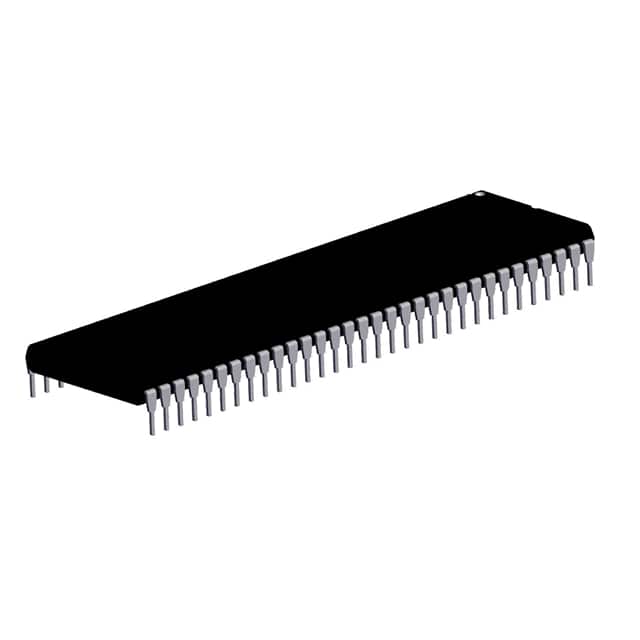
Texas Instruments TMS370C777ANMT
- Part No.:
- TMS370C777ANMT
- Manufacturer:
- Texas Instruments
- Category:
- Microcontrollers
- Package:
- -
- Datasheet:
-
 TMS370C777ANMT.pdf
- Description:
- 8-BIT, OTPROM, TMS370 CPU
- Quantity:
- Payment:

- Shipping:

Inventory:1,588
Please send an inquiry. Send us your inquiry, and we will respond immediately.
Product details
Overview
TMS370C777ANMT from Texas Instruments is an 8-bit OTP EPROM microcontroller with 24 KB program memory, 512-byte RAM, 256-byte data EEPROM, and integrated 8-channel 8-bit ADC1 - designed for automotive and industrial motor control where reprogrammability without windowed packaging is required.
For engineers reviewing the TMS370C777ANMT datasheet, TMS370C777ANMT pinout, TMS370C777ANMT application, or TMS370C777ANMT equivalent, key selection criteria include its 64-pin SDIP package, divide-by-4/divide-by-1 clock options (0.5–5 MHz SYSCLK), STANDBY/HALT low-power modes, and register-to-register architecture supporting 256 general-purpose registers and 14 addressing modes.
Technical Context
The TMS370C777ANMT implements a register-to-register CPU architecture eliminating accumulator bottlenecks, enabling direct arithmetic operations like ADD R24,R47. Its memory map unifies program and data spaces (Von Neumann), with 512-byte RAM (0000h–01FFh), 24 KB EPROM (2000h–7FFFh), and 256-byte EEPROM (1F00h–1FFFh) all accessible via peripheral file addresses 1000h–10FFh.
Peripheral integration includes two 16-bit timers (Timer1 with 8-bit prescaler, Timer2A), a 24-bit watchdog timer, and ADC1 with eight analog inputs (AN0–AN7) mapped to Port E pins. All I/O ports (A–G, D) are software-configurable bidirectional pins, with dedicated functions such as T1PWM, T2AIC2/PWM, and RESET with open-drain output capability for fault indication.
Key Specifications
| Parameter | Value and Actual Design Meaning |
|---|---|
| Core Architecture | 8-bit register-to-register CPU with 256 general-purpose registers and 14 addressing modes - eliminates accumulator dependency for efficient real-time instruction execution. |
| Program Memory | 24 KB one-time-programmable EPROM - supports low-volume production without mask costs; in-circuit programmable via VPP applied to MC pin. |
| Data Memory | 512-byte static RAM + 256-byte data EEPROM - retains critical calibration or configuration data during power loss without external backup. |
| Analog Interface | 8-channel 8-bit ADC1 with dedicated AN0–AN7 inputs - enables direct sensor monitoring (e.g., temperature, voltage) without external signal conditioning. |
| Timing & Control | Two 16-bit general-purpose timers + 24-bit watchdog timer - supports precise event timing, PWM generation, and system-level fault recovery. |
| Power Management | STANDBY and HALT low-power modes - STANDBY maintains oscillator and timer operation; HALT stops all activity while preserving RAM and peripheral state. |
| Supply Voltage | 5 V ±10% (VCC1, VCC2, VCC3) - compatible with standard industrial logic rails; separate VCC/VSS pairs isolate digital I/O and ADC domains. |
Pinout & Package
Package: 64-pin plastic shrink dual-in-line (SDIP), FN/NM suffix - suitable for through-hole prototyping and industrial PCB assembly with verified thermal and mechanical reliability across commercial/industrial temperature ranges.
| Pin/Terminal | Circuit Role | Design Meaning |
|---|---|---|
| A0–A7 | Port A bidirectional I/O | General-purpose digital interface; individually configurable per pin - used for status signaling, control outputs, or input polling. |
| B0–B7 | Port B bidirectional I/O | Primary control port for peripheral enable/disable sequencing and discrete actuator driving in motor control applications. |
| C0–C7 | Port C bidirectional I/O | Secondary I/O bank with flexible remapping - supports multiplexed communication or parallel data bus expansion. |
| D0, D1, D4–D7 | Port D bidirectional I/O | Six-pin port (D2/D3 omitted in 64-pin variant); D3/SYSCLK selectable as system clock input - enables external clock synchronization. |
| E0–E7 / AN0–AN7 | ADC1 analog inputs / Port E inputs | Eight analog channels mapped to Port E; configurable as digital inputs if not used for ADC - simplifies mixed-signal board layout. |
| G0–G5 | Port G bidirectional I/O | General-purpose I/O with no alternate peripheral functions - reserved for user-defined signals or debug interfaces. |
| INT1/NMI, INT2, INT3 | Interrupt inputs | Three prioritized interrupt sources - support real-time response to external events (e.g., encoder edges, fault flags). |
| MC | Mode control | Enables EPROM write-protection override when 12 V applied - required for in-system programming without device removal. |
| RESET | System reset I/O | Bidirectional: input initializes CPU; open-drain output asserts on watchdog or oscillator fault - provides hardware-level system health indication. |
| XTAL1, XTAL2/CLKIN | Oscillator interface | Crystal input/output pair or external clock source - supports internal PLL for divide-by-1 (2–5 MHz) or divide-by-4 (0.5–5 MHz) SYSCLK generation. |
| VCC1, VCC2, VCC3 | Power supply | Separate 5 V supplies for core logic (VCC1), digital I/O (VCC2), and ADC reference (VCC3) - minimizes noise coupling into analog measurements. |
| VSS1, VSS2, VSS3 | Ground reference | Dedicated ground returns for logic (VSS1), I/O (VSS2), and ADC (VSS3) - ensures clean signal integrity in mixed-signal environments. |
Key Features
| Feature | Design Value |
|---|---|
| OTP EPROM with in-circuit programming | Eliminates mask ROM NRE costs while avoiding ceramic window packaging - ideal for low-volume automotive updates and industrial firmware revisions. |
| Register-to-register architecture | Enables single-cycle arithmetic between any two of 256 registers - reduces code size and improves deterministic timing in real-time control loops. |
| Software-configurable I/O ports | All peripheral function pins (e.g., T1PWM, T2AIC2/PWM) can be reassigned as GPIO - maximizes pin utility across product variants without PCB redesign. |
| Dual clock options with PLL | Divide-by-4 (0.5–5 MHz) and divide-by-1 (2–5 MHz) SYSCLK modes - balances power efficiency and performance for varying computational loads. |
| Memory-mapped peripheral file | 256-byte PF space (1000h–10FFh) with frame-based addressing - simplifies driver development and enables consistent register access across all on-chip modules. |
Applications
| Automotive Body Control Module | Industrial Motor Drive Controller |
|---|---|
Use Scenario: Centralized management of door locks, lighting, and window actuators in passenger vehicles. IC Role / Device Role / Timing Role: Main system controller executing real-time CAN message parsing, PWM fan speed regulation, and ADC-based temperature monitoring. Use Value: Integrated 8-bit ADC1 and six I/O ports reduce external component count; OTP EPROM allows field-upgradable firmware for recall compliance. | Use Scenario: Closed-loop speed and position control of BLDC motors in HVAC blowers and conveyor systems. IC Role / Device Role / Timing Role: Real-time execution of commutation logic, current sensing via ADC1, and PWM generation using Timer1/Timer2A modules. Use Value: Register-to-register CPU delivers sub-1 µs instruction latency; STANDBY mode extends battery life in portable drive units. |
| Computer Peripheral Power Manager | Telecom Line Card Supervisor |
Use Scenario: Intelligent power sequencing and thermal monitoring for multi-rail server add-in cards. IC Role / Device Role / Timing Role: System supervisor monitoring 5 V, 3.3 V, and 12 V rails via ADC1 inputs and controlling MOSFET gate drivers via Port B. Use Value: 256-byte EEPROM stores last-fault codes and calibration offsets; watchdog timer ensures fail-safe shutdown on firmware hang. | Use Scenario: Fault detection and alarm reporting in DSLAM line cards operating in telecom central offices. IC Role / Device Role / Timing Role: Standalone monitor of line voltage, temperature, and optical power levels using ADC1, with interrupt-driven event logging. Use Value: 64-pin SDIP package fits legacy telecom PCB footprints; HALT mode reduces standby power to <100 µA for energy-efficient operation. |
Equivalent & Alternatives
The following parts are listed as comparable options for similar 8-bit microcontroller applications.
| Alternative Part | Technical Difference | Application Difference | Selection Advice |
|---|---|---|---|
| TMS370C077ANMT | 24 KB mask-ROM instead of OTP EPROM; identical pinout, peripherals, and memory map - no VPP requirement. | High-volume production only; firmware fixed at manufacture - unsuitable for design iteration or field updates. | Select when firmware is finalized and cost-per-unit optimization is critical; requires mask charge and longer lead time. |
| SE370C777JN | Windowed ceramic package (JN) enabling UV-erasable reprogramming; same OTP EPROM content and peripheral set. | Prototyping and development phase only - UV erasure degrades EPROM cells after ~100 cycles; not rated for production use. | Select for lab validation and breadboard testing; avoid for final BOM due to reliability and lifecycle constraints. |
Compared with TMS370C077ANMT, the TMS370C777ANMT trades mask-ROM permanence for field-programmable flexibility, while SE370C777JN offers greater development agility at the expense of production-grade endurance and packaging robustness.
Availability
TMS370C777ANMT is available at Aetrix Electronics and suitable for automotive body control, industrial motor drives, and telecom line card supervision requiring stable component supply across extended product lifecycles.
Supply support for TMS370C777ANMT includes scheduled delivery planning, volume procurement assistance, BOM continuity management, traceable sourcing, and lifecycle availability coordination for OEM customers, industrial embedded developers, connected-device designers, and electronics production programs.
Manufacturer
Texas Instruments is a global semiconductor leader specializing in analog, embedded processing, and digital signal technologies with over 50 years of microcontroller innovation.
The TMS370Cx7x product line was engineered for cost-effective real-time control in harsh environments - integrating memory, ADC, timers, and low-power modes into a single chip for automotive, industrial, and telecom applications.
FAQ
What is the maximum operating frequency of the TMS370C777ANMT?
The TMS370C777ANMT supports two clock configurations: divide-by-4 mode (0.5–5 MHz SYSCLK) and divide-by-1 mode (2–5 MHz SYSCLK) using its internal PLL. The maximum achievable system clock frequency is 5 MHz in either mode, with timing validated across commercial and industrial temperature ranges per the SPNS034C datasheet revision.
Does the TMS370C777ANMT support in-system programming of its EPROM?
Yes, the TMS370C777ANMT supports in-system programming of its 24 KB OTP EPROM. Programming requires applying 12 V to the MC pin to override write protection, then using the EPCTLL and EPCTLM control registers (P01E and P01C) to manage the 16 KB and 8 KB EPROM arrays respectively - all without removing the TMS370C777ANMT from the target board.
How does the TMS370C777ANMT handle power failure during EEPROM writes?
The TMS370C777ANMT disables data EEPROM writes automatically during reset, low-power mode, or when write protection is active - preventing corruption. Its internal charge pump eliminates need for external VPP, and the DEECTL register (P01A) provides block-level write-enable control, ensuring atomic 32-byte sector updates even under brownout conditions.
Can the ADC1 module of the TMS370C777ANMT operate independently of the CPU?
No, the ADC1 module in the TMS370C777ANMT requires CPU intervention to initiate conversions and read results. It lacks autonomous scan or DMA capability; conversion triggers are software-controlled via ADC1 control registers, and result storage relies on CPU-executed reads from the ADC1 data register - making it suitable for polled or interrupt-driven sampling, not continuous background acquisition.
What are the key differences between the TMS370C777ANMT and the SE370C777JN?
The TMS370C777ANMT uses a plastic SDIP package with one-time-programmable EPROM, while the SE370C777JN uses a windowed ceramic package enabling UV-erasable reprogramming. Both share identical functionality and pinout, but the SE370C777JN is restricted to prototyping due to limited erase endurance (~100 cycles) and lack of automotive/industrial qualification - the TMS370C777ANMT is the production-grade variant.
TMS370C777ANMT Specifications
- Product attributes
- Attribute value
- Manufacturer:
- Texas Instruments
- Package/Case:
- -
- Series:
- TMS370
- Packaging:
- Bulk
- Product Status:
- Active
- Programmable:
- Not Verified
- Core Processor:
- -
- Core Size:
- -
- Speed:
- -
- Connectivity:
- -
- Peripherals:
- -
- Number of I/O:
- -
- Program Memory Size:
- -
- Program Memory Type:
- -
- EEPROM Size:
- -
- RAM Size:
- -
- Voltage - Supply (Vcc/Vdd):
- -
- Data Converters:
- -
- Oscillator Type:
- -
- Operating Temperature:
- -
- Grade:
- -
- Qualification:
- -
- Mounting Type:
- -
- Supplier Device Package:
TMS370C777ANMT FAQ
1.How can I place an order for TMS370C777ANMT through Aetrix?
Please submit a Request for Quotation (RFQ) for TMS370C777ANMT on Aetrix. Our sales agent will provide a competitive quotation and guide you through the order confirmation once you accept the terms.
2.Are the price and stock information for TMS370C777ANMT reliable?
The price and inventory of TMS370C777ANMT are updated periodically and may fluctuate due to market conditions. Stock and pricing data are typically refreshed every 24 hours. Quotation validity for TMS370C777ANMT is usually 5 days.
3.What payment methods are accepted for TMS370C777ANMT?
We accept Wire Transfer, PayPal, Credit Card, Western Union, MoneyGram, and Escrow for TMS370C777ANMT transactions.
Note: Certain payment methods may incur a processing fee.
4.How is shipping managed for TMS370C777ANMT?
TMS370C777ANMT orders can be shipped via leading logistics carriers, including DHL, UPS, FedEx, TNT, or Registered Mail.
Once your TMS370C777ANMT order is processed, you will receive an email with the shipment details and tracking number.
Note: Tracking information may take up to 24 hours to appear. Express delivery typically takes 3–5 business days.
5.How can I obtain technical support or documentation for TMS370C777ANMT?
For technical support, including TMS370C777ANMT datasheets, pinout diagrams, or application guidance, please contact our engineering support team. They can provide detailed documentation and assistance for your TMS370C777ANMT requirements.
6.How does Aetrix verify that TMS370C777ANMT is sourced from the original manufacturer or authorized distributors?
All TMS370C777ANMT products on Aetrix are procured from qualified distributors and authorized channels. Our dedicated quality assurance team conducts strict verification, including traceability checks and, if necessary, third-party testing. This ensures that TMS370C777ANMT meets industry standards.
7.What is the process for return or replacement of TMS370C777ANMT?
All TMS370C777ANMT units undergo pre-shipment inspection (PSI). If there is an issue with TMS370C777ANMT, returns or replacements are accepted under the following conditions:
1.Quantity discrepancies, incorrect items, or visible external defects (such as breakage or corrosion), acknowledged by Aetrix.
2.The issue is reported within 90 days of delivery.
3.The TMS370C777ANMT part is unused and in its original packaging.
Return procedure for TMS370C777ANMT:
1.Submit a request within 90 days.
2.Obtain a Return Material Authorization (RMA) from Aetrix.
TMS370C777ANMT Tags

-
ATTINY4-TSHR
Microchip Technology
-
ATTINY10-TSHR
Microchip Technology
-
ATTINY10-TS8R
Microchip Technology

-
ATTINY202-SSNR
Microchip Technology
-
ATTINY202-SSFR
Microchip Technology
-
ATTINY402-SSNR
Microchip Technology

-
PIC16F15213T-I/MF
Microchip Technology
-
PIC16F15213-E/MF
Microchip Technology

-
PIC10F200T-I/OT
Microchip Technology
-
ATTINY412-SSNR
Microchip Technology
-
PIC10F202T-I/OT
Microchip Technology

-
ATTINY404-SSNR
Microchip Technology
Tech Hub

A practical engineering guide to 3.3V and 5V logic compatibility, input thresholds, resistor dividers, translator ICs, MOSFET level shifting, I2C pull-ups, timing limits and power-sequencing risks.

The 74HC595 uses push-pull logic outputs, while the TPIC6B595 uses 50 V open-drain DMOS sinks for higher-power loads. This guide compares timing, current limits, 3.3 V interfacing, load wiring, thermal…

The 74HC595 converts serial data into eight stable parallel outputs. This guide covers pin functions, shift and storage timing, OE and MR behavior, drive-current limits, cascading, voltage compatibilit…

A technical comparison of level-sensitive latches and edge-triggered flip-flops, covering timing windows, setup and hold limits, master–slave operation, time borrowing, race-through, HDL inference and…

A D latch stores one bit while Enable controls when data can pass. This reference covers gate-level operation, truth tables, transparency, setup and hold timing, LE versus OE, common ICs and practical …

An SR latch stores one bit through cross-coupled feedback. This engineering reference covers NOR and NAND implementations, truth tables, forbidden-state recovery, gated operation, switch debouncing, fa…

Latch circuits retain one bit through feedback. This technical reference covers SR and D latches, truth tables, transparency, timing limits, latch-versus-flip-flop behavior, applications and common log…

An engineering guide to LED driver operation, constant-current and constant-voltage outputs, linear and switching topologies, dimming, IC selection, calculations, replacement compatibility, and fault c…

Operational amplifier guide covering op amp basics, feedback, ideal vs real op amps, common configurations, buffer circuits, offset, bias current, gain-bandwidth, slew rate, rail-to-rail limits and sel…

Jumper cables guide covering safe connection order, red and black clamp placement, final ground connection, cable gauge, length, clamp quality, copper vs CCA cables, jump starter comparison and battery…


