
 My Inquiry
 My Account


Texas Instruments TPA5051RSAT
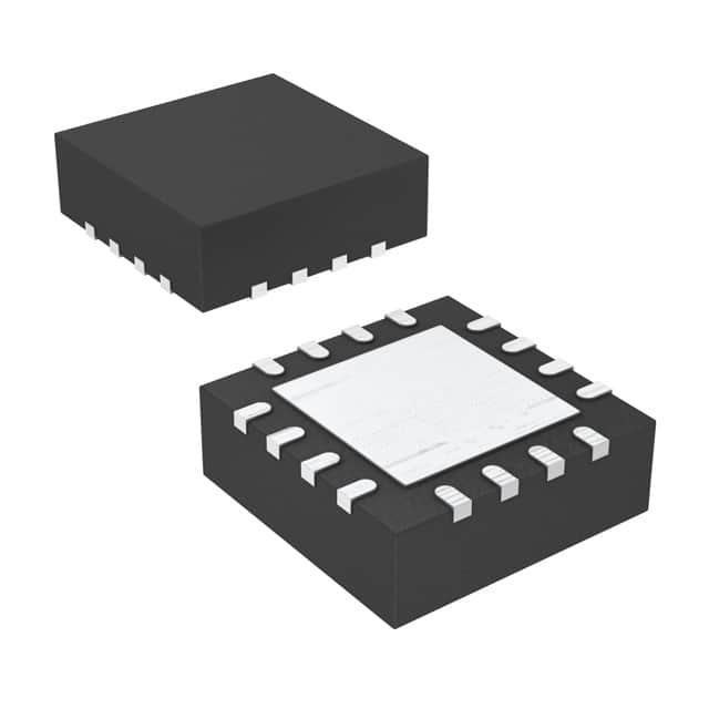
- Part No.:
- TPA5051RSAT
- Manufacturer:
- Texas Instruments
- Category:
- Audio Special Purpose
- Package:
- 16-VQFN Exposed Pad
- Datasheet:
-
 TPA5051RSAT.pdf
- Description:
- IC AUDIO SIGNAL PROCESSOR 16QFN
- Quantity:
- Payment:

- Shipping:

Inventory:2,132
Please send an inquiry. Send us your inquiry, and we will respond immediately.
Product details
Overview
TPA5051RSAT from Texas Instruments is a four-channel digital audio lip-sync delay IC with I²C control, supporting dual serial audio inputs (I²S/right-justified/left-justified, 16–24-bit), independent channel delay up to 85 ms per channel at 48 kHz, and 3.3 V operation with 5 V tolerant I/O. It synchronizes audio to video in flat-panel TVs and home theater systems.
For engineers reviewing the TPA5051RSAT datasheet, TPA5051RSAT pinout, TPA5051RSAT application, or TPA5051RSAT equivalent, this device delivers sample-accurate digital delay for HDMI/ATSC processor interfaces, supports frame-based delay configuration via I²C, and enables series cascading for extended latency-critical for AV synchronization validation and embedded audio subsystem design.
Technical Context
The TPA5051RSAT implements two independent 3-wire synchronous serial audio ports (BCLK/LRCLK/DATA), each feeding a configurable delay memory block with 4095-sample maximum depth (13-bit resolution). Delay values are written via I²C to dedicated upper/lower register pairs per channel (0x02–0x05 for Channel 1; 0x0A–0x0D for Channel 2).
It features dual-mode delay control: sample-based (via left/right delay registers) or frame-based (via Frame Delay register 0x06/0x0E, using programmable frame rate and audio sample rate). All internal clocks derive from incoming BCLK-no external crystal required-and I²C address is set by ADD[2:0] pins (8 possible addresses).
Key Specifications
| Parameter | Value and Actual Design Meaning |
|---|---|
| Delay Range | 0–4095 samples per channel (85.3 ms max at fs = 48 kHz); enables precise A/V sync calibration in TV/video processing pipelines. |
| Audio Input Format | I²S, right-justified, left-justified (16–24-bit); supports standard digital audio streams from ATSC processors, audio codecs, and DSPs. |
| BCLK Support | 32× to 64× fs (fs = 32–192 kHz); accommodates wide bit clock rates without external PLL or clock generation circuitry. |
| I²C Interface | Standard-mode (400 kHz), 7-bit slave address (configurable via ADD0–ADD2), 5 V tolerant; allows direct connection to 3.3 V or 5 V microcontrollers. |
| Supply & I/O | 3.3 V VDD with 5 V tolerant I/O (DATA, LRCLK, BCLK, SCL, SDA, ADDx); simplifies level-shifting in mixed-voltage audio subsystems. |
| Package | 16-pin QFN (4 mm × 4 mm, RSA package); thermal pad required for PCB mounting; supports high-density layout in space-constrained AV modules. |
| Operating Temp | –40°C to +85°C; qualified for consumer electronics and industrial-grade flat-panel display applications. |
Pinout & Package
TPA5051RSAT uses the RSA (QFN) 4 mm × 4 mm, 16-pin surface-mount package with exposed thermal pad (pin 0, soldered to GND plane). All ground pins (5, 14) must be connected to system GND; thermal pad must be soldered for thermal integrity and electrical stability.
| Pin/Terminal | Circuit Role | Design Meaning |
|---|---|---|
| 1 (LRCLK1) | Input | Left/right word clock for Serial Input 1; defines sampling frequency (fs = 32–192 kHz); 5 V tolerant. |
| 2 (DATA1) | Input | Serial audio data input for Channel 1; accepts I²S/right/left-justified formats; 5 V tolerant. |
| 3 (SCL) | Input | I²C clock line; 400 kHz max; 5 V tolerant; requires external pull-up resistor (≤2 kΩ for 5 V bus). |
| 4 (SDA) | I/O | I²C bidirectional data line; 5 V tolerant; requires external pull-up resistor (≤2 kΩ for 5 V bus). |
| 5, 14 (GND) | Power | Ground reference for analog/digital circuits; both pins must connect to system GND plane. |
| 6 (DATA2) | Input | Serial audio data input for Serial Input 2; independent of DATA1; 5 V tolerant. |
| 7 (LRCLK2) | Input | Left/right word clock for Serial Input 2; supports different fs than LRCLK1; 5 V tolerant. |
| 8 (BCLK2) | Input | Bit clock for Serial Input 2; supports different frequency than BCLK1; 5 V tolerant. |
| 9 (DATA_OUT2) | Output | Delayed serial audio output for Channel 2; matches input format; no external buffering required. |
| 10 (ADD0) | Input | I²C address LSB; tied HIGH/LOW to select one of eight slave addresses (1101xxx binary prefix). |
| 11 (ADD1) | Input | I²C address middle bit; used with ADD0/ADD2 for full 3-bit address selection. |
| 12 (ADD2) | Input | I²C address MSB; enables unique I²C addressing when multiple TPA5051RSAT devices are cascaded. |
| 13 (VDD) | Power | 3.3 V supply input; decoupled with single 0.1 µF capacitor to GND; powers all internal logic and delay RAM. |
| 15 (DATA_OUT1) | Output | Delayed serial audio output for Channel 1; synchronized to LRCLK1/BCLK1 timing; 5 V tolerant. |
| 16 (BCLK1) | Input | Bit clock for Serial Input 1; clocks DATA1 on rising edge; 5 V tolerant; determines internal clock domain. |
Key Features
| Feature | Design Value |
|---|---|
| Sample-accurate delay resolution | 1-sample granularity (no interpolation or fractional delay); ensures deterministic lip-sync alignment in broadcast video systems. |
| Dual independent audio paths | Separate BCLK/LRCLK/DATA for each input; allows asynchronous source timing (e.g., HDMI audio + tuner audio) without resampling. |
| Frame-based delay mode | Configurable via register 0x06/0x0E for 50/59.94 Hz video frames and 32–192 kHz audio rates; eliminates manual sample-count calculation. |
| Complete Update register (0x08/0x10) | Atomic commit of delay/stream settings; prevents audio pops during dynamic reconfiguration in live AV systems. |
| Cascadable architecture | Up to 8 devices in series via unique I²C addresses; extends total delay beyond 85 ms while preserving channel independence. |
Applications
| Flat-Panel Television | Home Theater AV Receiver |
|---|---|
|
Use Scenario: Video processing pipeline introduces variable latency (deinterlacing, scaling, motion estimation), causing audio to lead video. IC Role / Device Role / Timing Role: Digital audio delay element placed between audio processor and DAC; compensates for measured video path latency. Use Value: Enables real-time lip-sync correction up to 85 ms per channel using factory-calibrated delay values stored in EEPROM. |
Use Scenario: Rear-channel audio effects (Dolby Digital, DTS) require precise time alignment with front channels after separate decoding paths. IC Role / Device Role / Timing Role: Dual-input delay IC synchronizing rear-channel audio stream to front-channel master clock domain. Use Value: Eliminates phase misalignment and echo artifacts by delaying rear channels to match front-channel group delay. |
| Wireless Speaker System | ATSC Set-Top Box |
|
Use Scenario: Bluetooth/WiFi audio transmission adds unpredictable network jitter, causing audible desync with local video playback. IC Role / Device Role / Timing Role: Front-channel delay buffer accepting wireless audio input and outputting time-aligned I²S to amplifier. Use Value: Provides adaptive buffering and fixed delay tuning to absorb jitter and lock audio to video frame boundaries. |
Use Scenario: ATSC demodulator outputs audio and video with differing processing latencies; broadcast standards mandate ≤40 ms A/V offset. IC Role / Device Role / Timing Role: Lip-sync compliance engine inserted between ATSC audio decoder and HDMI transmitter. Use Value: Guarantees <40 ms A/V deviation across all content types by applying calibrated delay based on detected video frame rate. |
Equivalent & Alternatives
The following parts are listed as comparable options for similar digital audio delay applications.
| Alternative Part | Technical Difference | Application Difference | Selection Advice |
|---|---|---|---|
| TAS5504A | Integrated audio processor with built-in DSP, EQ, and volume control; includes delay but not dedicated lip-sync focus; larger footprint (32-QFN). | Targets full audio post-processing; less optimal for pure delay-only use cases where low latency and minimal BOM are critical. | Select TPA5051RSAT when only precise, low-overhead delay is needed; choose TAS5504A when additional signal conditioning is required. |
| CS8422-CZZ | Dedicated digital audio delay IC (up to 100 ms), but lacks I²C frame-based delay mode and has no dual-input capability. | Suitable for single-stream professional audio routing; does not support independent dual-channel delay or video-frame-aware configuration. | Choose TPA5051RSAT for consumer AV systems requiring HDMI/ATSC integration and frame-rate-aware delay; CS8422-CZZ fits legacy pro-audio infrastructure. |
Compared with TAS5504A and CS8422-CZZ, the TPA5051RSAT offers superior integration of video-frame-aware delay control, dual independent audio paths, and minimal power consumption (3 mA typical), making it uniquely suited for cost-sensitive, space-constrained flat-panel TV and set-top box designs.
Availability
TPA5051RSAT is available at Aetrix Electronics and suitable for flat-panel television manufacturing, home theater AV receiver development, and ATSC set-top box production requiring stable component supply and long-term lifecycle support.
Supply support for TPA5051RSAT includes scheduled delivery planning, volume procurement assistance, BOM continuity management, traceable sourcing, and lifecycle availability coordination for OEM customers, industrial embedded developers, connected-device designers, and electronics production programs.
Manufacturer
Texas Instruments is a global semiconductor leader specializing in analog, embedded processing, and connectivity solutions, with decades of expertise in high-fidelity audio and precision timing products.
The TPA5051RSAT belongs to TI's digital audio interface and synchronization product line, designed specifically for A/V synchronization in consumer electronics where deterministic, low-latency digital delay is essential.
FAQ
What is the maximum audio delay supported by the TPA5051RSAT?
The TPA5051RSAT supports up to 4095 audio samples of delay per channel. At a 48 kHz sampling rate, this equals 85.3 ms (4095 ÷ 48000). The delay is configurable in 1-sample increments via I²C registers 0x02–0x05 (Channel 1) and 0x0A–0x0D (Channel 2), and must be committed using the Complete Update register (0x08 or 0x10) to avoid audio artifacts.
Does the TPA5051RSAT require an external crystal or oscillator?
No, the TPA5051RSAT does not require an external crystal or oscillator. All internal clocks-including those for delay memory and I²C interface-are generated from the incoming BCLK signals (BCLK1 or BCLK2). This eliminates BOM cost and board space for timing components while maintaining sample-accurate delay fidelity.
Can the TPA5051RSAT handle different sampling rates on its two input ports simultaneously?
Yes, the TPA5051RSAT supports independent sampling rates on Serial Input 1 (LRCLK1) and Serial Input 2 (LRCLK2). Each port has its own BCLK and LRCLK inputs, allowing concurrent operation at different fs values (e.g., 44.1 kHz on DATA1 and 48 kHz on DATA2), with independent delay applied to each stream.
How is I²C address configured on the TPA5051RSAT?
The TPA5051RSAT uses three hardware address pins-ADD0 (pin 10), ADD1 (pin 11), and ADD2 (pin 12)-to configure its 7-bit I²C slave address. These pins set the three LSBs of the fixed 4-bit prefix "1101", yielding eight possible addresses (0xD0 to 0xD6 in 8-bit format, R/W bit included). No software address programming is required.
What happens if the Complete Update register is not written after configuring delay registers?
If the Complete Update register (0x08 for Channel 1 or 0x10 for Channel 2) is not written with '1' after modifying delay or stream-type registers, the new settings remain in the configuration shadow registers and are not transferred to the active delay functional block. Audio continues with prior settings-no mute, pop, or glitch occurs, but the intended delay change will not take effect until the update command is issued.
TPA5051RSAT Specifications
- Product attributes
- Attribute value
- Manufacturer:
- Texas Instruments
- Series:
- -
- Package/Case:
- 16-VQFN Exposed Pad
- Packaging:
- Tape & Reel (TR)
- Product Status:
- Active
- Function:
- Audio Signal Processor
- Applications:
- Signal Mixing
- Number of Channels:
- 2
- Interface:
- I2C
- Voltage - Supply:
- 3V ~ 3.6V
- Operating Temperature:
- -40°C ~ 85°C (TA)
- Specifications:
- Delay
- Mounting Type:
- Surface Mount
- Grade:
- -
TPA5051RSAT FAQ
1.How can I place an order for TPA5051RSAT through Aetrix?
Please submit a Request for Quotation (RFQ) for TPA5051RSAT on Aetrix. Our sales agent will provide a competitive quotation and guide you through the order confirmation once you accept the terms.
2.Are the price and stock information for TPA5051RSAT reliable?
The price and inventory of TPA5051RSAT are updated periodically and may fluctuate due to market conditions. Stock and pricing data are typically refreshed every 24 hours. Quotation validity for TPA5051RSAT is usually 5 days.
3.What payment methods are accepted for TPA5051RSAT?
We accept Wire Transfer, PayPal, Credit Card, Western Union, MoneyGram, and Escrow for TPA5051RSAT transactions.
Note: Certain payment methods may incur a processing fee.
4.How is shipping managed for TPA5051RSAT?
TPA5051RSAT orders can be shipped via leading logistics carriers, including DHL, UPS, FedEx, TNT, or Registered Mail.
Once your TPA5051RSAT order is processed, you will receive an email with the shipment details and tracking number.
Note: Tracking information may take up to 24 hours to appear. Express delivery typically takes 3–5 business days.
5.How can I obtain technical support or documentation for TPA5051RSAT?
For technical support, including TPA5051RSAT datasheets, pinout diagrams, or application guidance, please contact our engineering support team. They can provide detailed documentation and assistance for your TPA5051RSAT requirements.
6.How does Aetrix verify that TPA5051RSAT is sourced from the original manufacturer or authorized distributors?
All TPA5051RSAT products on Aetrix are procured from qualified distributors and authorized channels. Our dedicated quality assurance team conducts strict verification, including traceability checks and, if necessary, third-party testing. This ensures that TPA5051RSAT meets industry standards.
7.What is the process for return or replacement of TPA5051RSAT?
All TPA5051RSAT units undergo pre-shipment inspection (PSI). If there is an issue with TPA5051RSAT, returns or replacements are accepted under the following conditions:
1.Quantity discrepancies, incorrect items, or visible external defects (such as breakage or corrosion), acknowledged by Aetrix.
2.The issue is reported within 90 days of delivery.
3.The TPA5051RSAT part is unused and in its original packaging.
Return procedure for TPA5051RSAT:
1.Submit a request within 90 days.
2.Obtain a Return Material Authorization (RMA) from Aetrix.
TPA5051RSAT Tags

-
SA571DR2G
onsemi

-
ADAU7002ACBZ-R7
Analog Devices Inc.

-
DRV135UA/2K5
Texas Instruments

-
DRV134UA/1K
Texas Instruments

-
DRV134PA
Texas Instruments
-
DRV134UA
Texas Instruments
-
DRV135UA
Texas Instruments
-
SA572DR2G
onsemi
-
PGA2311U/1K
Texas Instruments

-
SI8244BB-D-IS1R
Skyworks Solutions Inc.

-
CS8416K-CZZR
Cirrus Logic Inc.

-
SRC4392IPFBR
Texas Instruments
Tech Hub

A practical engineering guide to 3.3V and 5V logic compatibility, input thresholds, resistor dividers, translator ICs, MOSFET level shifting, I2C pull-ups, timing limits and power-sequencing risks.

The 74HC595 uses push-pull logic outputs, while the TPIC6B595 uses 50 V open-drain DMOS sinks for higher-power loads. This guide compares timing, current limits, 3.3 V interfacing, load wiring, thermal…

The 74HC595 converts serial data into eight stable parallel outputs. This guide covers pin functions, shift and storage timing, OE and MR behavior, drive-current limits, cascading, voltage compatibilit…

A technical comparison of level-sensitive latches and edge-triggered flip-flops, covering timing windows, setup and hold limits, master–slave operation, time borrowing, race-through, HDL inference and…

A D latch stores one bit while Enable controls when data can pass. This reference covers gate-level operation, truth tables, transparency, setup and hold timing, LE versus OE, common ICs and practical …

An SR latch stores one bit through cross-coupled feedback. This engineering reference covers NOR and NAND implementations, truth tables, forbidden-state recovery, gated operation, switch debouncing, fa…

Latch circuits retain one bit through feedback. This technical reference covers SR and D latches, truth tables, transparency, timing limits, latch-versus-flip-flop behavior, applications and common log…

An engineering guide to LED driver operation, constant-current and constant-voltage outputs, linear and switching topologies, dimming, IC selection, calculations, replacement compatibility, and fault c…

Operational amplifier guide covering op amp basics, feedback, ideal vs real op amps, common configurations, buffer circuits, offset, bias current, gain-bandwidth, slew rate, rail-to-rail limits and sel…

Jumper cables guide covering safe connection order, red and black clamp placement, final ground connection, cable gauge, length, clamp quality, copper vs CCA cables, jump starter comparison and battery…


