
 My Inquiry
 My Account


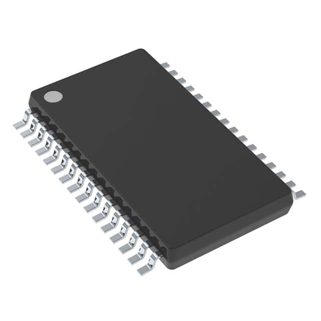
Texas Instruments TPS2206IDAPR
- Part No.:
- TPS2206IDAPR
- Manufacturer:
- Texas Instruments
- Package:
- 32-PowerTSSOP (0.240", 6.10mm Width)
- Datasheet:
-
 TPS2206IDAPR.pdf
- Description:
- IC PWR SWITCH 3:4 32HTSSOP
- Quantity:
- Payment:

- Shipping:

Inventory:3,344
Please send an inquiry. Send us your inquiry, and we will respond immediately.
Product details
Overview
TPS2206IDAPR from Texas Instruments is a dual-slot PC Card power-interface switch IC that integrates MOSFETs, logic control, current limiting, and thermal protection for 3.3-V, 5-V, and 12-V card power distribution. It supports break-before-make switching, features 110-mΩ rDS(on) for 3.3-V VCC outputs, delivers up to 1 A at 3.3 V and 150 mA at 12 V, and enables system reset via dual-active RESET inputs - used in notebook computers and PDAs for compliant PCMCIA power management.
For engineers reviewing the TPS2206IDAPR datasheet, TPS2206IDAPR pinout, TPS2206IDAPR application, or TPS2206IDAPR equivalent, key selection considerations include its 32-pin TSSOP (DAP) package, P2C serial interface compatibility with CardBus controllers, 3.3-V low-voltage mode operation without 5-V bias, integrated overcurrent reporting on OC pin, and dual-slot independent VCC/VPP switching capability.
Technical Context
The TPS2206IDAPR implements a LinBiCMOS-based dual-channel power switch architecture with independent control of two PC Card slots (A and B), each supporting selectable VCC (0/3.3/5 V) and VPP (0/3.3/5/12 V) outputs. Its P2C 3-wire serial interface (DATA/CLOCK/LATCH) enables configuration and status reporting without external address decoding logic.
It incorporates internal charge-pump circuitry to eliminate dependency on external 12-V supply for gate drive - allowing 12-V input to be disabled except during flash programming - and uses dual RESET inputs (active-high on Pin 7, active-low on Pin 14) to synchronize card initialization with host platform reset sequences.
Key Specifications
| Parameter | Value and Actual Design Meaning |
|---|---|
| Supply Inputs | 3.3-V, 5-V, and 12-V independent bias rails; no VDD pin required - bias derived internally from 3.3-V or 5-V input |
| VCC Output Capability | 1 A continuous at 3.3 V; 1 A at 5 V; output voltage regulation maintained per PCMCIA spec (±300 mV at 3.3 V) |
| VPP Output Capability | 150 mA continuous at 12 V; clamp low voltage ≤0.8 V at 10 mA load |
| rDS(on) (3.3-V VCC) | 110 mΩ typical (VI(5V)=5 V); 180 mΩ max (VI(5V)=0) - determines voltage drop under load and thermal dissipation |
| Switching Architecture | Break-before-make timing prevents short-circuit between supply rails; propagation delay ≤25 ms (LATCH↑ to VO(xVCC)) |
| Protection Features | Internal current limiting (no fuses needed), OC pin fault reporting, thermal shutdown at TJ ≥150°C, and short-circuit current limit of 1–2.2 A (VCC), 120–400 mA (VPP) |
| Operating Temperature | −40°C to +85°C ambient; virtual junction temperature rated to +125°C continuous, +150°C absolute max |
Pinout & Package
TPS2206IDAPR is housed in a 32-pin Thin Shrink Small Outline Package (TSSOP), designated DAP, with exposed thermal pad for enhanced heat dissipation. The package measures 7.0 mm × 4.4 mm × 1.2 mm and is RoHS-compliant.
| Pin/Terminal | Circuit Role | Design Meaning |
|---|---|---|
| 1, 2, 32 | 5V Input | Bias and power source for internal logic and 5-V VCC switching; supplies chip when 3.3-V input is inactive |
| 8, 25 | 12V Input | Optional 12-V rail for VPP generation; can be left unconnected when flash programming is not required |
| 10, 11, 12 | AVCC Output | Switched 0/3.3/5 V output for PC Card A VCC; driven by internal MOSFET with 110–180 mΩ rDS(on) |
| 9 | AVPP Output | Switched 0/3.3/5/12 V output for PC Card A VPP; supports flash-memory programming voltage delivery |
| 21, 22, 23 | BVCC Output | Independent switched 0/3.3/5 V output for PC Card B VCC; electrically isolated from AVCC path |
| 24 | BVPP Output | Independent switched 0/3.3/5/12 V output for PC Card B VPP; enables concurrent dual-card flash operations |
| 5, 6 | LATCH Input | Edge-triggered serial data latch signal; initiates update of output states based on DATA/CLOCK sequence |
| 4 | CLOCK Input | Serial interface clock (≤2.5 MHz); synchronizes bit transfer for 9-bit command word (D0–D8) |
| 3 | DATA Input | Serial command data line; carries configuration bits for slot enable/disable, voltage selection, and reset control |
| 7, 14 | RESET Input | Dual RESET inputs: Pin 7 (active-high), Pin 14 (active-low); either may be used to discharge VCC/VPP outputs during system initialization |
| 20 | OC Output | Open-drain overcurrent flag; pulls low when any VCC or VPP output exceeds current limit - enables host microprocessor diagnostics |
| 13 | GND | Power ground reference for all internal circuits and output drivers; connects to PCB ground plane |
| 16, 17, 18 | 3.3V Input | Primary bias source in low-voltage mode; powers internal logic and enables 3.3-V-only operation when 5-V input is absent |
| 3, 19, 26–31 | NC | No internal connection; must remain unconnected on PCB to avoid unintended coupling or ESD paths |
Key Features
| Feature | Design Value |
|---|---|
| Integrated dual-slot power switching | Eliminates discrete MOSFETs, gate drivers, and protection components - reduces BOM count by ≥12 parts per slot |
| P2C 3-wire serial interface | Enables full configuration (voltage selection, enable/disable, reset) using only three GPIO pins - no address lines or parallel bus required |
| 3.3-V low-voltage mode | Operates with 3.3-V input only (VI(5V) = 0), supporting sleep/pager modes where 5-V rail is shut down - quiescent current ≤1 µA in shutdown |
| Charge-pump gate drive | Generates internal high-side gate voltages from 3.3-V or 5-V inputs - removes need for always-on 12-V supply and extends battery life |
| Dual active RESET inputs | Supports both active-high (Pin 7) and active-low (Pin 14) reset signaling - simplifies integration with diverse host controller logic families |
| OC fault reporting pin | Provides real-time overcurrent status to host processor - enables software-initiated recovery instead of hardware fuse replacement |
Applications
| Notebook Computer PC Card Slot | Desktop PCMCIA Expansion Bay |
|---|---|
Use Scenario: Dual-slot PC Card interface in portable notebooks requiring hot-swap support and battery-efficient power sequencing. IC Role / Device Role / Timing Role: Primary power interface IC managing independent VCC/VPP delivery, reset coordination, and overcurrent monitoring for two CardBus-compatible slots. Use Value: Enables 3.3-V-only operation during suspend mode (≤1 µA shutdown current), reduces component count vs. discrete solutions, and meets PCMCIA 3.3-V regulation spec (±300 mV). | Use Scenario: Desktop add-in card bay supporting legacy 5-V and modern 3.3-V PC Cards with shared 12-V flash programming capability. IC Role / Device Role / Timing Role: Dual-channel power switch providing simultaneous, independently controlled VCC and VPP outputs to two physical slots. Use Value: Delivers 1 A at 3.3 V and 150 mA at 12 V per slot while maintaining break-before-make timing - prevents cross-rail shorts during voltage transitions. |
| PDA with CompactFlash Interface | Digital Camera with PCMCIA Modem Card |
Use Scenario: Handheld PDA integrating CompactFlash (CF) storage using PC Card mechanical and electrical interface. IC Role / Device Role / Timing Role: Power management IC supplying regulated 3.3-V VCC to CF card and enabling 12-V VPP only during firmware updates. Use Value: Charge-pump architecture eliminates always-on 12-V rail - extends battery runtime by disabling 12-V supply between flash operations. | Use Scenario: Digital camera with integrated PCMCIA modem for wireless image upload, requiring reliable hot-plug detection and power sequencing. IC Role / Device Role / Timing Role: Dual-slot power controller coordinating reset assertion, VCC ramp-up, and OC fault response for modem card insertion/removal. Use Value: Dual RESET inputs allow synchronization with camera's main SoC reset domain; OC pin enables firmware logging of card faults without hardware intervention. |
Equivalent & Alternatives
The following parts are listed as comparable options for similar PC Card power-switching applications.
| Alternative Part | Technical Difference | Application Difference | Selection Advice |
|---|---|---|---|
| TPS2202IDB | 30-pin SSOP (DB) package; includes VDD pin and APWR_GOOD/BPWR_GOOD status outputs; no 3.3-V low-voltage mode | Requires external 5-V bias; lacks 3.3-V-only operation and charge-pump gate drive - unsuitable for battery-critical sleep modes | Select only if legacy board layout re-use is required and 5-V rail is always available. |
| TPS2206IDBR | Same die and functionality as TPS2206IDAPR but in 30-pin SSOP (DB) package; identical pinout except for package-specific NC assignments | Compatible with existing DB-layout footprints; lower thermal performance than DAP due to smaller thermal pad and no backplane option | Choose for cost-sensitive designs where TSSOP thermal advantages are not required and SSOP assembly infrastructure exists. |
Compared with TPS2202IDB, TPS2206IDAPR adds 3.3-V-only operation and eliminates VDD dependency, while TPS2206IDBR offers footprint compatibility with older SSOP layouts but sacrifices the DAP package's superior thermal dissipation and smaller footprint.
Availability
TPS2206IDAPR is available at Aetrix Electronics and suitable for notebook computers, PDAs, digital cameras, and bar-code scanners requiring stable component supply, long-term industrial lifecycle support, and compliance with PCMCIA power interface standards.
Supply support for TPS2206IDAPR includes scheduled delivery planning, volume procurement assistance, BOM continuity management, traceable sourcing, and lifecycle availability coordination for OEM customers, industrial embedded developers, connected-device designers, and electronics production programs.
Manufacturer
Texas Instruments is a global semiconductor company headquartered in Dallas, Texas, delivering analog, embedded processing, and connectivity products for industrial, automotive, and personal electronics markets.
The TPS2206 series belongs to TI's PC Card interface power management product line, designed specifically to replace discrete MOSFET-based solutions in dual-slot CardBus systems while meeting PCMCIA mechanical, electrical, and timing specifications.
FAQ
What is the function of the OC pin on the TPS2206IDAPR?
The OC (Overcurrent) pin on the TPS2206IDAPR is an open-drain output that asserts low when any VCC or VPP output exceeds its current limit - indicating overcurrent on either slot A or B. This signal allows the host microprocessor to detect faults in real time and initiate diagnostics or user alerts. In the TPS2206IDAPR, OC remains active until the overcurrent condition clears and thermal recovery completes, ensuring robust fault handling without manual fuse replacement.
Does the TPS2206IDAPR require an external 12-V supply to operate?
No, the TPS2206IDAPR does not require an external 12-V supply to operate. Its internal charge pump generates necessary gate-drive voltages from the 3.3-V or 5-V input rails, allowing the 12-V input (Pin 8/25) to be disabled except during flash-memory programming. This feature significantly extends battery life in portable systems. If unused, the 12-V input must remain floating - not grounded - to prevent malfunction of the TPS2206IDAPR.
How does the TPS2206IDAPR support 3.3-V-only system operation?
The TPS2206IDAPR supports true 3.3-V-only operation by deriving all internal bias current from the 3.3-V input pins (16/17/18) when the 5-V input is absent (VI(5V) = 0). In this mode, it delivers 3.3-V VCC to both slots and disables 5-V and 12-V outputs. The TPS2206IDAPR maintains full functionality including RESET, OC reporting, and serial interface control - enabling low-power sleep and pager modes without requiring auxiliary voltage rails.
What is the purpose of the dual RESET inputs on the TPS2206IDAPR?
TPS2206IDAPR provides two independent RESET inputs - Pin 7 (active-high) and Pin 14 (active-low) - to accommodate different host controller logic families without level-shifting circuitry. Either input, when asserted, grounds all VCC and VPP outputs to discharge residual card voltage and ensure clean initialization. The dual configuration eliminates the need for external inverters or pull-up/pull-down resistors, simplifying design integration across diverse platforms using the TPS2206IDAPR.
Can the TPS2206IDAPR replace the TPS2202IDB in an existing design?
The TPS2206IDAPR is backward compatible with the TPS2202IDB in functional behavior but not pin-to-pin due to package (32-pin TSSOP vs. 30-pin SSOP) and pin assignment differences - notably the absence of VDD and APWR_GOOD/BPWR_GOOD pins in the TPS2206IDAPR. To replace TPS2202IDB, PCB layout revision is required. However, the TPS2206IDAPR offers advantages including 3.3-V-only operation, lower quiescent current, and elimination of external 12-V bias - making it suitable for upgraded, power-optimized designs.
TPS2206IDAPR Specifications
- Product attributes
- Attribute value
- Manufacturer:
- Texas Instruments
- Package/Case:
- 32-PowerTSSOP (0.240", 6.10mm Width)
- Series:
- -
- Packaging:
- Tape & Reel (TR)
- Product Status:
- Obsolete
- Switch Type:
- PCMCIA Switch
- Number of Outputs:
- 4
- Ratio - Input:Output:
- 3:4
- Output Configuration:
- High Side
- Output Type:
- -
- Interface:
- Serial
- Voltage - Load:
- 3.3V, 5V, 12V
- Voltage - Supply (Vcc/Vdd):
- Not Required
- Current - Output (Max):
- 1A
- Rds On (Typ):
- 103mOhm
- Input Type:
- -
- Features:
- Status Flag
- Fault Protection:
- Current Limiting (Fixed), Over Temperature
- Operating Temperature:
- -40°C ~ 85°C (TA)
- Grade:
- -
- Qualification:
- -
- Mounting Type:
- Surface Mount
- Supplier Device Package:
- 32-HTSSOP
TPS2206IDAPR FAQ
1.How can I place an order for TPS2206IDAPR through Aetrix?
Please submit a Request for Quotation (RFQ) for TPS2206IDAPR on Aetrix. Our sales agent will provide a competitive quotation and guide you through the order confirmation once you accept the terms.
2.Are the price and stock information for TPS2206IDAPR reliable?
The price and inventory of TPS2206IDAPR are updated periodically and may fluctuate due to market conditions. Stock and pricing data are typically refreshed every 24 hours. Quotation validity for TPS2206IDAPR is usually 5 days.
3.What payment methods are accepted for TPS2206IDAPR?
We accept Wire Transfer, PayPal, Credit Card, Western Union, MoneyGram, and Escrow for TPS2206IDAPR transactions.
Note: Certain payment methods may incur a processing fee.
4.How is shipping managed for TPS2206IDAPR?
TPS2206IDAPR orders can be shipped via leading logistics carriers, including DHL, UPS, FedEx, TNT, or Registered Mail.
Once your TPS2206IDAPR order is processed, you will receive an email with the shipment details and tracking number.
Note: Tracking information may take up to 24 hours to appear. Express delivery typically takes 3–5 business days.
5.How can I obtain technical support or documentation for TPS2206IDAPR?
For technical support, including TPS2206IDAPR datasheets, pinout diagrams, or application guidance, please contact our engineering support team. They can provide detailed documentation and assistance for your TPS2206IDAPR requirements.
6.How does Aetrix verify that TPS2206IDAPR is sourced from the original manufacturer or authorized distributors?
All TPS2206IDAPR products on Aetrix are procured from qualified distributors and authorized channels. Our dedicated quality assurance team conducts strict verification, including traceability checks and, if necessary, third-party testing. This ensures that TPS2206IDAPR meets industry standards.
7.What is the process for return or replacement of TPS2206IDAPR?
All TPS2206IDAPR units undergo pre-shipment inspection (PSI). If there is an issue with TPS2206IDAPR, returns or replacements are accepted under the following conditions:
1.Quantity discrepancies, incorrect items, or visible external defects (such as breakage or corrosion), acknowledged by Aetrix.
2.The issue is reported within 90 days of delivery.
3.The TPS2206IDAPR part is unused and in its original packaging.
Return procedure for TPS2206IDAPR:
1.Submit a request within 90 days.
2.Obtain a Return Material Authorization (RMA) from Aetrix.
TPS2206IDAPR Tags

-
TPS22919DCKR
Texas Instruments

-
MIC2091-1YM5-TR
Microchip Technology

-
MIC2090-1YM5-TR
Microchip Technology

-
TPS22995RZFR
Texas Instruments

-
TPS22975DSGR
Texas Instruments

-
SIP32510DT-T1-GE3
Vishay Siliconix

-
ULN2003D1013TR
STMicroelectronics

-
MIC2005A-1YM5-TR
Microchip Technology

-
MIC2005A-1YM6-TR
Microchip Technology

-
TPS22916BYFPR
Texas Instruments

-
TPS22917DBVR
Texas Instruments

-
ULN2003APWR
Texas Instruments
Tech Hub

A practical engineering guide to 3.3V and 5V logic compatibility, input thresholds, resistor dividers, translator ICs, MOSFET level shifting, I2C pull-ups, timing limits and power-sequencing risks.

The 74HC595 uses push-pull logic outputs, while the TPIC6B595 uses 50 V open-drain DMOS sinks for higher-power loads. This guide compares timing, current limits, 3.3 V interfacing, load wiring, thermal…

The 74HC595 converts serial data into eight stable parallel outputs. This guide covers pin functions, shift and storage timing, OE and MR behavior, drive-current limits, cascading, voltage compatibilit…

A technical comparison of level-sensitive latches and edge-triggered flip-flops, covering timing windows, setup and hold limits, master–slave operation, time borrowing, race-through, HDL inference and…

A D latch stores one bit while Enable controls when data can pass. This reference covers gate-level operation, truth tables, transparency, setup and hold timing, LE versus OE, common ICs and practical …

An SR latch stores one bit through cross-coupled feedback. This engineering reference covers NOR and NAND implementations, truth tables, forbidden-state recovery, gated operation, switch debouncing, fa…

Latch circuits retain one bit through feedback. This technical reference covers SR and D latches, truth tables, transparency, timing limits, latch-versus-flip-flop behavior, applications and common log…

An engineering guide to LED driver operation, constant-current and constant-voltage outputs, linear and switching topologies, dimming, IC selection, calculations, replacement compatibility, and fault c…

Operational amplifier guide covering op amp basics, feedback, ideal vs real op amps, common configurations, buffer circuits, offset, bias current, gain-bandwidth, slew rate, rail-to-rail limits and sel…

Jumper cables guide covering safe connection order, red and black clamp placement, final ground connection, cable gauge, length, clamp quality, copper vs CCA cables, jump starter comparison and battery…


