
 My Inquiry
 My Account


Texas Instruments TPS25810TWRVCRQ1
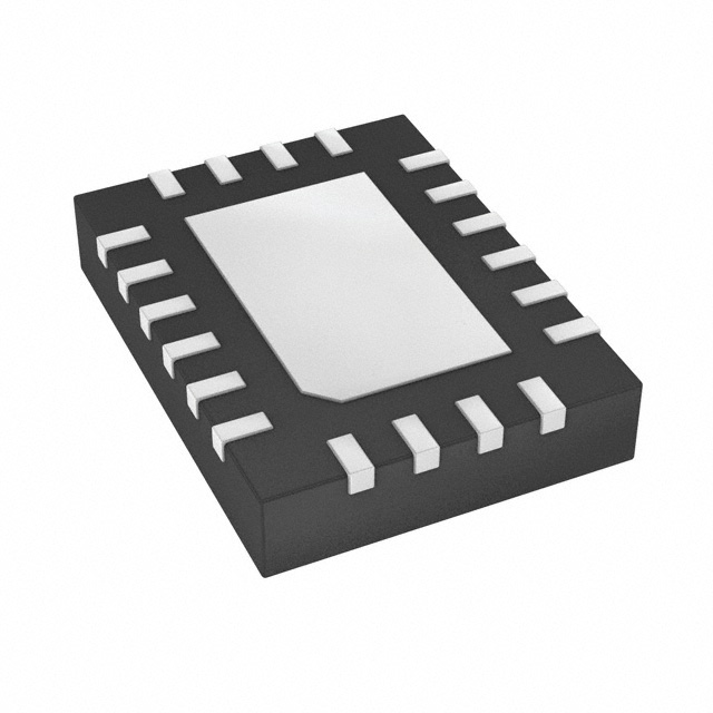
- Part No.:
- TPS25810TWRVCRQ1
- Manufacturer:
- Texas Instruments
- Category:
- Specialized
- Package:
- 20-WFQFN Exposed Pad
- Datasheet:
-
 TPS25810TWRVCRQ1.pdf
- Description:
- IC INTERFACE SPECIALIZED 20WQFN
- Quantity:
- Payment:

- Shipping:

Inventory:1,674
Please send an inquiry. Send us your inquiry, and we will respond immediately.
Product details
Overview
TPS25810TWRVCRQ1 from Texas Instruments is an AEC-Q100 qualified USB Type-C downstream-facing port (DFP) controller with integrated 3-A power switch, CC line monitoring, VCONN generation, and load-detection logic. It operates across 4.5–6.5 V (IN1), supports dual current limits (1.7 A / 3.4 A ±7.1%), features 34-mΩ typical RDS(on), and delivers <0.7 µA quiescent current in unattached state - enabling automotive infotainment and rear-seat charging systems.
For engineers reviewing the TPS25810TWRVCRQ1 datasheet, TPS25810TWRVCRQ1 pinout, TPS25810TWRVCRQ1 application, or TPS25810TWRVCRQ1 equivalent, key selection criteria include its USB Type-C Rev. 1.2 DFP compliance, integrated VBUS/VCONN switching, polarity detection (POL), UFP identification, and LD_DET-based multi-port power arbitration - all in a thermally enhanced 20-pin WQFN (3 mm × 4 mm) package.
Technical Context
The TPS25810TWRVCRQ1 implements a dual-path analog front-end for CC1/CC2 to detect Rd (UFP), Ra (cable/audio), and floating states, enabling role determination, cable orientation resolution, and accessory mode identification. Its internal state machine sequences VBUS application, VCONN enablement, and current-limit selection based on CHG/CHG_HI inputs and real-time CC signaling.
It integrates two independent high-side switches: a 3-A VBUS switch (34-mΩ typ) with programmable ILIM and thermal shutdown at 135°C/155°C, and a 250-mA VCONN switch (365-mΩ typ) with separate current limiting. All open-drain outputs (FAULT, UFP, AUDIO, DEBUG, POL, LD_DET) are internally pulled low on assertion and require external 100-kΩ pull-ups to AUX.
Key Specifications
| Parameter | Value and Actual Design Meaning |
|---|---|
| VBUS Switch RDS(on) | 34 mΩ typ at 25°C - enables low-loss 3-A power delivery with <100 mV drop at full load |
| Current Limit Options | 1.7 A or 3.4 A ±7.1% - matches USB Type-C standard current modes (STD/1.5-A/3-A) |
| Quiescent Current (Unattached) | 0.7 µA typ - minimizes standby power in automotive S4/S5 hibernate states |
| VCONN Switch Capability | 250 mA max, 365-mΩ typ RDS(on) - powers electronically marked cables per USB Type-C spec |
| Load Detect Threshold | 1.95 A nominal rising threshold with 125 mA hysteresis - triggers LD_DET for multi-port power management |
| ESD Rating (CC1/CC2) | ±8 kV contact / ±15 kV air per IEC 61000-4-2 - ensures robustness in automotive connector environments |
| Operating Junction Temp | –40°C to +125°C - qualified for under-hood and infotainment module deployment |
Pinout & Package
TPS25810TWRVCRQ1 is housed in a 20-pin WQFN package (3.00 mm × 4.00 mm) with exposed thermal pad connected internally to GND. The thermal pad must be soldered to the PCB ground plane for reliable thermal performance (RθJB = 13°C/W).
| Pin/Terminal | Circuit Role | Design Meaning |
|---|---|---|
| 1 FAULT | Open-drain fault indicator | Asserts low on overcurrent or overtemperature; requires 100-kΩ pull-up to AUX |
| 2–3 IN1 | VBUS input supply | Dual-pin connection for high-current VBUS input (4.5–6.5 V); feeds main power switch |
| 4 IN2 | VCONN input supply | Accepts 4.5–5.5 V supply for VCONN generation; shorted to IN1 if single-rail used |
| 5 AUX | Auxiliary system rail | Enables power-wake in S4/S5; powers logic when IN1/IN2 are disabled |
| 6 EN | Enable control input | Active-high logic input; device disabled when pulled low or floating (internal weak pull-down) |
| 11 CC1 / 13 CC2 | Configuration channel I/O | Analog bidirectional pins for Rd/Ra detection, polarity resolution, and accessory identification |
| 14–15 OUT | VBUS power switch output | Dual-pin connection to Type-C receptacle VBUS; supports 3-A continuous load |
| 19 UFP | Upstream-facing port indicator | Open-drain output asserting low when valid UFP (Rd termination) is detected on CC lines |
| 20 LD_DET | Load-detect output | Asserts low when VBUS current exceeds 1.95 A - used for inter-port power arbitration |
Key Features
| Feature | Design Value |
|---|---|
| USB Type-C Rev. 1.2 DFP Compliance | Fully implements CC line monitoring, Rd/Ra detection, cable orientation resolution, and current advertisement per spec - no external MCU required |
| Integrated Dual Power Switches | Single-chip solution combines 3-A VBUS switch (34-mΩ) and 250-mA VCONN switch (365-mΩ) - eliminates discrete FETs and gate drivers |
| Multi-Rail Power Architecture | Three independent supplies (IN1/VBUS, IN2/VCONN, AUX/standby) enable flexible power sequencing and low-power hibernation without external LDOs |
| Automotive-Grade Reliability | AEC-Q100 Grade 1 qualification, ±8 kV IEC 61000-4-2 ESD on CC pins, and 155°C thermal shutdown ensure robust operation in harsh vehicle environments |
| Intelligent Port Power Management | LD_DET output enables dynamic current allocation across multiple Type-C ports - prevents simultaneous 3-A sourcing when system power budget is constrained |
Applications
| Automotive Infotainment Head Unit | Rear-Seat USB Charging Hub |
|---|---|
Use Scenario: Integrated USB-C port in center-stack head unit supporting smartphone connectivity and media transfer. IC Role / Device Role / Timing Role: DFP controller managing VBUS application, CC negotiation, and polarity detection for SuperSpeed data routing. Use Value: Eliminates need for separate CC logic IC and power switch; reduces BOM count by 3+ components while ensuring AEC-Q100 compliance. |
Use Scenario: Multi-port charging module in rear console powering tablets, headphones, and accessories. IC Role / Device Role / Timing Role: Load-detect-enabled DFP coordinating power allocation across parallel TPS25810TWRVCRQ1 instances via LD_DET signals. Use Value: Prevents system overcurrent by dynamically disabling non-critical ports when total load exceeds 6 A - avoids fuse blowing or rail collapse. |
| Automotive Diagnostic Interface | USB-C Audio Adapter Detection |
Use Scenario: OBD-II dongle interface using USB-C for firmware updates and real-time CAN diagnostics. IC Role / Device Role / Timing Role: Debug accessory identifier triggering DEBUG output upon Ra+Rd signature detection on CC lines. Use Value: Enables automatic host-mode reconfiguration and secure diagnostic session initiation without manual port selection. |
Use Scenario: In-vehicle entertainment system detecting analog audio adapters for headphone output routing. IC Role / Device Role / Timing Role: Audio accessory detector asserting AUDIO output when Ra termination appears on both CC1 and CC2. Use Value: Allows seamless analog audio passthrough without USB enumeration delay - critical for low-latency cabin audio use cases. |
Equivalent & Alternatives
The following parts are listed as comparable options for similar USB Type-C DFP controller applications.
| Alternative Part | Technical Difference | Application Difference | Selection Advice |
|---|---|---|---|
| TPS65987D | Supports full USB Power Delivery (up to 100 W), includes PD controller, ARM Cortex-M0+, and 4-channel MUX control - significantly higher integration and cost | Required for systems needing variable VBUS (9/15/20 V), sink capability, or DRP functionality - not suitable for fixed 5-V DFP-only designs | Select only if USB PD negotiation, bidirectional power, or embedded policy engine is required; overkill for basic 5-V charging |
| USB3200 | Legacy USB 2.0 BC1.2 charger detector (no CC logic); lacks VCONN, LD_DET, POL, or UFP outputs - discrete solution requiring external switch and level-shifting | Targets cost-sensitive non-Type-C designs with micro-B connectors and basic 500-mA/1.5-A charging - no support for flip-over, audio, or debug accessories | Use only for legacy USB-A/micro-B ports; incompatible with Type-C mechanical or protocol requirements |
Compared with TPS65987D and USB3200, the TPS25810TWRVCRQ1 delivers optimal balance of USB Type-C DFP functionality, automotive qualification, and minimal external component count - making it the most direct fit for fixed 5-V, single-role, AEC-Q100-compliant automotive charging applications.
Availability
TPS25810TWRVCRQ1 is available at Aetrix Electronics and suitable for automotive infotainment systems, rear-seat USB charging hubs, and OBD-II diagnostic interfaces requiring stable component supply, AEC-Q100 compliance, and long-term production continuity.
Supply support for TPS25810TWRVCRQ1 includes scheduled delivery planning, volume procurement assistance, BOM continuity management, traceable sourcing, and lifecycle availability coordination for OEM customers, industrial embedded developers, connected-device designers, and electronics production programs.
Manufacturer
Texas Instruments is a global semiconductor company specializing in analog, embedded processing, and automotive-grade ICs, with leadership in power management and interface solutions.
The TPS25810TWRVCRQ1 belongs to TI's automotive USB Type-C portfolio, designed specifically for AEC-Q100-compliant DFP implementations in infotainment, telematics, and charging systems where reliability, low quiescent current, and CC-line intelligence are critical.
FAQ
What is the primary function of the TPS25810TWRVCRQ1 in a USB Type-C system?
The TPS25810TWRVCRQ1 serves as a dedicated downstream-facing port (DFP) controller with integrated power switches. It monitors CC1/CC2 lines to detect attachments, applies VBUS power, supplies VCONN to electronically marked cables, identifies audio/debug accessories, and asserts UFP/POL/LD_DET signals - all without requiring a host MCU. Its core function is autonomous USB Type-C port control in automotive environments.
Does the TPS25810TWRVCRQ1 support USB Power Delivery (PD) negotiation?
No, the TPS25810TWRVCRQ1 does not support USB Power Delivery (PD) negotiation. It is designed exclusively for fixed 5-V VBUS operation and complies only with USB Type-C Rev. 1.2 DFP requirements. It cannot negotiate voltages above 5 V or handle PD message exchange - for PD capability, TI recommends the TPS65987D or TPS65988.
How does the LD_DET pin function in multi-port systems using TPS25810TWRVCRQ1?
The LD_DET pin on the TPS25810TWRVCRQ1 asserts low when VBUS current exceeds 1.95 A (rising threshold). In multi-port systems, LD_DET outputs from multiple TPS25810TWRVCRQ1 devices are wire-OR'd to disable non-critical ports via their EN pins - ensuring total system current stays within the available power budget. This enables intelligent, hardware-based load sharing without software intervention.
What are the voltage ranges supported by each supply input on the TPS25810TWRVCRQ1?
The TPS25810TWRVCRQ1 supports three independent supplies: IN1 accepts 4.5–6.5 V for VBUS switching; IN2 accepts 4.5–5.5 V for VCONN generation; and AUX accepts 2.9–5.5 V for logic and power-wake operation. Each has distinct UVLO thresholds (IN1: 4.1 V, IN2: 4.1 V, AUX: 2.75 V), allowing flexible rail sequencing and low-power S4/S5 operation from a 3.3-V auxiliary supply.
Can the TPS25810TWRVCRQ1 be used with USB 3.1 Gen 1/Gen 2 data paths?
Yes, the TPS25810TWRVCRQ1 is compatible with USB 2.0 and USB 3.1 Gen 1/Gen 2 data implementations. While it does not process SuperSpeed data lines directly, its POL output indicates cable orientation (CC1 vs CC2 active), enabling external high-speed MUXes (e.g., TS3USB30 or TUSB544) to correctly route TX/RX pairs - maintaining full USB 3.x bandwidth and flippability.
TPS25810TWRVCRQ1 Specifications
- Product attributes
- Attribute value
- Manufacturer:
- Texas Instruments
- Series:
- -
- Package/Case:
- 20-WFQFN Exposed Pad
- Packaging:
- Tape & Reel (TR)
- Product Status:
- Active
- Applications:
- USB
- Interface:
- -
- Voltage - Supply:
- 4.5V ~ 6.5V
- Supplier Device Package:
- 20-WQFN (3x4)
- Grade:
- Automotive
- Qualification:
- AEC-Q100
- Mounting Type:
- Surface Mount
TPS25810TWRVCRQ1 FAQ
1.How can I place an order for TPS25810TWRVCRQ1 through Aetrix?
Please submit a Request for Quotation (RFQ) for TPS25810TWRVCRQ1 on Aetrix. Our sales agent will provide a competitive quotation and guide you through the order confirmation once you accept the terms.
2.Are the price and stock information for TPS25810TWRVCRQ1 reliable?
The price and inventory of TPS25810TWRVCRQ1 are updated periodically and may fluctuate due to market conditions. Stock and pricing data are typically refreshed every 24 hours. Quotation validity for TPS25810TWRVCRQ1 is usually 5 days.
3.What payment methods are accepted for TPS25810TWRVCRQ1?
We accept Wire Transfer, PayPal, Credit Card, Western Union, MoneyGram, and Escrow for TPS25810TWRVCRQ1 transactions.
Note: Certain payment methods may incur a processing fee.
4.How is shipping managed for TPS25810TWRVCRQ1?
TPS25810TWRVCRQ1 orders can be shipped via leading logistics carriers, including DHL, UPS, FedEx, TNT, or Registered Mail.
Once your TPS25810TWRVCRQ1 order is processed, you will receive an email with the shipment details and tracking number.
Note: Tracking information may take up to 24 hours to appear. Express delivery typically takes 3–5 business days.
5.How can I obtain technical support or documentation for TPS25810TWRVCRQ1?
For technical support, including TPS25810TWRVCRQ1 datasheets, pinout diagrams, or application guidance, please contact our engineering support team. They can provide detailed documentation and assistance for your TPS25810TWRVCRQ1 requirements.
6.How does Aetrix verify that TPS25810TWRVCRQ1 is sourced from the original manufacturer or authorized distributors?
All TPS25810TWRVCRQ1 products on Aetrix are procured from qualified distributors and authorized channels. Our dedicated quality assurance team conducts strict verification, including traceability checks and, if necessary, third-party testing. This ensures that TPS25810TWRVCRQ1 meets industry standards.
7.What is the process for return or replacement of TPS25810TWRVCRQ1?
All TPS25810TWRVCRQ1 units undergo pre-shipment inspection (PSI). If there is an issue with TPS25810TWRVCRQ1, returns or replacements are accepted under the following conditions:
1.Quantity discrepancies, incorrect items, or visible external defects (such as breakage or corrosion), acknowledged by Aetrix.
2.The issue is reported within 90 days of delivery.
3.The TPS25810TWRVCRQ1 part is unused and in its original packaging.
Return procedure for TPS25810TWRVCRQ1:
1.Submit a request within 90 days.
2.Obtain a Return Material Authorization (RMA) from Aetrix.
TPS25810TWRVCRQ1 Tags

-
NVT4857UKAZ
NXP Semiconductors

-
TCA8418RTWR
Texas Instruments

-
PCA9546APWR
Texas Instruments

-
MD0100N8-G
Microchip Technology

-
PCA9548APW,118
NXP Semiconductors

-
PCA9540BDP,118
NXP Semiconductors

-
PCA9548APWR
Texas Instruments

-
PCA9546APW,118
NXP Semiconductors

-
PTN3360DBS,518
NXP Semiconductors

-
PCA9546ABS,118
NXP Semiconductors

-
PCA9518PWR
Texas Instruments

-
PCA9545APW,118
NXP Semiconductors
Tech Hub

A practical engineering guide to 3.3V and 5V logic compatibility, input thresholds, resistor dividers, translator ICs, MOSFET level shifting, I2C pull-ups, timing limits and power-sequencing risks.

The 74HC595 uses push-pull logic outputs, while the TPIC6B595 uses 50 V open-drain DMOS sinks for higher-power loads. This guide compares timing, current limits, 3.3 V interfacing, load wiring, thermal…

The 74HC595 converts serial data into eight stable parallel outputs. This guide covers pin functions, shift and storage timing, OE and MR behavior, drive-current limits, cascading, voltage compatibilit…

A technical comparison of level-sensitive latches and edge-triggered flip-flops, covering timing windows, setup and hold limits, master–slave operation, time borrowing, race-through, HDL inference and…

A D latch stores one bit while Enable controls when data can pass. This reference covers gate-level operation, truth tables, transparency, setup and hold timing, LE versus OE, common ICs and practical …

An SR latch stores one bit through cross-coupled feedback. This engineering reference covers NOR and NAND implementations, truth tables, forbidden-state recovery, gated operation, switch debouncing, fa…

Latch circuits retain one bit through feedback. This technical reference covers SR and D latches, truth tables, transparency, timing limits, latch-versus-flip-flop behavior, applications and common log…

An engineering guide to LED driver operation, constant-current and constant-voltage outputs, linear and switching topologies, dimming, IC selection, calculations, replacement compatibility, and fault c…

Operational amplifier guide covering op amp basics, feedback, ideal vs real op amps, common configurations, buffer circuits, offset, bias current, gain-bandwidth, slew rate, rail-to-rail limits and sel…

Jumper cables guide covering safe connection order, red and black clamp placement, final ground connection, cable gauge, length, clamp quality, copper vs CCA cables, jump starter comparison and battery…


