
 My Inquiry
 My Account


Texas Instruments TPS53647RTAT
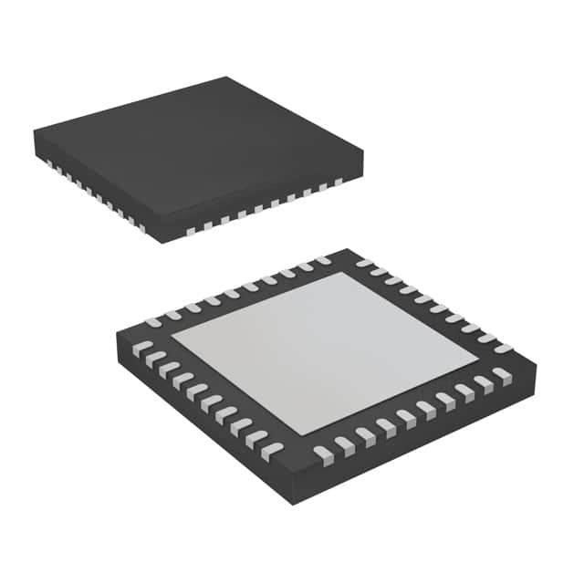
- Part No.:
- TPS53647RTAT
- Manufacturer:
- Texas Instruments
- Category:
- Special Purpose Regulators
- Package:
- 40-WFQFN Exposed Pad
- Datasheet:
-
 TPS53647RTAT.pdf
- Description:
- IC REG CTRLR VR12 1OUT 40WQFN
- Quantity:
- Payment:

- Shipping:

Inventory:564
Please send an inquiry. Send us your inquiry, and we will respond immediately.
Product details
Overview
TPS53647RTAT from Texas Instruments is a 4-phase, D-CAP+™ step-down buck controller with integrated PMBus™ interface and non-volatile memory (NVM), designed for high-current ASIC and CPU point-of-load power delivery. It supports 0.5 V to 2.5 V output voltage (5-mV steps), 300 kHz–1 MHz switching frequency, dynamic phase shedding, and accurate voltage positioning in a 6 mm × 6 mm QFN-40 package.
For engineers reviewing the TPS53647RTAT datasheet, TPS53647RTAT pinout, TPS53647RTAT application, or TPS53647RTAT equivalent, this page delivers verified technical context, validated pin functions, confirmed PMBus telemetry capabilities (voltage/current/power/temperature), and real-world selection guidance for server, telecom, and smart power system designs.
Technical Context
The TPS53647RTAT implements TI's D-CAP+™ control architecture with programmable overshoot reduction (OSR) and undershoot reduction (USR), enabling fast transient response and minimal output capacitance. Its 4-phase interleaved operation uses AutoBalance™ phase balancing and supports driverless high-frequency switching when paired with compatible NexFET™ power stages like CSD95372BQ5MC.
Configuration is supported via resistor pinstrap or PMBus commands stored in on-chip NVM, including BOOT voltage (8-bit), OCP level (16-level), slew rate (8 settings), and load-line parameters. The device reports faults-including output overvoltage, overcurrent, and thermal events-via dedicated open-drain pins (VR_FAULT, VR_HOT) and PMBus alerts.
Key Specifications
| Parameter | Value and Actual Design Meaning |
|---|---|
| Topology | 4-phase synchronous buck controller with D-CAP+™ adaptive on-time control |
| Output Voltage Range | 0.5 V to 2.5 V in 5-mV increments, set via 8-bit BOOT voltage configuration |
| Switching Frequency | 300 kHz to 1 MHz with closed-loop frequency control and programmable ramp settings |
| PMBus Interface | Fully compliant I²C-based PMBus v1.3 interface supporting telemetry of VOUT, IOUT, POUT, temperature, and fault status |
| Phase Management | Dynamic phase shedding and AutoBalance™ phase current balancing across all four phases |
| Protection Features | Programmable per-phase overcurrent (16 levels), output overvoltage, input UVLO, thermal shutdown, and fault reporting via VR_FAULT/VR_HOT pins |
| Operating Temperature | –40°C to +125°C junction temperature, qualified for industrial and server environments |
| Package | 40-pin QFN (RTA), 6.0 mm × 6.0 mm, with exposed thermal pad for enhanced thermal performance (RθJC(bot) = 1.8°C/W) |
Pinout & Package
TPS53647RTAT is housed in a thermally enhanced 40-pin QFN (RTA) package with an exposed thermal pad connected to GND. Pin functions are validated per TI SLUSC39B Rev B datasheet, including dual-purpose pins for PMBus communication, current sensing, and configuration via resistor dividers.
| Pin/Terminal | Circuit Role | Design Meaning |
|---|---|---|
| VIN | Power input | Primary input supply (4.5 V–17 V); also used for on-time calculation and input UVLO detection |
| VBOOT | Configuration input | Sets 7-bit VID for boot voltage (0.5 V–2.5 V) via resistor divider to VREF; latched at V3R3 power-up |
| CSP1–CSP4 | Current sense inputs | Positive inputs for phase current monitoring; tied to IOUT pins of compatible NexFET™ power stages (e.g., CSD95372BQ5MC) |
| PWM1–PWM4 | Gate drive outputs | Four independent PWM outputs driving external high-side FETs; support driverless operation with TI smart power stages |
| PMB_DIO / PMB_CLK / PMB_ALERT | PMBus interface | I²C-compatible bidirectional data, clock, and interrupt lines; support 1.8-V and 3.3-V logic levels |
| VR_FAULT / VR_HOT | Fault signaling | Open-drain outputs indicating critical faults (OVP, OCP, thermal) or thermal warning; pulled up externally to V3R3 |
| ISUM / COMP / VREF | Control loop interface | Summed current monitor output, error amplifier output, and 1.7-V reference for compensation and remote sensing |
Key Features
| Feature | Design Value |
|---|---|
| D-CAP+™ Control Architecture | Enables zero-output-capacitor transient response and eliminates need for external compensation components |
| AutoBalance™ Phase Balancing | Actively monitors and corrects inter-phase current imbalance in real time, improving thermal distribution and reliability |
| Programmable OSR/USR | Eight independent levels each for overshoot and undershoot reduction, configurable via O-USR pin or PMBus |
| NVM + Pinstrap Configuration | Allows persistent storage of 20+ configuration parameters (VID, OCP, frequency, slew rate) without external EEPROM |
| Driverless High-Frequency Operation | Supports >1-MHz switching with TI NexFET™ power stages by eliminating gate driver ICs and reducing layout complexity |
| PMBus Telemetry & Fault Reporting | Real-time readback of VOUT, IOUT, POUT, die temperature, and fault flags-enabling predictive maintenance and system health monitoring |
Applications
| ASIC Power Delivery | Server VR12.x/VR13.x Compliance |
|---|---|
Use Scenario: Powering high-performance ASICs in 5G baseband units requiring tight voltage regulation and rapid load-step response. IC Role / Device Role / Timing Role: Primary multi-phase buck controller managing dynamic current demands up to 200 A with PMBus-configurable load line. Use Value: D-CAP+™ control reduces output capacitance by ≥40% vs. traditional voltage-mode controllers while maintaining <±5 mV regulation under 50-A/µs transients. |
Use Scenario: Implementing VR12.5-compliant voltage regulator modules (VRMs) for dual-socket Xeon Scalable servers. IC Role / Device Role / Timing Role: PMBus-enabled digital controller supporting VR12.5 DAC mode, SVID handshake, and dynamic phase add/drop per Intel specification. Use Value: Built-in VR12.5/VR12.0 DAC mode and 5-mV VID steps enable precise compliance with Intel VRD requirements without external DACs. |
| High-Density Telecom Power | Smart Power System Monitoring |
Use Scenario: Compact, high-efficiency power solution for packet processing units in edge routers where board space is constrained. IC Role / Device Role / Timing Role: 4-phase controller operating at 800 kHz with driverless topology to minimize footprint and improve power density. Use Value: 6 mm × 6 mm QFN package with thermal pad achieves 30.6°C/W θJA, enabling >150 W output in ≤1 cm² area without forced airflow. |
Use Scenario: Real-time power health monitoring in AI accelerator cards using telemetry-driven thermal and efficiency optimization. IC Role / Device Role / Timing Role: PMBus master-slave node providing continuous VOUT/IOUT/POUT/temperature streaming to host BMC via SMBus. Use Value: On-chip NVM stores calibrated telemetry offsets, ensuring ±0.5% VOUT and ±3% IOUT accuracy across temperature without host calibration overhead. |
Equivalent & Alternatives
The following parts are listed as comparable options for similar multi-phase buck controller applications.
| Alternative Part | Technical Difference | Application Difference | Selection Advice |
|---|---|---|---|
| TPS53679RTAT | 8-phase version with identical pinout, same D-CAP+™ architecture, but higher IMAX capability (up to 120 A per phase vs. 72 A) | Required for >200 A total output current; adds two extra PWM/CSP pairs and extended NVM parameter set | Select TPS53679RTAT when scaling beyond 200 A or needing finer current granularity per phase |
| MP2964GQKT-Z | Monolithic 4-phase controller with integrated MOSFET drivers; no external power stage needed; lacks NVM and PMBus telemetry | Used in cost-sensitive, lower-power (<120 A) systems where telemetry and field reconfiguration are not required | Choose MP2964GQKT-Z for simplified BOM and layout where digital configurability and telemetry are secondary |
Compared with TPS53647RTAT, TPS53679RTAT extends phase count and current handling for higher-power ASICs, while MP2964GQKT-Z trades configurability and telemetry for integration and cost-making TPS53647RTAT optimal for balanced performance, intelligence, and scalability in enterprise-class power systems.
Availability
TPS53647RTAT is available at Aetrix Electronics and suitable for server power, telecom infrastructure, and smart power system designs requiring stable component supply, long-term lifecycle support, and traceable sourcing.
Supply support for TPS53647RTAT includes scheduled delivery planning, volume procurement assistance, BOM continuity management, traceable sourcing, and lifecycle availability coordination for OEM customers, industrial embedded developers, connected-device designers, and electronics production programs.
Manufacturer
Texas Instruments is a global semiconductor leader specializing in analog, embedded processing, and power management technologies, with decades of expertise in high-efficiency DC/DC conversion.
The TPS53647RTAT belongs to TI's Fusion Digital Power™ controller family, engineered specifically for intelligent, high-current point-of-load applications in datacenter, networking, and AI hardware where precision, telemetry, and thermal resilience are critical.
FAQ
What is the maximum output current supported by the TPS53647RTAT?
The TPS53647RTAT itself is a controller-not a power stage-so its current capability depends on the selected external power stage. When paired with TI's CSD95372BQ5MC NexFET™ power stage, the TPS53647RTAT enables up to 200 A total output current across four phases. Each phase supports up to 72 A peak current, as defined by the OCL-R pin configuration and internal current-sense gain (1.0 V/V). The controller's IMAX setting (via F-IMAX pin) scales dynamically from 18 A to 122 A per phase based on resistor selection.
Does the TPS53647RTAT support VR12.5 and VR12.0 standards?
Yes, the TPS53647RTAT natively supports both VR12.5 and VR12.0 standards. Its SLEW-MODE pin configures DAC mode (bit 7), and VID step size is 5 mV for VR12.0 and 10 mV for VR12.5-matching Intel's specifications. The device implements closed-loop VSP tolerance within ±0.6% for VR12.0 and ±1.0% for VR12.5 across –40°C to 125°C, and supports SVID handshake via PMBus for full VR compliance in server platforms.
How is the TPS53647RTAT configured-through pins or software?
The TPS53647RTAT supports dual-mode configuration: resistor pinstrapping (for factory-set defaults) and PMBus commands (for runtime or field updates). Key parameters-including BOOT voltage, OCP threshold, switching frequency, slew rate, OSR/USR levels, and load-line coefficients-are stored in on-chip non-volatile memory (NVM). TI's Fusion Digital Power Designer GUI provides full graphical configuration, validation, and telemetry logging for the TPS53647RTAT during development and deployment.
Can the TPS53647RTAT operate with only one or two phases active?
Yes, the TPS53647RTAT supports 1-, 2-, 3-, or 4-phase operation dynamically. Phase count is selected at startup via pinstrap (SKIP-NVM pin) or programmed via PMBus command MFR_SPECIFIC_01[1:0]. Dynamic phase shedding is enabled by default and activates automatically when load current falls below the programmable IMAX threshold, improving light-load efficiency without compromising transient response.
What thermal performance can be expected from the TPS53647RTAT in a typical 4-layer PCB layout?
In a standard 4-layer PCB with 2 oz copper, 6 thermal vias under the exposed pad, and 1 in² copper pour, the TPS53647RTAT achieves a junction-to-board thermal resistance (RθJB) of 6.9°C/W and junction-to-ambient (RθJA) of 30.6°C/W. At 12 V input and 1.0 V/100 A output, typical power dissipation is ~3.2 W, resulting in <100°C junction rise above ambient-well within the –40°C to 125°C operating range. Layout guidelines emphasize low-inductance GND connections and proper decoupling at VIN, V5, and V3R3.
TPS53647RTAT Specifications
- Product attributes
- Attribute value
- Manufacturer:
- Texas Instruments
- Series:
- D-CAP+™
- Package/Case:
- 40-WFQFN Exposed Pad
- Packaging:
- Tape & Reel (TR)
- Product Status:
- Active
- Applications:
- Controller, Intel VR12, VR12.5
- Voltage - Input:
- 4.5V ~ 17V
- Number of Outputs:
- 1
- Voltage - Output:
- 0.25V ~ 1.52V
- Operating Temperature:
- -40°C ~ 125°C
- Grade:
- -
- Qualification:
- -
- Mounting Type:
- Surface Mount
- Supplier Device Package:
- 40-WQFN (6x6)
TPS53647RTAT FAQ
1.How can I place an order for TPS53647RTAT through Aetrix?
Please submit a Request for Quotation (RFQ) for TPS53647RTAT on Aetrix. Our sales agent will provide a competitive quotation and guide you through the order confirmation once you accept the terms.
2.Are the price and stock information for TPS53647RTAT reliable?
The price and inventory of TPS53647RTAT are updated periodically and may fluctuate due to market conditions. Stock and pricing data are typically refreshed every 24 hours. Quotation validity for TPS53647RTAT is usually 5 days.
3.What payment methods are accepted for TPS53647RTAT?
We accept Wire Transfer, PayPal, Credit Card, Western Union, MoneyGram, and Escrow for TPS53647RTAT transactions.
Note: Certain payment methods may incur a processing fee.
4.How is shipping managed for TPS53647RTAT?
TPS53647RTAT orders can be shipped via leading logistics carriers, including DHL, UPS, FedEx, TNT, or Registered Mail.
Once your TPS53647RTAT order is processed, you will receive an email with the shipment details and tracking number.
Note: Tracking information may take up to 24 hours to appear. Express delivery typically takes 3–5 business days.
5.How can I obtain technical support or documentation for TPS53647RTAT?
For technical support, including TPS53647RTAT datasheets, pinout diagrams, or application guidance, please contact our engineering support team. They can provide detailed documentation and assistance for your TPS53647RTAT requirements.
6.How does Aetrix verify that TPS53647RTAT is sourced from the original manufacturer or authorized distributors?
All TPS53647RTAT products on Aetrix are procured from qualified distributors and authorized channels. Our dedicated quality assurance team conducts strict verification, including traceability checks and, if necessary, third-party testing. This ensures that TPS53647RTAT meets industry standards.
7.What is the process for return or replacement of TPS53647RTAT?
All TPS53647RTAT units undergo pre-shipment inspection (PSI). If there is an issue with TPS53647RTAT, returns or replacements are accepted under the following conditions:
1.Quantity discrepancies, incorrect items, or visible external defects (such as breakage or corrosion), acknowledged by Aetrix.
2.The issue is reported within 90 days of delivery.
3.The TPS53647RTAT part is unused and in its original packaging.
Return procedure for TPS53647RTAT:
1.Submit a request within 90 days.
2.Obtain a Return Material Authorization (RMA) from Aetrix.
TPS53647RTAT Tags

-
TPS51206DSQR
Texas Instruments

-
TPS51200DRCR
Texas Instruments
-
TPS51200DRCT
Texas Instruments

-
TPS62740DSSR
Texas Instruments

-
TPS51100DGQR
Texas Instruments

-
NCP51200MNTXG
onsemi
-
NCP51400MNTXG
onsemi

-
RT9026GSP
Richtek USA Inc.

-
LP2998MRX/NOPB
Texas Instruments
-
TPS51200QDRCRQ1
Texas Instruments

-
DPA423GN-TL
Power Integrations
-
LM10011SD/NOPB
Texas Instruments
Tech Hub

A practical engineering guide to 3.3V and 5V logic compatibility, input thresholds, resistor dividers, translator ICs, MOSFET level shifting, I2C pull-ups, timing limits and power-sequencing risks.

The 74HC595 uses push-pull logic outputs, while the TPIC6B595 uses 50 V open-drain DMOS sinks for higher-power loads. This guide compares timing, current limits, 3.3 V interfacing, load wiring, thermal…

The 74HC595 converts serial data into eight stable parallel outputs. This guide covers pin functions, shift and storage timing, OE and MR behavior, drive-current limits, cascading, voltage compatibilit…

A technical comparison of level-sensitive latches and edge-triggered flip-flops, covering timing windows, setup and hold limits, master–slave operation, time borrowing, race-through, HDL inference and…

A D latch stores one bit while Enable controls when data can pass. This reference covers gate-level operation, truth tables, transparency, setup and hold timing, LE versus OE, common ICs and practical …

An SR latch stores one bit through cross-coupled feedback. This engineering reference covers NOR and NAND implementations, truth tables, forbidden-state recovery, gated operation, switch debouncing, fa…

Latch circuits retain one bit through feedback. This technical reference covers SR and D latches, truth tables, transparency, timing limits, latch-versus-flip-flop behavior, applications and common log…

An engineering guide to LED driver operation, constant-current and constant-voltage outputs, linear and switching topologies, dimming, IC selection, calculations, replacement compatibility, and fault c…

Operational amplifier guide covering op amp basics, feedback, ideal vs real op amps, common configurations, buffer circuits, offset, bias current, gain-bandwidth, slew rate, rail-to-rail limits and sel…

Jumper cables guide covering safe connection order, red and black clamp placement, final ground connection, cable gauge, length, clamp quality, copper vs CCA cables, jump starter comparison and battery…


