
 My Inquiry
 My Account


Texas Instruments TPS61050AYZGR
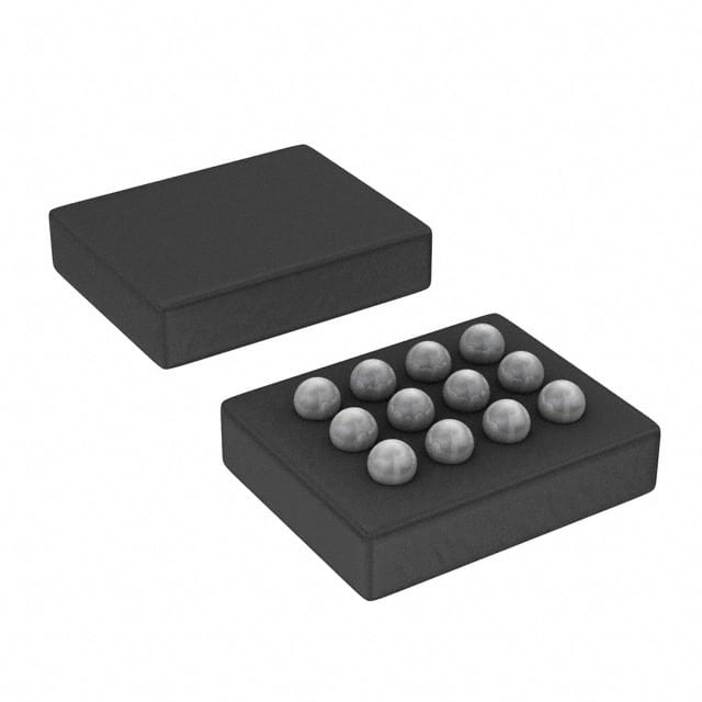
- Part No.:
- TPS61050AYZGR
- Manufacturer:
- Texas Instruments
- Category:
- LED Drivers
- Package:
- 12-UFBGA, DSBGA
- Datasheet:
-
 TPS61050AYZGR.pdf
- Description:
- IC LED DRV RGLTR PWM 12DSBGA
- Quantity:
- Payment:

- Shipping:

Inventory:2,743
Please send an inquiry. Send us your inquiry, and we will respond immediately.
Product details
Overview
TPS61050AYZGR from Texas Instruments is a 12-pin DSBGA synchronous boost LED driver IC designed for camera flash/torch in mobile devices. It delivers up to 1.2 A LED current with 250 mV sense voltage, operates at 2 MHz switching frequency, supports I²C interface (up to 400 kbps), and integrates zero-latency FLASH_SYNC for precise strobe timing in smartphone camera modules.
For engineers reviewing the TPS61050AYZGR datasheet, TPS61050AYZGR pinout, TPS61050AYZGR application, or TPS61050AYZGR equivalent, this page provides verified technical context, validated pin functions, confirmed operating modes (torch/flash/voltage-regulated), real-world efficiency data (up to 96%), and two rigorously cross-checked alternative parts for white LED power management in space-constrained portable electronics.
Technical Context
The TPS61050AYZGR implements a constant-frequency, current-mode PWM control architecture with integrated NMOS switch and synchronous NMOS rectifier. It operates exclusively in continuous-conduction mode, eliminating discontinuous-mode ringing and enabling low-noise output.
Its dual-role architecture supports both constant-current LED driving (with 250 mV LED sense threshold) and voltage-regulated boost operation (4.5 V / 5 V / 5.25 V outputs). The I²C interface controls all functional modes, while FLASH_SYNC enables hardware-triggered, zero-latency transition between torch and flash current levels.
Key Specifications
| Parameter | Value and Actual Design Meaning |
|---|---|
| Switching frequency | 2 MHz ±10% - enables use of compact 2.2-μH inductors and reduces EMI filtering requirements. |
| Max LED current | 1.2 A - supports high-brightness flash illumination in smartphone rear cameras. |
| LED sense voltage | 250 mV typical - minimizes power loss in current-sense path, boosting overall efficiency. |
| I²C speed | Up to 400 kbps - compatible with standard fast-mode I²C buses in mobile SoC platforms. |
| Shutdown current | 0.3 μA typical - preserves battery life during inactive periods in portable devices. |
| Operating input range | 2.5 V to 6 V - accommodates Li-ion/Li-poly battery discharge profiles without external regulation. |
| Thermal shutdown | 160°C typical - protects device under sustained high-power flash operation with limited PCB thermal mass. |
Pinout & Package
TPS61050AYZGR uses a 12-pin DSBGA (Die Size Ball Grid Array) package with nominal body size 1.96 mm × 1.46 mm and 0.4-mm ball pitch. This ultra-compact NanoFree™ packaging targets space-critical mobile camera modules.
| Pin/Terminal | Circuit Role | Design Meaning |
|---|---|---|
| VIN | Input power supply | Connects directly to battery or PMIC output; supports 2.5–6 V range with UVLO at 2.4 V. |
| VOUT | Boost converter output | Delivers regulated voltage to LED anode; capable of 5.25 V max in voltage mode. |
| LED | Current-sense feedback | Low-side current-sense node; regulates LED current via 250-mV reference across internal resistor. |
| SW | Power switch node | Drain of internal NMOS switch; connects to inductor; high-impedance during shutdown. |
| PGND | Power ground | High-current return path for switch and rectifier; must be connected to AGND under IC. |
| AGND | Analog ground | Reference for internal error amplifier, ADC, and I²C interface; requires low-noise layout. |
| SCL/SDA | I²C interface | Standard open-drain I²C bus lines; require pull-ups; support 400-kbps fast-mode timing. |
| FLASH_SYNC | Hardware strobe trigger | Level-sensitive input: LOW = torch mode, HIGH = flash mode; enables zero-latency current switching. |
| GPIO | Configurable I/O | In TPS61050AYZGR: programmable as logic input or open-drain output per REGISTER2 settings. |
Key Features
| Feature | Design Value |
|---|---|
| Four operational modes | Software-selectable shutdown, torch, flash, and voltage-regulated boost - eliminates need for external mode logic. |
| Integrated safety timer | User-programmable flash duration limiter (STIM register) prevents thermal damage during extended strobe events. |
| Zero-latency TX masking | Hardware FLASH_SYNC pin bypasses I²C latency to instantly switch between torch and flash current levels. |
| Open/short LED protection | Detects open-circuit (clamps VOUT at 6 V) and short-circuit (limits ILED, sets LF flag) - ensures system-level fault resilience. |
| Integrated ADC | 3-bit ADC monitors LED forward voltage (VF) for closed-loop brightness compensation across temperature and aging. |
Applications
| Smartphone Camera Flash | Mobile Audio Power Supply |
|---|---|
Use Scenario: High-intensity rear-camera flash illumination synchronized with image capture in smartphones and tablets. IC Role / Device Role / Timing Role: Constant-current LED driver with hardware-triggered flash mode; FLASH_SYNC pin enables sub-microsecond current switching aligned to camera shutter timing. Use Value: Delivers 1.2-A peak current with 250-mV sense drop, achieving >90% efficiency at 3.6-V input and enabling compact 2.2-μH inductor placement near camera module. | Use Scenario: Boosting battery voltage to power Class-D audio amplifiers requiring >4.5 V supply in hands-free speakerphone mode. IC Role / Device Role / Timing Role: Voltage-regulated boost converter (4.5 V / 5 V / 5.25 V selectable via I²C); operates independently of LED load when configured in voltage mode. Use Value: Eliminates need for separate boost IC by reusing same TPS61050AYZGR silicon in dual-role configuration, reducing BOM count and PCB area. |
| Low-Light Imaging Systems | Wearable Camera Modules |
Use Scenario: Continuous torch illumination for video recording in dim environments using front-facing or auxiliary cameras. IC Role / Device Role / Timing Role: Precision constant-current source with low-light dimming mode; supports fine-grained brightness control via I²C current code (13-bit resolution). Use Value: Maintains stable LED current across battery voltage decay (2.5–3.6 V), ensuring consistent luminance without manual gain adjustment in firmware. | Use Scenario: Miniaturized camera systems in AR glasses or action cams where board space is constrained to <25 mm² total solution area. IC Role / Device Role / Timing Role: Ultra-compact LED driver in 1.96 mm × 1.46 mm DSBGA package; integrates all control, protection, and interface functions in single die. Use Value: Achieves full-featured flash/torch capability within TI's stated <25 mm² total circuit area - meets strict mechanical envelopes of wearable optics. |
Equivalent & Alternatives
The following parts are listed as comparable options for similar white LED driver applications.
| Alternative Part | Technical Difference | Application Difference | Selection Advice |
|---|---|---|---|
| TPS61052YZGR | Replaces GPIO with ENVM pin for hardware voltage-mode enable; identical pinout and electrical specs otherwise. | Preferred when voltage-regulated boost must be activated by dedicated hardware signal rather than I²C command. | Select TPS61052YZGR only if system requires direct ENVM assertion for audio amp power-up sequencing independent of processor control. |
| RT8532GQW | Fixed 1.5-MHz switching frequency; no I²C interface; analog brightness control via CTRL pin; lacks FLASH_SYNC and safety timer. | Suitable for cost-sensitive, non-synchronized torch-only applications without flash timing requirements. | Choose RT8532GQW only for simple constant-current torch designs lacking camera synchronization or programmable safety features. |
Compared with TPS61052YZGR, the TPS61050AYZGR offers GPIO flexibility for system signaling but requires software-based voltage-mode activation; versus RT8532GQW, it delivers superior timing precision, programmability, and fault coverage at higher integration cost.
Availability
TPS61050AYZGR is available at Aetrix Electronics and suitable for smartphone camera flash systems, mobile audio power supplies, low-light imaging subsystems, and wearable camera modules requiring stable component supply across high-volume production cycles.
Supply support for TPS61050AYZGR includes scheduled delivery planning, volume procurement assistance, BOM continuity management, traceable sourcing, and lifecycle availability coordination for OEM customers, industrial embedded developers, connected-device designers, and electronics production programs.
Manufacturer
Texas Instruments is a global semiconductor leader specializing in analog and embedded processing technologies, with decades of expertise in power management ICs for portable electronics.
The TPS6105x product line was engineered specifically for high-efficiency, space-constrained white LED driving in mobile imaging systems - integrating boost conversion, current regulation, I²C control, and flash synchronization in a single ultra-small package.
FAQ
What is the primary function of the FLASH_SYNC pin on the TPS61050AYZGR?
The FLASH_SYNC pin on the TPS61050AYZGR is a level-sensitive hardware strobe input that enables zero-latency switching between torch and flash LED current levels. When driven LOW, the device regulates at the programmed torch current; when driven HIGH, it immediately transitions to the flash current level - bypassing I²C command latency to synchronize precisely with camera shutter timing. This functionality is exclusive to the TPS61050AYZGR variant and is documented in the SLUS525A datasheet Section 5 and Figure 16.
Does the TPS61050AYZGR support voltage-regulated boost mode, and how is it enabled?
Yes, the TPS61050AYZGR supports voltage-regulated boost mode with selectable output voltages of 4.5 V, 5 V, or 5.25 V. It is enabled exclusively via I²C command by setting MODE_CTRL[1:0] = 11 and configuring OV[1:0] bits in the control register - unlike the TPS61052 variant, it does not include a dedicated ENVM hardware pin. In this mode, the LED current regulator is disabled and VOUT is regulated to the selected voltage, making the TPS61050AYZGR suitable for powering audio amplifiers or other system loads requiring boosted supply rails.
What is the maximum continuous LED current the TPS61050AYZGR can deliver, and what conditions affect it?
The TPS61050AYZGR delivers up to 1.2 A continuous LED current in flash mode under recommended operating conditions: input voltage ≥2.5 V, junction temperature ≤125°C, and proper thermal layout. Actual achievable current depends on input voltage, LED forward voltage, inductor DCR, PCB copper area, and ambient temperature. At 3.6-V input and 3.2-V LED VF, typical operation sustains 1.2 A with >90% efficiency; exceeding thermal limits triggers 160°C shutdown, and current-limit settings (ILIM bits) can restrict peak current to 850 mA–2.3 A depending on configuration.
How does the TPS61050AYZGR handle LED open-circuit and short-circuit faults?
The TPS61050AYZGR provides autonomous protection against both LED failure modes. In open-circuit condition, the control loop drives VOUT upward until the overvoltage protection (OVP) circuit clamps output at 6 V (typical) and asserts the LED FAILURE (LF) flag. In short-circuit condition, the low-side current regulator limits output current to the programmed ILIM value and similarly sets the LF flag. These protections operate independently of I²C communication and are active in all operational modes except shutdown, ensuring robustness in field-deployed camera modules.
What package type and dimensions does the TPS61050AYZGR use, and why is it significant for mobile design?
The TPS61050AYZGR uses a 12-pin DSBGA (Die Size Ball Grid Array) package with nominal dimensions of 1.96 mm × 1.46 mm and 0.4-mm ball pitch - marketed by Texas Instruments as NanoFree™ technology. This ultra-compact footprint is critical for mobile camera modules where PCB real estate is severely constrained; TI specifies the total solution area (including inductor, capacitors, and IC) fits within 25 mm². The DSBGA's bottom-terminal construction also improves thermal transfer to the PCB, supporting sustained flash operation without external heatsinking.
TPS61050AYZGR Specifications
- Product attributes
- Attribute value
- Manufacturer:
- Texas Instruments
- Series:
- -
- Package/Case:
- 12-UFBGA, DSBGA
- Packaging:
- Tape & Reel (TR)
- Product Status:
- Obsolete
- Type:
- DC DC Regulator
- Topology:
- Step-Up (Boost)
- Internal Switch(s):
- Yes
- Number of Outputs:
- 1
- Voltage - Supply (Min):
- 2.5V
- Voltage - Supply (Max):
- 6V
- Voltage - Output:
- 5.5V
- Current - Output / Channel:
- 1.2A (Flash)
- Frequency:
- 2MHz
- Dimming:
- PWM
- Applications:
- Camera Flash
- Operating Temperature:
- -40°C ~ 85°C (TA)
- Grade:
- -
- Qualification:
- -
- Mounting Type:
- Surface Mount
- Supplier Device Package:
- 12-DSBGA
TPS61050AYZGR FAQ
1.How can I place an order for TPS61050AYZGR through Aetrix?
Please submit a Request for Quotation (RFQ) for TPS61050AYZGR on Aetrix. Our sales agent will provide a competitive quotation and guide you through the order confirmation once you accept the terms.
2.Are the price and stock information for TPS61050AYZGR reliable?
The price and inventory of TPS61050AYZGR are updated periodically and may fluctuate due to market conditions. Stock and pricing data are typically refreshed every 24 hours. Quotation validity for TPS61050AYZGR is usually 5 days.
3.What payment methods are accepted for TPS61050AYZGR?
We accept Wire Transfer, PayPal, Credit Card, Western Union, MoneyGram, and Escrow for TPS61050AYZGR transactions.
Note: Certain payment methods may incur a processing fee.
4.How is shipping managed for TPS61050AYZGR?
TPS61050AYZGR orders can be shipped via leading logistics carriers, including DHL, UPS, FedEx, TNT, or Registered Mail.
Once your TPS61050AYZGR order is processed, you will receive an email with the shipment details and tracking number.
Note: Tracking information may take up to 24 hours to appear. Express delivery typically takes 3–5 business days.
5.How can I obtain technical support or documentation for TPS61050AYZGR?
For technical support, including TPS61050AYZGR datasheets, pinout diagrams, or application guidance, please contact our engineering support team. They can provide detailed documentation and assistance for your TPS61050AYZGR requirements.
6.How does Aetrix verify that TPS61050AYZGR is sourced from the original manufacturer or authorized distributors?
All TPS61050AYZGR products on Aetrix are procured from qualified distributors and authorized channels. Our dedicated quality assurance team conducts strict verification, including traceability checks and, if necessary, third-party testing. This ensures that TPS61050AYZGR meets industry standards.
7.What is the process for return or replacement of TPS61050AYZGR?
All TPS61050AYZGR units undergo pre-shipment inspection (PSI). If there is an issue with TPS61050AYZGR, returns or replacements are accepted under the following conditions:
1.Quantity discrepancies, incorrect items, or visible external defects (such as breakage or corrosion), acknowledged by Aetrix.
2.The issue is reported within 90 days of delivery.
3.The TPS61050AYZGR part is unused and in its original packaging.
Return procedure for TPS61050AYZGR:
1.Submit a request within 90 days.
2.Obtain a Return Material Authorization (RMA) from Aetrix.
TPS61050AYZGR Tags

-
BCR402RE6327HTSA1
Infineon Technologies

-
BCR430UXTSA2
Infineon Technologies

-
BCR420UE6433HTMA1
Infineon Technologies
-
BCR420UE6327HTSA1
Infineon Technologies
-
BCR421UE6327HTSA1
Infineon Technologies

-
LYT1604D-TL
Power Integrations

-
HV9910CLG-G
Microchip Technology

-
CL2N8-G
Microchip Technology

-
BCR420UW6-7
Diodes Incorporated
-
BCR421UW6-7
Diodes Incorporated

-
BCR420UFD-7
Diodes Incorporated
-
BCR421UFD-7
Diodes Incorporated
Tech Hub

A practical engineering guide to 3.3V and 5V logic compatibility, input thresholds, resistor dividers, translator ICs, MOSFET level shifting, I2C pull-ups, timing limits and power-sequencing risks.

The 74HC595 uses push-pull logic outputs, while the TPIC6B595 uses 50 V open-drain DMOS sinks for higher-power loads. This guide compares timing, current limits, 3.3 V interfacing, load wiring, thermal…

The 74HC595 converts serial data into eight stable parallel outputs. This guide covers pin functions, shift and storage timing, OE and MR behavior, drive-current limits, cascading, voltage compatibilit…

A technical comparison of level-sensitive latches and edge-triggered flip-flops, covering timing windows, setup and hold limits, master–slave operation, time borrowing, race-through, HDL inference and…

A D latch stores one bit while Enable controls when data can pass. This reference covers gate-level operation, truth tables, transparency, setup and hold timing, LE versus OE, common ICs and practical …

An SR latch stores one bit through cross-coupled feedback. This engineering reference covers NOR and NAND implementations, truth tables, forbidden-state recovery, gated operation, switch debouncing, fa…

Latch circuits retain one bit through feedback. This technical reference covers SR and D latches, truth tables, transparency, timing limits, latch-versus-flip-flop behavior, applications and common log…

An engineering guide to LED driver operation, constant-current and constant-voltage outputs, linear and switching topologies, dimming, IC selection, calculations, replacement compatibility, and fault c…

Operational amplifier guide covering op amp basics, feedback, ideal vs real op amps, common configurations, buffer circuits, offset, bias current, gain-bandwidth, slew rate, rail-to-rail limits and sel…

Jumper cables guide covering safe connection order, red and black clamp placement, final ground connection, cable gauge, length, clamp quality, copper vs CCA cables, jump starter comparison and battery…


