
 My Inquiry
 My Account


Texas Instruments TPS61305YFFR
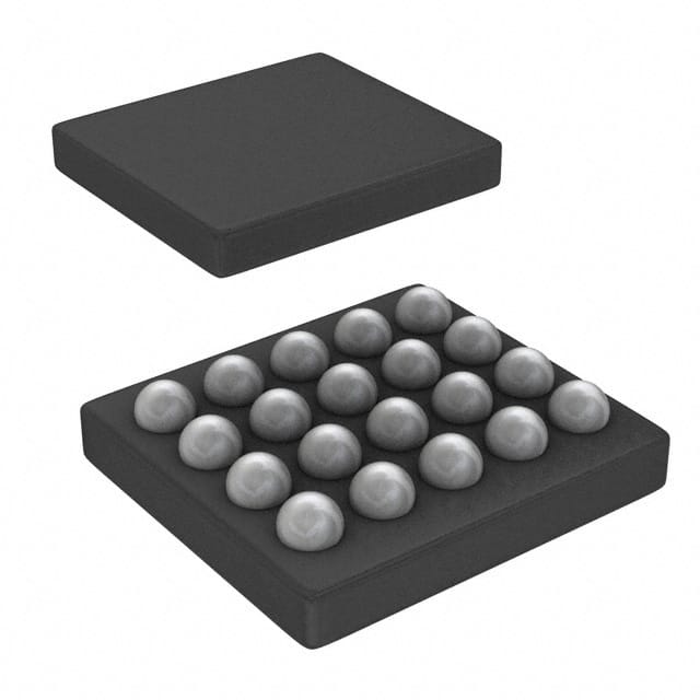
- Part No.:
- TPS61305YFFR
- Manufacturer:
- Texas Instruments
- Category:
- LED Drivers
- Package:
- 20-UFBGA, DSBGA
- Datasheet:
-
 TPS61305YFFR.pdf
- Description:
- IC LED DRV RGLTR I2C 20DSBGA
- Quantity:
- Payment:

- Shipping:

Inventory:4,764
Please send an inquiry. Send us your inquiry, and we will respond immediately.
Product details
Overview
TPS61305YFFR from Texas Instruments is a 1.5-A/4.1-A multiple LED camera flash driver IC with I²C interface, synchronous boost topology, and integrated LED current regulation for up to three white LEDs. It delivers 400 mA (LED1), 800 mA (LED2), and 400 mA (LED3) in standard mode or 925/1850/925 mA in extended high-current mode, with 400-mV LED sense voltage and 2-MHz switching frequency. It supports flashlight synchronization via FLASH_SYNC pin and operates from 2.5 V to 5.5 V input for smartphone camera flash applications.
For engineers reviewing the TPS61305YFFR datasheet, TPS61305YFFR pinout, TPS61305YFFR application, or TPS61305YFFR equivalent, key selection criteria include LED current accuracy (±7.5% flash mode), thermal shutdown (140–160°C), standby current (2–12 μA), and I²C compatibility up to 3.4 Mbits/s - all critical for compact, battery-sensitive mobile imaging systems.
Technical Context
The TPS61305YFFR implements a high-frequency synchronous boost converter with constant-current sinks per LED channel, enabling precise parallel drive of three white LEDs. Its dual-mode operation-voltage-regulated boost (3.825–5.7 V output) and current-regulated flash-allows seamless transition between DC light and strobe modes without external circuitry.
Hardware features include dedicated NRESET for system-level reset, TS pin for NTC-based LED temperature monitoring (44.5 kΩ warning threshold), and Tx-MASK for RF PA coordination. The device enters power-save mode at light loads and maintains regulated output even when input exceeds nominal VOUT, eliminating need for external overvoltage clamping.
Key Specifications
| Parameter | Value and Actual Design Meaning |
|---|---|
| Input Voltage Range | 2.5 V to 5.5 V - supports single-cell Li-ion and Li-poly battery operation without pre-regulation. |
| Max Flash Current (LED2) | 1850 mA - enables high-intensity xenon-replacement flash in energy-storage mode with HC_SEL = HIGH. |
| LED Sense Voltage | 400 mV - low dropout improves efficiency and reduces thermal stress on current-sense resistors. |
| I²C Speed | Up to 3.4 Mbits/s - supports high-speed configuration updates during camera startup and mode switching. |
| Standby Current | 2–12 μA - minimizes battery drain during idle periods in always-on imaging subsystems. |
| Switching Frequency | 1.92 MHz - allows use of compact 2.2-μH inductors and reduces EMI filtering requirements. |
| Thermal Shutdown | 140–160°C - protects LED and IC under sustained high-current flash operation with 20°C hysteresis. |
Pinout & Package
TPS61305YFFR is housed in a 20-pin NanoFree™ DSBGA package (1.90 mm × 2.20 mm, 0.5-mm pitch) with bottom-side solder balls. Thermal performance is optimized via PGND and AGND connections and low RθJA (70.9°C/W).
| Pin/Terminal | Circuit Role | Design Meaning |
|---|---|---|
| AVIN | Power Input | Main supply input; requires local 10-μF ceramic bypass capacitor for stability and transient response. |
| VOUT | Boost Output | Regulated output node feeding storage capacitor and LED anodes; supports up to 5.7 V. |
| LED1/LED2/LED3 | Current-Sink Returns | Feedback inputs regulating LED current via internal 400-mV reference; connect to LED cathodes. |
| SW | Power Switch Node | Connection to inductor switch node; carries high di/dt; requires tight layout and Kelvin routing. |
| NRESET | Hardware Reset | Active-low master reset; forces shutdown and clears I²C interface state upon assertion. |
| TS | Temperature Sense | NTC bias input (23.8 μA source); monitors LED junction temperature using 44.5 kΩ warning threshold. |
| FLASH_SYNC | Strobe Trigger | Zero-latency synchronization input; rising edge initiates immediate flash current ramp-up. |
| SCL/SDA | I²C Interface | Standard two-wire serial bus; supports fast-mode (400 kHz) and high-speed mode (3.4 MHz). |
| HC_SEL | Mode Control | Selects standard (LOW) or extended high-current (HIGH) LED drive capability; must be terminated. |
| PGND/AGND | Ground Returns | Separate power and analog grounds; require low-inductance connection under die for noise immunity. |
Key Features
| Feature | Design Value |
|---|---|
| Integrated LED Safety Timer | Prevents thermal runaway by automatically terminating flash after programmable duration, independent of host control. |
| Automatic VF and ESR Calibration | Compensates for LED forward-voltage drift and storage-capacitor ESR variation across temperature and aging, maintaining consistent flash intensity. |
| Privacy Indicator LED Output (INDLED) | Dedicated constant-current sink (2.6–7.9 mA) drives status LED to signal active camera operation, meeting privacy compliance requirements. |
| Storage Capacitor Friendly Architecture | Enables use of supercapacitors as energy reservoirs; balances dual-cell stacks via BAL pin to extend flash cycle life and capacity utilization. |
| Zero Latency Tx-Masking | Hardware input (Tx-MASK) instantly switches LED from flash to DC light mode (<15 μs settling), reducing peak battery current during RF transmission. |
Applications
| Smartphone Camera Flash | Xenon Replacement Module |
|---|---|
Use Scenario: Dual-LED or triple-LED flash circuit in flagship smartphones requiring synchronized strobe illumination with sub-millisecond latency. IC Role / Device Role / Timing Role: Primary flash driver IC managing LED current regulation, storage capacitor charging, and I²C-configurable timing parameters. Use Value: Delivers 1850-mA peak current to LED2 with ±7.5% accuracy and 400-μs flash settling time, enabling high-CRI, low-noise still capture. | Use Scenario: Compact, low-profile flash module replacing xenon tubes in portable medical endoscopes and industrial inspection cameras. IC Role / Device Role / Timing Role: High-efficiency boost + current sink controller supporting energy storage and thermal-safe multi-pulse operation. Use Value: Achieves >95% efficiency in power-save mode and integrates LED temperature monitoring (TS pin) to prevent overheating during repeated flash bursts. |
| Mobile Audio Amplifier Supply | Privacy-Compliant Imaging System |
Use Scenario: Boost power supply for Class-D audio amplifiers in smartphones, where clean, regulated 5-V rail is required during simultaneous flash and audio playback. IC Role / Device Role / Timing Role: Voltage-regulated boost converter (3.825–5.7 V) operating in parallel with LED current regulation path. Use Value: Maintains stable VOUT even when AVIN exceeds nominal output (e.g., 4.2 V battery), eliminating need for external LDO or overvoltage protection. | Use Scenario: Embedded vision system in smart doorbells or conferencing devices requiring visual indication of active camera recording. IC Role / Device Role / Timing Role: Dual-function IC providing both flash drive and privacy indicator (INDLED) with hardware-enforced enable/disable logic. Use Value: INDLED output drives dedicated red LED with 2.6–7.9 mA constant current, satisfying GDPR/CCPA visual notification mandates without additional components. |
Equivalent & Alternatives
The following parts are listed as comparable options for similar LED flash driver applications.
| Alternative Part | Technical Difference | Application Difference | Selection Advice |
|---|---|---|---|
| TPS61305AYFFR | Includes identical LED current specs and TS functionality but adds enhanced thermal detection thresholds and improved ESD robustness (±500 V CDM). | Preferred for designs requiring tighter thermal warning margin (39–50 kΩ vs 44.5 kΩ nominal) and higher manufacturing ESD immunity. | Select TPS61305AYFFR when production environment demands higher CDM tolerance or finer-grained LED temperature binning. |
| TPS61301YFFR | Lacks TS pin and LED temperature monitoring; retains NRESET, FLASH_SYNC, and same current capabilities (925/1850/925 mA). | Suitable for cost-sensitive camera modules where thermal derating is managed externally or not required. | Choose TPS61301YFFR only if LED thermal monitoring is unnecessary and BOM simplification is prioritized over safety diagnostics. |
Compared with TPS61305YFFR, TPS61305AYFFR offers tighter thermal sensing resolution and higher CDM rating, while TPS61301YFFR removes temperature monitoring entirely - making the original TPS61305YFFR the optimal balance of integrated safety, flash performance, and design flexibility for premium mobile imaging.
Availability
TPS61305YFFR is available at Aetrix Electronics and suitable for smartphone camera flash, mobile audio amplifier supply, and privacy-compliant imaging systems requiring stable component supply, full lifecycle support, and traceable sourcing.
Supply support for TPS61305YFFR includes scheduled delivery planning, volume procurement assistance, BOM continuity management, traceable sourcing, and lifecycle availability coordination for OEM customers, industrial embedded developers, connected-device designers, and electronics production programs.
Manufacturer
Texas Instruments is a global semiconductor leader specializing in analog, embedded processing, and connectivity technologies with broad industrial and consumer design expertise.
The TPS6130xx product line was engineered specifically for high-efficiency, space-constrained LED flash applications in mobile devices, integrating boost conversion, current regulation, thermal safety, and I²C control in a single NanoFree™ package.
FAQ
What is the maximum flash current capability of the TPS61305YFFR in extended high-current mode?
The TPS61305YFFR delivers up to 925 mA on LED1, 1850 mA on LED2, and 925 mA on LED3 when HC_SEL is asserted HIGH. This extended mode leverages energy stored in the output capacitor to achieve xenon-equivalent intensity without exceeding battery peak current limits. The TPS61305YFFR achieves this using internal valley-current limiting and adaptive PWM control, validated across –40°C to 125°C junction temperature.
Does the TPS61305YFFR support automatic LED temperature compensation?
Yes, the TPS61305YFFR supports LED temperature monitoring via its TS pin, which sources 23.8 μA to bias an external NTC thermistor. When the thermistor resistance drops to 44.5 kΩ (typical), the LEDWARN bit is set; at 14.5 kΩ, LEDHOT triggers protective action. This function is exclusive to TPS61305YFFR and TPS61305AYFFR variants - not present in TPS61300 or TPS61301.
How does the FLASH_SYNC pin reduce flash latency in the TPS61305YFFR?
The FLASH_SYNC pin provides hardware-triggered zero-latency flash activation: a rising edge forces immediate transition from DC light to full flash current, with LED2 settling in 400 μs (HC_SEL = LOW) or 16 μs (HC_SEL = HIGH). This bypasses I²C command overhead and ensures precise synchronization with camera shutter timing - a feature confirmed in the TPS61305YFFR's timing specifications table (Section 7.6).
Can the TPS61305YFFR operate as a standard voltage regulator without driving LEDs?
Yes, the TPS61305YFFR can operate in standalone voltage regulation mode by asserting ENVM HIGH, setting VOUT to a fixed 4.95 V with ±2% accuracy. In this mode, LEDx pins are disabled, and the device regulates output using internal feedback - verified in Section 7.5 Electrical Characteristics under "Internal feedback voltage accuracy" and "Voltage regulation mode" test conditions.
What is the purpose of the BAL pin on the TPS61305YFFR?
The BAL pin on the TPS61305YFFR provides active cell balancing for dual-cell supercapacitor configurations. It sinks or sources up to ±15 mA to equalize leakage current mismatch between series-connected storage capacitors, maintaining voltage balance within ±100 mV at 5.7 V VOUT. This extends usable flash energy and cycle life - a capability documented in the "Storage Capacitor Active Cell Balancing" subsection of Section 7.5.
TPS61305YFFR Specifications
- Product attributes
- Attribute value
- Manufacturer:
- Texas Instruments
- Series:
- -
- Package/Case:
- 20-UFBGA, DSBGA
- Packaging:
- Tape & Reel (TR)
- Product Status:
- Active
- Type:
- DC DC Regulator
- Topology:
- Step-Up (Boost)
- Internal Switch(s):
- Yes
- Number of Outputs:
- 3
- Voltage - Supply (Min):
- 2.5V
- Voltage - Supply (Max):
- 5.5V
- Voltage - Output:
- 5.7V
- Current - Output / Channel:
- 400mA, 800mA (Flash)
- Frequency:
- 1.92MHz
- Dimming:
- I2C
- Applications:
- Camera Flash
- Operating Temperature:
- -40°C ~ 85°C (TA)
- Grade:
- -
- Qualification:
- -
- Mounting Type:
- Surface Mount
- Supplier Device Package:
- 20-DSBGA
TPS61305YFFR FAQ
1.How can I place an order for TPS61305YFFR through Aetrix?
Please submit a Request for Quotation (RFQ) for TPS61305YFFR on Aetrix. Our sales agent will provide a competitive quotation and guide you through the order confirmation once you accept the terms.
2.Are the price and stock information for TPS61305YFFR reliable?
The price and inventory of TPS61305YFFR are updated periodically and may fluctuate due to market conditions. Stock and pricing data are typically refreshed every 24 hours. Quotation validity for TPS61305YFFR is usually 5 days.
3.What payment methods are accepted for TPS61305YFFR?
We accept Wire Transfer, PayPal, Credit Card, Western Union, MoneyGram, and Escrow for TPS61305YFFR transactions.
Note: Certain payment methods may incur a processing fee.
4.How is shipping managed for TPS61305YFFR?
TPS61305YFFR orders can be shipped via leading logistics carriers, including DHL, UPS, FedEx, TNT, or Registered Mail.
Once your TPS61305YFFR order is processed, you will receive an email with the shipment details and tracking number.
Note: Tracking information may take up to 24 hours to appear. Express delivery typically takes 3–5 business days.
5.How can I obtain technical support or documentation for TPS61305YFFR?
For technical support, including TPS61305YFFR datasheets, pinout diagrams, or application guidance, please contact our engineering support team. They can provide detailed documentation and assistance for your TPS61305YFFR requirements.
6.How does Aetrix verify that TPS61305YFFR is sourced from the original manufacturer or authorized distributors?
All TPS61305YFFR products on Aetrix are procured from qualified distributors and authorized channels. Our dedicated quality assurance team conducts strict verification, including traceability checks and, if necessary, third-party testing. This ensures that TPS61305YFFR meets industry standards.
7.What is the process for return or replacement of TPS61305YFFR?
All TPS61305YFFR units undergo pre-shipment inspection (PSI). If there is an issue with TPS61305YFFR, returns or replacements are accepted under the following conditions:
1.Quantity discrepancies, incorrect items, or visible external defects (such as breakage or corrosion), acknowledged by Aetrix.
2.The issue is reported within 90 days of delivery.
3.The TPS61305YFFR part is unused and in its original packaging.
Return procedure for TPS61305YFFR:
1.Submit a request within 90 days.
2.Obtain a Return Material Authorization (RMA) from Aetrix.
TPS61305YFFR Tags

-
BCR402RE6327HTSA1
Infineon Technologies

-
BCR430UXTSA2
Infineon Technologies

-
BCR420UE6433HTMA1
Infineon Technologies
-
BCR420UE6327HTSA1
Infineon Technologies
-
BCR421UE6327HTSA1
Infineon Technologies

-
LYT1604D-TL
Power Integrations

-
HV9910CLG-G
Microchip Technology

-
CL2N8-G
Microchip Technology

-
BCR420UW6-7
Diodes Incorporated
-
BCR421UW6-7
Diodes Incorporated

-
BCR420UFD-7
Diodes Incorporated
-
BCR421UFD-7
Diodes Incorporated
Tech Hub

A practical engineering guide to 3.3V and 5V logic compatibility, input thresholds, resistor dividers, translator ICs, MOSFET level shifting, I2C pull-ups, timing limits and power-sequencing risks.

The 74HC595 uses push-pull logic outputs, while the TPIC6B595 uses 50 V open-drain DMOS sinks for higher-power loads. This guide compares timing, current limits, 3.3 V interfacing, load wiring, thermal…

The 74HC595 converts serial data into eight stable parallel outputs. This guide covers pin functions, shift and storage timing, OE and MR behavior, drive-current limits, cascading, voltage compatibilit…

A technical comparison of level-sensitive latches and edge-triggered flip-flops, covering timing windows, setup and hold limits, master–slave operation, time borrowing, race-through, HDL inference and…

A D latch stores one bit while Enable controls when data can pass. This reference covers gate-level operation, truth tables, transparency, setup and hold timing, LE versus OE, common ICs and practical …

An SR latch stores one bit through cross-coupled feedback. This engineering reference covers NOR and NAND implementations, truth tables, forbidden-state recovery, gated operation, switch debouncing, fa…

Latch circuits retain one bit through feedback. This technical reference covers SR and D latches, truth tables, transparency, timing limits, latch-versus-flip-flop behavior, applications and common log…

An engineering guide to LED driver operation, constant-current and constant-voltage outputs, linear and switching topologies, dimming, IC selection, calculations, replacement compatibility, and fault c…

Operational amplifier guide covering op amp basics, feedback, ideal vs real op amps, common configurations, buffer circuits, offset, bias current, gain-bandwidth, slew rate, rail-to-rail limits and sel…

Jumper cables guide covering safe connection order, red and black clamp placement, final ground connection, cable gauge, length, clamp quality, copper vs CCA cables, jump starter comparison and battery…


