
 My Inquiry
 My Account


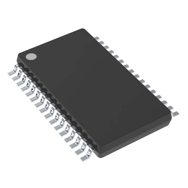
Texas Instruments TPS65381AQDAPTQ1
- Part No.:
- TPS65381AQDAPTQ1
- Manufacturer:
- Texas Instruments
- Category:
- Special Purpose Regulators
- Package:
- 32-PowerTSSOP (0.240", 6.10mm Width)
- Datasheet:
-
 TPS65381AQDAPTQ1.pdf
- Description:
- IC REG AUTOMOTIVE 5OUT 32HTSSOP
- Quantity:
- Payment:

- Shipping:

Inventory:1,907
Please send an inquiry. Send us your inquiry, and we will respond immediately.
Product details
Overview
TPS65381AQDAPTQ1 from Texas Instruments is an AEC-Q100 Grade 1 automotive multirail power supply IC designed to power safety-critical microcontrollers including TI Hercules™ TMS570 and C2000™ families. It integrates a 6-V asynchronous buck preregulator (1.3-A), dual LDOs (5-V/300-mA and 3.3-V/300-mA), adjustable core regulator controller (0.8–3.3 V, external FET), and protected 3.3–9.5-V sensor supply (100-mA) - all in a single 32-pin HTSSOP PowerPAD™ package for EPS, ABS, and ADAS ECUs.
For engineers reviewing the TPS65381AQDAPTQ1 datasheet, TPS65381AQDAPTQ1 pinout, TPS65381AQDAPTQ1 application, or TPS65381AQDAPTQ1 equivalent, this page delivers verified functional specifications, validated pin functions, confirmed safety-monitoring architecture (independent bandgap references, self-check on voltage monitoring), and real-world automotive use context - enabling rapid integration into ISO 26262 ASIL-B/C system designs without speculative interpretation.
Technical Context
The TPS65381AQDAPTQ1 implements a hierarchical power architecture: a 6-V asynchronous buck preregulator (with internal FET and 440-kHz hysteretic PWM control) feeds three downstream linear regulators and a tracking sensor supply. Its safety monitoring subsystem uses a dedicated second bandgap reference for independent undervoltage/overvoltage detection on all rails, battery, and internal supplies - decoupled from the main reference to ensure fault detectability under drift conditions.
It supports dual-mode watchdog (trigger and question-and-answer), MCU error-signal monitoring for lock-step dual-core MCUs, diagnostic state execution with built-in self-test (BIST) at power-up, CRC on nonvolatile registers, and a diagnostic MUX output (DIAG_OUT) that routes internal analog/digital signals to the MCU for external validation - all coordinated through SAFE and DIAGNOSTIC operational states.
Key Specifications
| Parameter | Value and Actual Design Meaning |
|---|---|
| Input Voltage Range | 5.8 V to 36 V (full regulator functionality); 4.5 V to 5.8 V (limited operation with dropout on some rails) |
| VDD6 Buck Output | 6 V ±10% (5.4–6.6 V), 1.3-A max load, 440-kHz switching frequency, 200-mV p-p ripple |
| VDD5 LDO Output | 5.0 V ±20 mV, 300-mA max, 0.3-V dropout, >40 dB PSRR (50 Hz–20 kHz) |
| VDD3/5 LDO Output | Selectable 3.3 V or 5.0 V, ±20 mV accuracy, 300-mA max, 0.3-V dropout |
| VDD1 Core Controller | Adjustable 0.8–3.3 V via external FET and resistor divider, 10–600 mA output capability |
| Sensor Supply (VSOUT1) | 3.3–9.5 V adjustable/tracking mode, 100-mA max, short-to-supply/short-to-ground protection |
| Operating Temperature | –40°C to +125°C ambient (AEC-Q100 Grade 1 qualified) |
| ESD Rating | HBM ±2000 V (all pins except VSOUT1/VSFB1), CDM ±750 V (corner pins) |
Pinout & Package
Package: 32-pin HTSSOP PowerPAD™ (11.00 mm × 6.20 mm), thermally enhanced with exposed thermal pad connected to GND/PGND via vias.
| Pin/Terminal | Circuit Role | Design Meaning |
|---|---|---|
| VBATP (Pin 29) | Main battery input | Primary power source for all regulators; reverse-protected input requiring external diode or NMOS solution |
| VDD6 (Pin 27) | Buck preregulator feedback/supply | Feedback node for 6-V buck; also supplies VDD5, VDD3/5, and VDD1 controller circuitry |
| VDD5 (Pin 20) | CAN/FlexRay transceiver LDO output | Fixed 5-V rail with internal FET; powers CAN transceivers directly with 300-mA capability |
| VDD3/5 (Pin 21) | MCU I/O supply LDO output | Selectable 3.3 V or 5 V via SEL_VDD3/5 pin; 300-mA max, low-noise for digital I/O domains |
| VDD1_G (Pin 26) | External FET gate driver | Drives N-channel MOSFET for adjustable MCU core supply (VDD1); 15-V max gate drive capability |
| DIAG_OUT (Pin 7) | Multiplexed diagnostic output | Allows MCU to observe internal analog (AMUX) and digital (DMUX) signals for interconnect and functional validation |
| NRES (Pin 6) | Cold reset output | Active-low open-drain reset signal to MCU; asserted during UV/OV faults or SAFE state entry |
| ENDRV (Pin 32) | Safing-path enable drive | Open-drain output to disable external motor drivers or safing circuits upon detected system failure |
Key Features
| Feature | Design Value |
|---|---|
| Dual independent bandgap references | One for regulation, one exclusively for voltage monitoring - ensures undetected drift cannot compromise safety-critical UV/OV detection |
| Self-check on voltage monitoring | Automatic verification during power-up and on-demand via MCU command, validating comparator and reference integrity before system release |
| Diagnostic MUX (DIAG_OUT) | Enables MCU ADC and GPIO to sample internal analog (e.g., VDD1_SENSE) and digital (e.g., status flags) signals - critical for ASIL-B/C diagnostic coverage |
| SAFE and DIAGNOSTIC operational states | Hardware-enforced states: SAFE disables outputs and asserts ENDRV/NRES on fault; DIAGNOSTIC enables full BIST and register readback without affecting system operation |
| Charge pump (VCP) | Generates ~12 V above battery for reverse-battery protection (driving external NMOS) and overdrive for internal regulators - extends minimum operating voltage below 5.8 V |
| MCU error-signal monitor | Detects PWM-based error outputs from Hercules™ TMS570 and C2000™ lock-step MCUs - triggers immediate SAFE state transition on mismatch |
Applications
| Power Steering (EPS/EHPS) | Braking Systems (ABS/ESC) |
|---|---|
Use Scenario: Electrical Power Steering module requiring redundant power delivery and real-time fault response to prevent unintended torque. IC Role / Device Role / Timing Role: Primary multirail power manager and safety monitor - supplies MCU core, I/O, CAN, and sensor rails while continuously validating voltage integrity and executing BIST. Use Value: Enables ASIL-C compliance via independent monitoring paths, cold reset assertion within 10 µs of UV event, and hardware SAFE state activation without MCU intervention. |
Use Scenario: Anti-lock Brake System ECU where loss of MCU supply must trigger immediate hydraulic valve isolation. IC Role / Device Role / Timing Role: Safety-critical power supervisor - monitors VDD1 (core), VDD3/5 (I/O), and CAN supply (VDD5) with separate references, asserting ENDRV to cut off motor drivers on fault. Use Value: Guarantees <500-µs fault-to-action latency via hardware SAFE state, eliminating software dependency for fail-safe actuation. |
| ADAS Sensor Fusion Unit | Railway Signal Control |
Use Scenario: Radar + camera fusion ECU needing stable, isolated supplies for high-speed interfaces and analog front-ends. IC Role / Device Role / Timing Role: Integrated power and diagnostics hub - delivers clean 3.3-V I/O, 5-V CAN, and adjustable 1.2-V core while tracking sensor supply (VSOUT1) for radar MMIC bias. Use Value: Short-to-ground protection on VSOUT1 prevents sensor fault propagation; DIAG_OUT allows MCU to validate analog supply health pre-boot. |
Use Scenario: Interlocking logic controller requiring SIL-3 certification and immunity to battery transients in rail yard environments. IC Role / Device Role / Timing Role: Certified safety power IC - provides monitored 5-V logic, 3.3-V communication, and 6-V preregulation with wake-on-IGN/CANWU for low-power standby. Use Value: AEC-Q100 Grade 1 qualification and 125°C operation ensure reliability in uncooled cabinets; charge pump enables operation down to 4.5 V during brownout. |
Equivalent & Alternatives
The following parts are listed as comparable options for similar multirail safety power management applications.
| Alternative Part | Technical Difference | Application Difference | Selection Advice |
|---|---|---|---|
| TPS65381QDAPTQ1 | Non-A version; lacks updated watchdog timing and minor diagnostic register enhancements per SLVSDJ1A revision May 2017 | Acceptable for legacy ASIL-B designs where Q&A watchdog latency tolerance >10 µs and no DIAGNOSTIC state register extensions required | Verify compatibility with existing firmware - TPS65381AQDAPTQ1 adds DIAGNOSTIC state entry via SPI command not present in base Q version. |
| MAX25202ATPA/VY+ | 3-rail automotive PMIC (3.3-V/5-V/adjustable core); no integrated sensor supply or charge pump; different SPI protocol and watchdog implementation | Used in non-safety-critical ADAS cameras; lacks dual-bandgap monitoring, BIST, and SAFE state hardware enforcement | Only suitable for ASIL-A systems; requires redesign of voltage monitoring, reset coordination, and diagnostic MUX interface. |
Compared with TPS65381AQDAPTQ1, the TPS65381QDAPTQ1 offers identical safety architecture but omits post-2017 diagnostic enhancements, while MAX25202ATPA/VY+ provides simpler power sequencing without functional safety features - making TPS65381AQDAPTQ1 uniquely suited for ASIL-B/C MCU power in EPS, braking, and railway control where hardware-enforced SAFE state and independent monitoring are mandatory.
Availability
TPS65381AQDAPTQ1 is available at Aetrix Electronics and suitable for automotive electronic power steering, braking control units, and ADAS sensor modules requiring stable component supply across extended temperature ranges and long production lifecycles.
Supply support for TPS65381AQDAPTQ1 includes scheduled delivery planning, volume procurement assistance, BOM continuity management, traceable sourcing, and lifecycle availability coordination for OEM customers, industrial embedded developers, connected-device designers, and electronics production programs.
Manufacturer
Texas Instruments is a global semiconductor leader specializing in analog, embedded processing, and automotive ICs, with decades of automotive qualification expertise and AEC-Q100-compliant manufacturing.
The TPS65381A-Q1 belongs to TI's functional-safety power management portfolio, engineered specifically for ISO 26262 ASIL-B/C applications in electric power steering, braking, and ADAS - integrating monitoring, diagnostics, and fail-safe response in a single package.
FAQ
What is the primary safety function of the TPS65381AQDAPTQ1 in automotive systems?
The TPS65381AQDAPTQ1 provides hardware-enforced functional safety by continuously monitoring all output rails, battery voltage, and internal supplies using a dedicated second bandgap reference - ensuring undetected drift cannot mask undervoltage or overvoltage faults. It executes built-in self-tests (BIST) at power-up, supports Q&A watchdog protocols for lock-step MCUs, and transitions to a SAFE state that asserts ENDRV and NRES to isolate peripherals and reset the MCU within microseconds of fault detection - meeting ASIL-B/C requirements for EPS and braking systems.
How does the TPS65381AQDAPTQ1 handle low-battery conditions below 5.8 V?
The TPS65381AQDAPTQ1 remains functional down to 4.5 V on VBATP after initial power-up, maintaining regulated outputs where possible: VDD6 operates in 100% duty-cycle dropout mode, VDD3/5 (3.3-V setting) stays active, and VDD5/VSOUT1 indicate undervoltage via status bits without forcing RESET. Its integrated charge pump generates ~12 V above battery to drive external reverse-battery NMOS, enabling operation at lower voltages than diode-based solutions - critical for cold-crank scenarios in automotive applications.
Can the TPS65381AQDAPTQ1 supply both Hercules™ TMS570 and C2000™ microcontrollers simultaneously?
Yes, the TPS65381AQDAPTQ1 is explicitly designed to support TI's Hercules™ TMS570 and C2000™ MCU families, providing all required rails: adjustable 0.8–3.3 V core supply (VDD1) via external FET, selectable 3.3-V/5-V I/O supply (VDD3/5), 5-V CAN transceiver supply (VDD5), and 6-V preregulator (VDD6). Its MCU error-signal monitor detects PWM-based fault outputs from both MCU families, and its DIAGNOSTIC state allows full validation of monitoring functions prior to system release - confirmed in TI's SLVSDJ1A datasheet Section 1.3.
What is the role of the DIAG_OUT pin on the TPS65381AQDAPTQ1?
The DIAG_OUT pin on the TPS65381AQDAPTQ1 is a multiplexed diagnostic output that routes internal analog signals (e.g., VDD1_SENSE, VMON references) and digital signals (e.g., status flags, watchdog states) to the MCU's ADC or GPIO pins. This enables external validation of internal health - such as verifying reference stability or confirming voltage monitor thresholds - without requiring additional test points. It is actively used during the DIAGNOSTIC state to support ASIL-B/C diagnostic coverage requirements per ISO 26262.
Does the TPS65381AQDAPTQ1 require external components for its sensor supply (VSOUT1)?
Yes, the VSOUT1 sensor supply requires external configuration: for tracking mode, VSOUT1 connects directly to VSFB1 or through a resistor divider referenced to VTRACK1; for adjustable mode, a resistor divider sets the output between 3.3 V and 9.5 V. The device integrates short-to-ground and short-to-supply protection internally, but external capacitors (CVSOUT1 ≥ 1 µF, low-ESR) are mandatory for stability and transient response - specified in TI's SLVSDJ1A datasheet Section 4.5 and Figure 1-1 typical application diagram.
TPS65381AQDAPTQ1 Specifications
- Product attributes
- Attribute value
- Manufacturer:
- Texas Instruments
- Series:
- Functional Safety (FuSa)
- Package/Case:
- 32-PowerTSSOP (0.240", 6.10mm Width)
- Packaging:
- Tape & Reel (TR)
- Product Status:
- Active
- Applications:
- Industrial Safety
- Voltage - Input:
- 4.5V ~ 36V
- Number of Outputs:
- 5
- Voltage - Output:
- Multiple
- Operating Temperature:
- -40°C ~ 125°C
- Grade:
- Automotive
- Qualification:
- AEC-Q100
- Mounting Type:
- Surface Mount
- Supplier Device Package:
- 32-HTSSOP
TPS65381AQDAPTQ1 FAQ
1.How can I place an order for TPS65381AQDAPTQ1 through Aetrix?
Please submit a Request for Quotation (RFQ) for TPS65381AQDAPTQ1 on Aetrix. Our sales agent will provide a competitive quotation and guide you through the order confirmation once you accept the terms.
2.Are the price and stock information for TPS65381AQDAPTQ1 reliable?
The price and inventory of TPS65381AQDAPTQ1 are updated periodically and may fluctuate due to market conditions. Stock and pricing data are typically refreshed every 24 hours. Quotation validity for TPS65381AQDAPTQ1 is usually 5 days.
3.What payment methods are accepted for TPS65381AQDAPTQ1?
We accept Wire Transfer, PayPal, Credit Card, Western Union, MoneyGram, and Escrow for TPS65381AQDAPTQ1 transactions.
Note: Certain payment methods may incur a processing fee.
4.How is shipping managed for TPS65381AQDAPTQ1?
TPS65381AQDAPTQ1 orders can be shipped via leading logistics carriers, including DHL, UPS, FedEx, TNT, or Registered Mail.
Once your TPS65381AQDAPTQ1 order is processed, you will receive an email with the shipment details and tracking number.
Note: Tracking information may take up to 24 hours to appear. Express delivery typically takes 3–5 business days.
5.How can I obtain technical support or documentation for TPS65381AQDAPTQ1?
For technical support, including TPS65381AQDAPTQ1 datasheets, pinout diagrams, or application guidance, please contact our engineering support team. They can provide detailed documentation and assistance for your TPS65381AQDAPTQ1 requirements.
6.How does Aetrix verify that TPS65381AQDAPTQ1 is sourced from the original manufacturer or authorized distributors?
All TPS65381AQDAPTQ1 products on Aetrix are procured from qualified distributors and authorized channels. Our dedicated quality assurance team conducts strict verification, including traceability checks and, if necessary, third-party testing. This ensures that TPS65381AQDAPTQ1 meets industry standards.
7.What is the process for return or replacement of TPS65381AQDAPTQ1?
All TPS65381AQDAPTQ1 units undergo pre-shipment inspection (PSI). If there is an issue with TPS65381AQDAPTQ1, returns or replacements are accepted under the following conditions:
1.Quantity discrepancies, incorrect items, or visible external defects (such as breakage or corrosion), acknowledged by Aetrix.
2.The issue is reported within 90 days of delivery.
3.The TPS65381AQDAPTQ1 part is unused and in its original packaging.
Return procedure for TPS65381AQDAPTQ1:
1.Submit a request within 90 days.
2.Obtain a Return Material Authorization (RMA) from Aetrix.
TPS65381AQDAPTQ1 Tags

-
TPS51206DSQR
Texas Instruments

-
TPS51200DRCR
Texas Instruments
-
TPS51200DRCT
Texas Instruments

-
TPS62740DSSR
Texas Instruments

-
TPS51100DGQR
Texas Instruments

-
NCP51200MNTXG
onsemi
-
NCP51400MNTXG
onsemi

-
RT9026GSP
Richtek USA Inc.

-
LP2998MRX/NOPB
Texas Instruments
-
TPS51200QDRCRQ1
Texas Instruments

-
DPA423GN-TL
Power Integrations
-
LM10011SD/NOPB
Texas Instruments
Tech Hub

A practical engineering guide to 3.3V and 5V logic compatibility, input thresholds, resistor dividers, translator ICs, MOSFET level shifting, I2C pull-ups, timing limits and power-sequencing risks.

The 74HC595 uses push-pull logic outputs, while the TPIC6B595 uses 50 V open-drain DMOS sinks for higher-power loads. This guide compares timing, current limits, 3.3 V interfacing, load wiring, thermal…

The 74HC595 converts serial data into eight stable parallel outputs. This guide covers pin functions, shift and storage timing, OE and MR behavior, drive-current limits, cascading, voltage compatibilit…

A technical comparison of level-sensitive latches and edge-triggered flip-flops, covering timing windows, setup and hold limits, master–slave operation, time borrowing, race-through, HDL inference and…

A D latch stores one bit while Enable controls when data can pass. This reference covers gate-level operation, truth tables, transparency, setup and hold timing, LE versus OE, common ICs and practical …

An SR latch stores one bit through cross-coupled feedback. This engineering reference covers NOR and NAND implementations, truth tables, forbidden-state recovery, gated operation, switch debouncing, fa…

Latch circuits retain one bit through feedback. This technical reference covers SR and D latches, truth tables, transparency, timing limits, latch-versus-flip-flop behavior, applications and common log…

An engineering guide to LED driver operation, constant-current and constant-voltage outputs, linear and switching topologies, dimming, IC selection, calculations, replacement compatibility, and fault c…

Operational amplifier guide covering op amp basics, feedback, ideal vs real op amps, common configurations, buffer circuits, offset, bias current, gain-bandwidth, slew rate, rail-to-rail limits and sel…

Jumper cables guide covering safe connection order, red and black clamp placement, final ground connection, cable gauge, length, clamp quality, copper vs CCA cables, jump starter comparison and battery…


