
 My Inquiry
 My Account


Texas Instruments TS3V713ELRTGR
- Part No.:
- TS3V713ELRTGR
- Manufacturer:
- Texas Instruments
- Category:
- Analog Switches - Special Purpose
- Package:
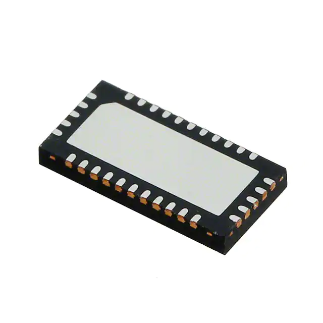
- 32-WFQFN Exposed Pad
- Datasheet:
-
 TS3V713ELRTGR.pdf
- Description:
- IC MUX/DEMUX VIDEO SW 7CH 32WQFN
- Quantity:
- Payment:

- Shipping:

Inventory:4,531
Please send an inquiry. Send us your inquiry, and we will respond immediately.
Product details
Overview
TS3V713ELRTGR from Texas Instruments is a 7-channel, 1:2 VGA video multiplexer/demultiplexer with integrated level shifters and clamping NMOS switches. It supports R/G/B/HSYNC/VSYNC/DDC_CLK/DDC_DAT signals, delivers 1.3 GHz bandwidth (–3 dB), 4 Ω typical RON for RGB channels, and operates at VDD = 3.3 V ±10% and VDD_5 = 5 V ±10%. It is used in notebook computers and docking stations to route VGA signals between one source and two display endpoints without signal degradation.
For engineers reviewing the TS3V713ELRTGR datasheet, TS3V713ELRTGR pinout, TS3V713ELRTGR application, or TS3V713ELRTGR equivalent, key selection considerations include its dual-supply operation (3.3 V + 5 V), integrated HSYNC/VSYNC level shifting, SCL/SDA voltage clamping, ESD robustness (±2 kV contact), and QFN-32 package with exposed thermal pad tied to GND.
Technical Context
The TS3V713ELRTGR implements three distinct switching domains: (1) low-RON analog switches for R/G/B paths (4 Ω typ., 1.3 GHz BW); (2) level-shifting buffers for HSYNC/VSYNC translating between 3.3 V and 5 V logic; and (3) NMOS clamping switches for SCL/SDA lines limiting output to VDD – 1 V. All analog I/Os feature integrated ESD diodes to VDD and GND.
Control is managed via a single SEL pin enabling either output bank (Bank 1 or Bank 2). Propagation delay is ≤0.25 ns for RGB/SDA/SCL paths and ≤7 ns for HSYNC/VSYNC paths; output skew is ≤0.1 ns between RGB channels. The device requires both VDD (3.3 V) and VDD_5 (5 V) supplies and mandates GND connection of the exposed center pad.
Key Specifications
| Parameter | Value and Actual Design Meaning |
|---|---|
| Bandwidth | 1.3 GHz (–3 dB) - preserves VGA signal integrity up to UXGA (1600×1200) timing |
| R/G/B ON-resistance | 4 Ω typ. - minimizes insertion loss and impedance mismatch in 75-Ω VGA paths |
| R/G/B OFF-isolation | –40 dB at 250 MHz - prevents crosstalk between active and inactive video channels |
| HSYNC/VSYNC level shift | 3.3 V ↔ 5 V bidirectional translation - enables interoperability between GPU and monitor DDC logic |
| SCL/SDA clamp voltage | VDD – 1 V - protects I²C bus from overvoltage while maintaining SMBus compatibility |
| ESD rating (DDC pins) | ±2 kV contact discharge (IEC61000-4-2) - meets industrial-grade interface robustness requirements |
| Supply voltages | VDD = 3.3 V ±10%, VDD_5 = 5 V ±10% - separates analog switch core from level-shifter domain |
Pinout & Package
TS3V713ELRTGR uses a 32-pin WQFN (RTG) package with 5 mm × 5 mm body, 0.5 mm pitch, and an exposed thermal pad that must be soldered to GND for thermal and EMI performance.
| Pin/Terminal | Circuit Role | Design Meaning |
|---|---|---|
| 1–6, 9–11, 16, 28–32 | R0/G0/B0/H0/V0/SDA0/SCL0, R1/G1/B1/H1/V1/SDA1/SCL1, R2/G2/B2/H2/V2/SDA2/SCL2 | Three banks of 7-channel VGA I/O: Bank 0 (input), Bank 1 & Bank 2 (outputs); SDA/SCL use clamping NMOS, H/V use level-shift buffers |
| 7, 8, 12–15, 17–22, 24–27 | GND (multiple) | Dedicated ground connections per functional block; exposed pad must be connected to GND plane |
| 19, 23, 25 | VDD | 3.3 V supply for RGB switches and digital control logic |
| 20, 26 | VDD_5 | 5 V supply dedicated to HSYNC/VSYNC level-shifting buffers |
| 29 | SEL | Single digital select input: low → route to Bank 1; high → route to Bank 2 |
Key Features
| Feature | Design Value |
|---|---|
| Integrated HSYNC/VSYNC level shifters | Eliminates external level translators in VGA DDC path, reducing BOM count and board area |
| Voltage-clamped SCL/SDA switches | Ensures I²C outputs never exceed VDD – 1 V, preventing damage to 3.3 V monitor-side controllers |
| Low 4 Ω RGB RON with flatness ≤1 Ω | Maintains consistent 75 Ω impedance matching across full video swing (0–0.7 V), minimizing ghosting |
| 1.3 GHz analog bandwidth | Supports pixel clocks up to 162 MHz (UXGA @ 60 Hz), exceeding standard VGA timing requirements |
| ±2 kV IEC61000-4-2 ESD on DDC pins | Enables direct front-panel VGA connector routing without external TVS diodes |
Applications
| Notebook Computers | Docking Stations |
|---|---|
Use Scenario: Switching internal GPU output between built-in LCD and external VGA port based on lid-open/closed or user command. IC Role / Device Role / Timing Role: VGA multiplexer handling all seven VGA signals (R/G/B/HSYNC/VSYNC/DDC_CLK/DDC_DAT) with sub-ns propagation delay. Use Value: Enables seamless hot-plug detection and display enumeration via intact DDC channel routing without level-shifter or buffer ICs. | Use Scenario: Routing a single laptop's VGA output to multiple monitors or projectors through a shared docking hub. IC Role / Device Role / Timing Role: Dual-output demultiplexer selecting between two downstream VGA endpoints using SEL pin under host GPIO control. Use Value: Maintains full-bandwidth video fidelity across both outputs with <0.1 ns RGB skew, eliminating visible timing artifacts. |
| KVM Switches | Industrial Display Controllers |
Use Scenario: Sharing one VGA monitor among multiple PCs via manual or software-controlled KVM matrix. IC Role / Device Role / Timing Role: Bidirectional 1:2 video switch supporting upstream DDC readback for EDID passthrough and automatic resolution negotiation. Use Value: Integrated level shifters preserve DDC communication across mixed-voltage systems (e.g., 3.3 V GPU ↔ 5 V monitor), avoiding handshake failures. | Use Scenario: Integrating VGA output into ruggedized human-machine interface (HMI) panels requiring ESD-hardened video routing. IC Role / Device Role / Timing Role: Robust VGA signal conditioner with ±2 kV contact ESD protection on all DDC and sync lines. Use Value: Eliminates need for discrete ESD protection components on VGA interface PCB, improving reliability in factory-floor environments. |
Equivalent & Alternatives
The following parts are listed as comparable options for similar VGA video switching applications.
| Alternative Part | Technical Difference | Application Difference | Selection Advice |
|---|---|---|---|
| TS3V712ELRTGR | 6-channel version (no VSYNC path); identical bandwidth, RON, and package | Omits VSYNC line - insufficient for full VGA compliance where VSYNC is required for EDID/DPMS | Select only if VSYNC is unused or handled separately in system design |
| PI3USB30532ZLEX | USB 3.0/PCIe switch with 1.2 GHz BW; no integrated level shifters or DDC clamping | Designed for high-speed serial data, not analog RGB; requires external level translation for VGA DDC | Not suitable as drop-in replacement; only consider for new designs targeting USB-C Alt Mode video |
Compared with TS3V713ELRTGR, TS3V712ELRTGR lacks VSYNC support and thus cannot fully replace it in VGA applications requiring DPMS or EDID handshake, while PI3USB30532ZLEX targets digital protocols and offers no native VGA signal conditioning or DDC protection.
Availability
TS3V713ELRTGR is available at Aetrix Electronics and suitable for notebook computers, docking stations, and KVM switches requiring stable component supply, long-term industrial lifecycle support, and guaranteed RoHS-compliant WQFN packaging.
Supply support for TS3V713ELRTGR includes scheduled delivery planning, volume procurement assistance, BOM continuity management, traceable sourcing, and lifecycle availability coordination for OEM customers, industrial embedded developers, connected-device designers, and electronics production programs.
Manufacturer
Texas Instruments is a global semiconductor company specializing in analog, embedded processing, and connectivity technologies with decades of leadership in interface and signal-path ICs.
The TS3V713ELRTGR belongs to TI's video interface switch product line, engineered specifically for high-fidelity analog video routing in portable and docked computing systems with integrated DDC signal conditioning.
FAQ
What is the function of the VDD_5 supply pin on the TS3V713ELRTGR?
The VDD_5 pin supplies 5 V to the integrated level-shifting buffers for HSYNC and VSYNC signals, enabling bidirectional voltage translation between 3.3 V GPU logic and 5 V monitor-side DDC circuitry. It is electrically isolated from the 3.3 V VDD rail powering the RGB switches and digital control logic. Proper decoupling (e.g., 0.1 µF ceramic) is required at the VDD_5 pin to maintain level-shifter stability. TS3V713ELRTGR will not operate correctly if VDD_5 is omitted or shorted to VDD.
Can the TS3V713ELRTGR support hot-plug detection via DDC when used in a docking station?
Yes, the TS3V713ELRTGR supports full DDC hot-plug detection by passing SDA0/SCL0 bidirectionally to either SDA1/SCL1 or SDA2/SCL2 with integrated clamping (output limited to VDD – 1 V) and ±2 kV IEC61000-4-2 ESD protection. This preserves I²C waveform integrity during cable insertion/removal. The TS3V713ELRTGR maintains DC coupling and low capacitance (<8.2 pF) on DDC lines, ensuring reliable EDID reads and monitor enumeration without external repeaters or translators.
What is the maximum recommended trace length for RGB signals routed through the TS3V713ELRTGR?
For optimal signal integrity at 1.3 GHz bandwidth, RGB traces should be impedance-controlled at 75 Ω with length ≤10 cm (4 inches) from TS3V713ELRTGR output pins to the VGA connector. Longer traces increase insertion loss and crosstalk risk; simulation or TDR validation is advised beyond this length. The TS3V713ELRTGR's 4 Ω RON and 8 pF CON minimize loading effects, but PCB layout remains critical-avoid vias near analog pins and use solid GND planes beneath the WQFN thermal pad.
Does the TS3V713ELRTGR require external pull-up resistors on SCL/SDA lines?
No, external pull-ups are not required on SCL/SDA lines driven by the TS3V713ELRTGR because its NMOS switches provide active clamping to VDD – 1 V and rely on the monitor-side or GPU-side pull-ups already present in standard VGA implementations. Adding external pull-ups may cause contention or violate the VDD – 1 V clamp limit. The TS3V713ELRTGR datasheet specifies that SCL/SDA pins are designed to interface directly with compliant I²C masters/slaves without additional biasing components.
How does the TS3V713ELRTGR handle simultaneous switching of multiple video channels?
TS3V713ELRTGR switches all seven channels (R/G/B/HSYNC/VSYNC/DDC_CLK/DDC_DAT) simultaneously under a single SEL control signal, with propagation delays matched to ≤0.1 ns skew between RGB paths and ≤7 ns for H/V paths. This ensures pixel-aligned timing across the entire VGA signal set. The device's monolithic construction and shared substrate eliminate inter-channel timing drift, making TS3V713ELRTGR suitable for high-resolution, flicker-free video routing where phase coherence is critical.
TS3V713ELRTGR Specifications
- Product attributes
- Attribute value
- Manufacturer:
- Texas Instruments
- Series:
- -
- Package/Case:
- 32-WFQFN Exposed Pad
- Packaging:
- Tape & Reel (TR)
- Product Status:
- Active
- Applications:
- Video
- Multiplexer/Demultiplexer Circuit:
- 2:1
- Switch Circuit:
- SPDT
- Number of Channels:
- 7
- On-State Resistance (Max):
- 8Ohm
- Voltage - Supply, Single (V+):
- 3V ~ 3.6V, 4.5V ~ 5.5V
- Voltage - Supply, Dual (V±):
- -
- -3db Bandwidth:
- 1.3GHz
- Features:
- DDC CLK, DDC DAT, HSYNC, RGB, VSYNC
- Operating Temperature:
- -40°C ~ 85°C (TA)
- Grade:
- -
- Qualification:
- -
- Mounting Type:
- Surface Mount
- Supplier Device Package:
- 32-WQFN (6x3)
TS3V713ELRTGR FAQ
1.How can I place an order for TS3V713ELRTGR through Aetrix?
Please submit a Request for Quotation (RFQ) for TS3V713ELRTGR on Aetrix. Our sales agent will provide a competitive quotation and guide you through the order confirmation once you accept the terms.
2.Are the price and stock information for TS3V713ELRTGR reliable?
The price and inventory of TS3V713ELRTGR are updated periodically and may fluctuate due to market conditions. Stock and pricing data are typically refreshed every 24 hours. Quotation validity for TS3V713ELRTGR is usually 5 days.
3.What payment methods are accepted for TS3V713ELRTGR?
We accept Wire Transfer, PayPal, Credit Card, Western Union, MoneyGram, and Escrow for TS3V713ELRTGR transactions.
Note: Certain payment methods may incur a processing fee.
4.How is shipping managed for TS3V713ELRTGR?
TS3V713ELRTGR orders can be shipped via leading logistics carriers, including DHL, UPS, FedEx, TNT, or Registered Mail.
Once your TS3V713ELRTGR order is processed, you will receive an email with the shipment details and tracking number.
Note: Tracking information may take up to 24 hours to appear. Express delivery typically takes 3–5 business days.
5.How can I obtain technical support or documentation for TS3V713ELRTGR?
For technical support, including TS3V713ELRTGR datasheets, pinout diagrams, or application guidance, please contact our engineering support team. They can provide detailed documentation and assistance for your TS3V713ELRTGR requirements.
6.How does Aetrix verify that TS3V713ELRTGR is sourced from the original manufacturer or authorized distributors?
All TS3V713ELRTGR products on Aetrix are procured from qualified distributors and authorized channels. Our dedicated quality assurance team conducts strict verification, including traceability checks and, if necessary, third-party testing. This ensures that TS3V713ELRTGR meets industry standards.
7.What is the process for return or replacement of TS3V713ELRTGR?
All TS3V713ELRTGR units undergo pre-shipment inspection (PSI). If there is an issue with TS3V713ELRTGR, returns or replacements are accepted under the following conditions:
1.Quantity discrepancies, incorrect items, or visible external defects (such as breakage or corrosion), acknowledged by Aetrix.
2.The issue is reported within 90 days of delivery.
3.The TS3V713ELRTGR part is unused and in its original packaging.
Return procedure for TS3V713ELRTGR:
1.Submit a request within 90 days.
2.Obtain a Return Material Authorization (RMA) from Aetrix.
TS3V713ELRTGR Tags
-
TS3USB221ARSER
Texas Instruments
-
TS3USB221AQRSERQ1
Texas Instruments
-
NX3DV221GM,115
NXP Semiconductors
-
NX3DV2567GU,115
NXP Semiconductors
-
TS3USB221RSER
Texas Instruments
-
TS3USB221ERSER
Texas Instruments
-
TC7USB40MU,LF(S2E
Toshiba Semiconductor and Storage

-
TS3USB30EDGSR
Texas Instruments
-
PI3USB221AZUAEX
Diodes Incorporated
-
FSUSB42UMX
onsemi
-
CBTL01023GM,115
NXP Semiconductors
-
TS3USB30ERSWR
Texas Instruments
Tech Hub

A practical engineering guide to 3.3V and 5V logic compatibility, input thresholds, resistor dividers, translator ICs, MOSFET level shifting, I2C pull-ups, timing limits and power-sequencing risks.

The 74HC595 uses push-pull logic outputs, while the TPIC6B595 uses 50 V open-drain DMOS sinks for higher-power loads. This guide compares timing, current limits, 3.3 V interfacing, load wiring, thermal…

The 74HC595 converts serial data into eight stable parallel outputs. This guide covers pin functions, shift and storage timing, OE and MR behavior, drive-current limits, cascading, voltage compatibilit…

A technical comparison of level-sensitive latches and edge-triggered flip-flops, covering timing windows, setup and hold limits, master–slave operation, time borrowing, race-through, HDL inference and…

A D latch stores one bit while Enable controls when data can pass. This reference covers gate-level operation, truth tables, transparency, setup and hold timing, LE versus OE, common ICs and practical …

An SR latch stores one bit through cross-coupled feedback. This engineering reference covers NOR and NAND implementations, truth tables, forbidden-state recovery, gated operation, switch debouncing, fa…

Latch circuits retain one bit through feedback. This technical reference covers SR and D latches, truth tables, transparency, timing limits, latch-versus-flip-flop behavior, applications and common log…

An engineering guide to LED driver operation, constant-current and constant-voltage outputs, linear and switching topologies, dimming, IC selection, calculations, replacement compatibility, and fault c…

Operational amplifier guide covering op amp basics, feedback, ideal vs real op amps, common configurations, buffer circuits, offset, bias current, gain-bandwidth, slew rate, rail-to-rail limits and sel…

Jumper cables guide covering safe connection order, red and black clamp placement, final ground connection, cable gauge, length, clamp quality, copper vs CCA cables, jump starter comparison and battery…


