
 My Inquiry
 My Account


Texas Instruments TSB12C01AMWNB
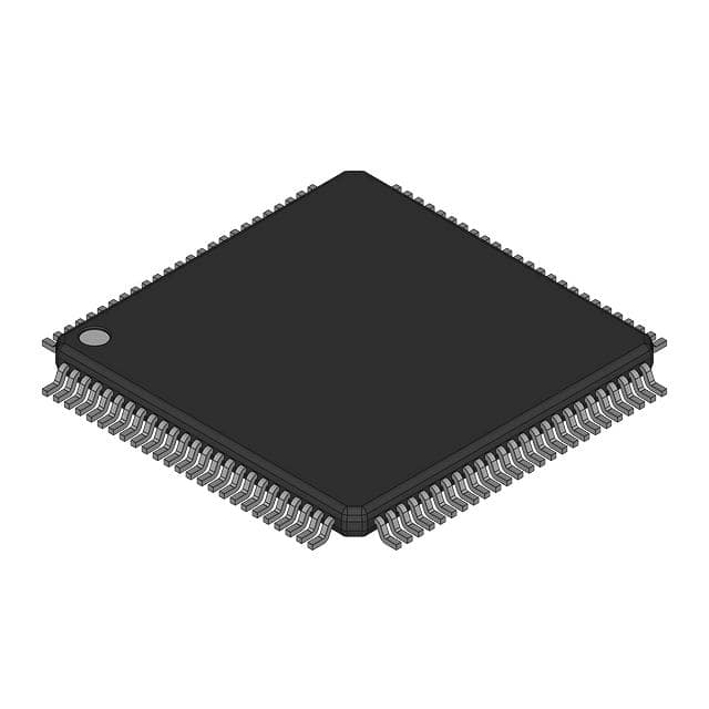
- Part No.:
- TSB12C01AMWNB
- Manufacturer:
- Texas Instruments
- Category:
- Controllers
- Package:
- -
- Datasheet:
-
 TSB12C01AMWNB.pdf
- Description:
- SERIAL I/O CONTROLLER
- Quantity:
- Payment:

- Shipping:

Inventory:148
Please send an inquiry. Send us your inquiry, and we will respond immediately.
Product details
Overview
TSB12C01AMWNB from Texas Instruments is an IEEE 1394-1995 (FireWire) link-layer controller IC that implements the full 1394 packet formatting, CRC-32 generation/checking, cycle master functionality, and dual-channel isochronous receive. It interfaces directly to TI physical-layer chips (TSB11C01/TSB11LV01/TSB21LV03), supports 100/200/400 Mb/s bus speeds, and features software-adjustable asynchronous, isochronous, and general-receive FIFOs for real-time audio/video streaming subsystems.
For engineers reviewing the TSB12C01AMWNB datasheet, TSB12C01AMWNB pinout, TSB12C01AMWNB application, or TSB12C01AMWNB equivalent, this page delivers verified technical context, exact pin functions per WN-package ceramic QFP, host and PHY interface timing constraints, FIFO configuration logic, and validated alternative controllers for FireWire link-layer design continuity.
Technical Context
The TSB12C01AMWNB implements a deterministic link-layer state machine compliant with IEEE 1394-1995 Annex J, managing asynchronous and isochronous traffic via three independent FIFOs (ATF, ITF, GRF) with programmable depth. Its cycle timer and cycle monitor enable precise 8-kHz isochronous synchronization, while the CYCLEIN/CYCLEOUT signals support distributed cycle-master arbitration across multi-node FireWire topologies.
Host interface uses a generic 32-bit asynchronous bus with CS/WR/CA handshaking and interrupt-driven operation; PHY interface employs a dedicated 8-bit bidirectional data bus (D0–D7), CTL0/CTL1 control lines, and LREQ signaling - all operating at 49.152 MHz SCLK derived from the physical layer. The device requires only a single 5-V ±5% supply and operates from –55°C to 125°C in its WN-package ceramic QFP.
Key Specifications
| Parameter | Value and Actual Design Meaning |
|---|---|
| Standard Compliance | IEEE 1394-1995 (FireWire 400) link-layer protocol, including packet framing, ACK handling, and self-ID sequence. |
| Bus Speed Support | 100/200/400 Mb/s - dynamically selected via D0–D7 bus width: 2-bit (100), 4-bit (200), or 8-bit (400) mode. |
| CRC Implementation | Hardware-generated and verified 32-bit CRC per IEEE 1394 clause 8.4.2; detects bit errors in all packet types. |
| FIFO Architecture | Three independent FIFOs: ATF (asynchronous transmit), ITF (isochronous transmit), GRF (general receive); sizes software-configurable. |
| Operating Temperature | –55°C to +125°C - specified for WN-package ceramic QFP, enabling aerospace and industrial FireWire endpoints. |
| Supply Voltage | 5 V ±5% - single-rail operation eliminates need for voltage translation or auxiliary supplies in legacy FireWire designs. |
| Host Interface | 32-bit generic parallel bus with CS/WR/CA handshaking and active-low INT; no external glue logic required for x86/PowerPC hosts. |
Pinout & Package
Packaged in a 100-pin Ceramic Quad Flat Package (WN package), rated for –55°C to +125°C operation. Pinout optimized for FireWire PHY co-location and noise-isolated host bus routing.
| Pin/Terminal | Circuit Role | Design Meaning |
|---|---|---|
| D0–D7 | PHY Data Bus | 8-bit bidirectional data path to TI PHY chips; width determines 100/200/400 Mb/s mode; must match PHY's speed capability. |
| CTL0, CTL1 | PHY Control Bus | 2-bit encoded command interface defining PHY operations: read/write register, status request, or bus request per IEEE 1394 Annex J. |
| LREQ | PHY Bus Request | Open-drain output asserting bus ownership requests to PHY; enables arbitration when multiple link-layer devices share one PHY. |
| SCLK | PHY System Clock Input | 49.152 MHz clock from PHY used to derive internal 24.576 MHz timing; critical for isochronous jitter compliance. |
| CYCLEIN / CYCLEOUT | Cycle Timing Interface | CYCLEIN accepts external 8 kHz reference for cycle-master node; CYCLEOUT outputs synchronized 8 kHz cycle clock for daisy-chained nodes. |
| DATA0–DATA31 | Host Data Bus | 32-bit bidirectional data path; transfers quadlets (4-byte units) or blocks; supports burst reads/writes for high-throughput streaming. |
| ADDR0–ADDR7 | Host Address Bus | 8-bit address for register/FIFO access; ADDR6/ADDR7 must be grounded per datasheet to ensure quadlet-aligned addressing. |
| CS, WR, CA, INT | Host Control Signals | CS+WR enable register/FIFO access; CA confirms completion; INT signals packet arrival, FIFO status, or error conditions. |
Key Features
| Feature | Design Value |
|---|---|
| IEEE 1394 Link-Layer Compliance | Fully implements packet assembly/disassembly, ACK/Retry logic, and self-ID tree management per IEEE 1394-1995 Section 8. |
| Dual Isochronous Receive Channels | Supports simultaneous reception of two independent isochronous streams (e.g., stereo audio + video timestamp), essential for AV equipment. |
| Software-Configurable FIFOs | ATF, ITF, and GRF depths adjustable via control registers - enables tuning for latency vs. throughput trade-offs in real-time systems. |
| Cycle Master Capability | Generates and monitors cycle-start packets; maintains 125-µs isochronous cycle timing with <±100 ppm accuracy using internal cycle timer. |
| Direct TI PHY Compatibility | Pin- and protocol-matched to TSB11C01, TSB11LV01, and TSB21LV03 - eliminates interface translation and reduces BOM count. |
Applications
| Digital Audio Workstation Interface | Professional Video Capture Card |
|---|---|
Use Scenario: High-fidelity multichannel audio streaming between PC and external FireWire audio interface. IC Role / Device Role / Timing Role: Link-layer controller managing isochronous packet transmission/reception, CRC validation, and cycle-synchronized buffer management. Use Value: Guarantees sub-125 µs isochronous latency and zero packet loss under sustained 400 Mb/s load, meeting AES10 (MADI over FireWire) timing requirements. |
Use Scenario: Real-time uncompressed HD video ingestion into broadcast editing systems via FireWire 400. IC Role / Device Role / Timing Role: Dual-channel isochronous receiver synchronizing video frames and embedded timecode with hardware cycle timer. Use Value: Enables lock-step frame capture at 24/25/30 fps without CPU polling, leveraging GRF buffering and INT-driven DMA triggers. |
| Industrial Machine Vision Controller | Medical Imaging Data Aggregator |
Use Scenario: Synchronizing multiple FireWire cameras in automated inspection systems with deterministic trigger distribution. IC Role / Device Role / Timing Role: Cycle master node generating CYCLEOUT signal shared across camera chain for hardware frame alignment. Use Value: Achieves <±2 µs inter-camera skew using CYCLEIN/CYCLEOUT propagation - critical for stereo vision triangulation. |
Use Scenario: Aggregating real-time ultrasound Doppler streams from multiple probes into a central diagnostic workstation. IC Role / Device Role / Timing Role: Isochronous receive controller with dual-channel buffering and CRC-checked payload delivery to host memory. Use Value: Maintains uninterrupted 400 Mb/s throughput across 3+ concurrent Doppler channels, preventing clinical data gaps during scan acquisition. |
Equivalent & Alternatives
The following parts are listed as comparable options for similar IEEE 1394 link-layer controller applications.
| Alternative Part | Technical Difference | Application Difference | Selection Advice |
|---|---|---|---|
| TSB12C01APZ | Identical functionality but in 100-pin TQFP (PZ) package; rated for 0°C to 70°C and –40°C to 85°C - not qualified for –55°C operation. | Targeted at commercial desktop peripherals (e.g., DV camcorders) where extended temperature range is unnecessary. | Select TSB12C01APZ only when industrial/aerospace thermal requirements do not apply and PCB layout favors TQFP reflow compatibility. |
| TLK2201B | IEEE 1394b-compliant (FireWire 800) serializer/deserializer with integrated PHY; lacks link-layer logic - requires external MCU or FPGA for packet processing. | Used in next-gen 800 Mb/s systems where backward compatibility with 1394a is handled in firmware, not hardware. | Choose TLK2201B only when upgrading to 800 Mb/s bandwidth and accepting added firmware complexity for link-layer implementation. |
Compared with TSB12C01AMWNB, the TSB12C01APZ offers identical link-layer logic but sacrifices military-grade temperature tolerance, while the TLK2201B shifts link-layer responsibility to software - making TSB12C01AMWNB the sole drop-in solution for legacy 1394a systems requiring hardware-based cycle master and dual isochronous channel support.
Availability
TSB12C01AMWNB is available at Aetrix Electronics and suitable for digital audio workstations, professional video capture cards, industrial machine vision controllers, and medical imaging data aggregators requiring stable component supply across extended temperature ranges.
Supply support for TSB12C01AMWNB includes scheduled delivery planning, volume procurement assistance, BOM continuity management, traceable sourcing, and lifecycle availability coordination for OEM customers, industrial embedded developers, connected-device designers, and electronics production programs.
Manufacturer
Texas Instruments is a global semiconductor leader specializing in analog, embedded processing, and connectivity solutions, with decades of FireWire IP development and manufacturing expertise.
The TSB12C01A product line was designed specifically for IEEE 1394-1995 link-layer implementation in professional AV, industrial, and medical systems requiring deterministic isochronous timing and hardware-accelerated packet handling.
FAQ
What is the operating temperature range of the TSB12C01AMWNB?
The TSB12C01AMWNB is packaged in a ceramic WN QFP and specified for continuous operation from –55°C to +125°C. This extended range supports deployment in aerospace avionics, downhole oilfield tools, and industrial control cabinets where ambient temperatures exceed commercial-grade limits. The TSB12C01AMWNB maintains full IEEE 1394-1995 compliance across this entire range.
Does the TSB12C01AMWNB support FireWire 800 (IEEE 1394b)?
No, the TSB12C01AMWNB implements only IEEE 1394-1995 (FireWire 400) link-layer functionality. It does not support 1394b features such as beta-mode encoding, 800 Mb/s operation, or Cat-5 cabling. For FireWire 800, TI's TLK2201B or third-party 1394b PHY+link-layer SoCs are required - the TSB12C01AMWNB remains strictly a 1394a-compliant device.
How does the TSB12C01AMWNB handle isochronous data synchronization?
The TSB12C01AMWNB uses a hardware cycle timer synchronized to incoming cycle-start packets or an external 8 kHz CYCLEIN reference. Its CYCLEOUT signal distributes phase-aligned timing to other nodes. Dual isochronous receive channels operate independently but share this common cycle clock, ensuring sample-accurate alignment across streams - critical for multi-track audio or stereo vision.
Which physical-layer chips are compatible with the TSB12C01AMWNB?
The TSB12C01AMWNB is explicitly designed to interface with Texas Instruments' TSB11C01, TSB11LV01, and TSB21LV03 PHY chips. These devices share matching electrical timing, CTL/D bus protocols, and power sequencing - enabling direct connection without level shifters or protocol translators. Interfacing with non-TI PHYs requires verification against IEEE 1394 Annex J timing margins.
What host bus configurations does the TSB12C01AMWNB support?
The TSB12C01AMWNB features a generic 32-bit asynchronous host interface with CS/WR/CA handshaking and active-low INT. It supports standard microprocessor buses (e.g., x86, PowerPC, SH-4) without glue logic. ADDR6/ADDR7 must be grounded per datasheet Section 1.4 to enforce quadlet-aligned addressing - misrouting these pins causes register access failures.
TSB12C01AMWNB Specifications
- Product attributes
- Attribute value
- Manufacturer:
- Texas Instruments
- Package/Case:
- -
- Programmable:
- Not Verified
- Protocol:
- -
- Function:
- -
- Interface:
- -
- Standards:
- -
- Voltage - Supply:
- -
- Current - Supply:
- -
- Operating Temperature:
- -
- Supplier Device Package:
- -
- Grade:
- -
- Qualification:
- -
TSB12C01AMWNB FAQ
1.How can I place an order for TSB12C01AMWNB through Aetrix?
Please submit a Request for Quotation (RFQ) for TSB12C01AMWNB on Aetrix. Our sales agent will provide a competitive quotation and guide you through the order confirmation once you accept the terms.
2.Are the price and stock information for TSB12C01AMWNB reliable?
The price and inventory of TSB12C01AMWNB are updated periodically and may fluctuate due to market conditions. Stock and pricing data are typically refreshed every 24 hours. Quotation validity for TSB12C01AMWNB is usually 5 days.
3.What payment methods are accepted for TSB12C01AMWNB?
We accept Wire Transfer, PayPal, Credit Card, Western Union, MoneyGram, and Escrow for TSB12C01AMWNB transactions.
Note: Certain payment methods may incur a processing fee.
4.How is shipping managed for TSB12C01AMWNB?
TSB12C01AMWNB orders can be shipped via leading logistics carriers, including DHL, UPS, FedEx, TNT, or Registered Mail.
Once your TSB12C01AMWNB order is processed, you will receive an email with the shipment details and tracking number.
Note: Tracking information may take up to 24 hours to appear. Express delivery typically takes 3–5 business days.
5.How can I obtain technical support or documentation for TSB12C01AMWNB?
For technical support, including TSB12C01AMWNB datasheets, pinout diagrams, or application guidance, please contact our engineering support team. They can provide detailed documentation and assistance for your TSB12C01AMWNB requirements.
6.How does Aetrix verify that TSB12C01AMWNB is sourced from the original manufacturer or authorized distributors?
All TSB12C01AMWNB products on Aetrix are procured from qualified distributors and authorized channels. Our dedicated quality assurance team conducts strict verification, including traceability checks and, if necessary, third-party testing. This ensures that TSB12C01AMWNB meets industry standards.
7.What is the process for return or replacement of TSB12C01AMWNB?
All TSB12C01AMWNB units undergo pre-shipment inspection (PSI). If there is an issue with TSB12C01AMWNB, returns or replacements are accepted under the following conditions:
1.Quantity discrepancies, incorrect items, or visible external defects (such as breakage or corrosion), acknowledged by Aetrix.
2.The issue is reported within 90 days of delivery.
3.The TSB12C01AMWNB part is unused and in its original packaging.
Return procedure for TSB12C01AMWNB:
1.Submit a request within 90 days.
2.Obtain a Return Material Authorization (RMA) from Aetrix.
TSB12C01AMWNB Tags

-
PTN5150AHXMP
NXP Semiconductors

-
USB3740B-AI9-TR
Microchip Technology

-
USB3740B-AI2-TR
Microchip Technology

-
USB3300-EZK-TR
Microchip Technology
-
USB3300-EZK
Microchip Technology

-
FUSB340TMX
onsemi

-
FUSB302BMPX
onsemi

-
DP83826IRHBR
Texas Instruments

-
MCP2518FDT-E/QBB
Microchip Technology
-
FUSB302MPX
onsemi

-
MCP2518FDT-E/SL
Microchip Technology

-
FT260Q-R
FTDI, Future Technology Devices International Ltd
Tech Hub

A practical engineering guide to 3.3V and 5V logic compatibility, input thresholds, resistor dividers, translator ICs, MOSFET level shifting, I2C pull-ups, timing limits and power-sequencing risks.

The 74HC595 uses push-pull logic outputs, while the TPIC6B595 uses 50 V open-drain DMOS sinks for higher-power loads. This guide compares timing, current limits, 3.3 V interfacing, load wiring, thermal…

The 74HC595 converts serial data into eight stable parallel outputs. This guide covers pin functions, shift and storage timing, OE and MR behavior, drive-current limits, cascading, voltage compatibilit…

A technical comparison of level-sensitive latches and edge-triggered flip-flops, covering timing windows, setup and hold limits, master–slave operation, time borrowing, race-through, HDL inference and…

A D latch stores one bit while Enable controls when data can pass. This reference covers gate-level operation, truth tables, transparency, setup and hold timing, LE versus OE, common ICs and practical …

An SR latch stores one bit through cross-coupled feedback. This engineering reference covers NOR and NAND implementations, truth tables, forbidden-state recovery, gated operation, switch debouncing, fa…

Latch circuits retain one bit through feedback. This technical reference covers SR and D latches, truth tables, transparency, timing limits, latch-versus-flip-flop behavior, applications and common log…

An engineering guide to LED driver operation, constant-current and constant-voltage outputs, linear and switching topologies, dimming, IC selection, calculations, replacement compatibility, and fault c…

Operational amplifier guide covering op amp basics, feedback, ideal vs real op amps, common configurations, buffer circuits, offset, bias current, gain-bandwidth, slew rate, rail-to-rail limits and sel…

Jumper cables guide covering safe connection order, red and black clamp placement, final ground connection, cable gauge, length, clamp quality, copper vs CCA cables, jump starter comparison and battery…


