
 My Inquiry
 My Account


STMicroelectronics TSH512CYFT
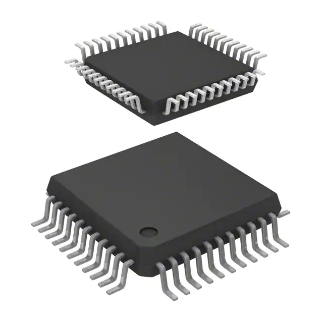
- Part No.:
- TSH512CYFT
- Manufacturer:
- STMicroelectronics
- Category:
- RF Transmitters
- Package:
- 44-LQFP
- Datasheet:
-
 TSH512CYFT.pdf
- Description:
- RF TX IC FM 400KHZ-11MHZ 44LQFP
- Quantity:
- Payment:

- Shipping:

Inventory:3,846
Please send an inquiry. Send us your inquiry, and we will respond immediately.
Product details
Overview
TSH512CYFT from STMicroelectronics is a dual FM infrared transmitter IC integrating two independent stereo audio transmission paths, each with low-noise LNA, ALC, pre-emphasis amplifier, voltage-controlled oscillator (0.4–11 MHz), and linear output buffer. It supports hi-fi stereo IR headphones, voice-activated wireless webcams, and video sub-carrier generation with VOX-driven power saving and mono standby mode.
For engineers reviewing the TSH512CYFT datasheet, TSH512CYFT pinout, TSH512CYFT application, or TSH512CYFT equivalent, key selection criteria include carrier frequency programmability (0.4–11 MHz), dual-channel ALC-regulated audio path (600–800 mVpp output), VOX-MUTE control logic, SBY pin for mono TX2 disable, and TQFP44 package compatibility with IR LED driver interface design.
Technical Context
The TSH512CYFT implements two fully independent FM transmitter channels (TX1/TX2), each with electret microphone bias (2.15–2.35 V), 7 MHz LNA gain-bandwidth product, and 20 dB ALC voltage gain. Its VCOs generate sinusoidal carriers (0.4–11 MHz) with 580–660 mVpp output into 1 kΩ load, enabling high-spectral-purity modulation for IR LED drive.
VOX circuitry uses three dedicated pins (VOX-INTS, VOX-SENS, VOX-TIMER) to configure audio-integrated activation timing and noise rejection, while the SBY pin forces TX2 into standby-reducing total supply current from 16 mA to 10 mA-enabling battery-efficient mono operation in headsets and webcams.
Key Specifications
| Parameter | Value and Actual Design Meaning |
|---|---|
| Supply voltage | 2.3–5.5 V - Enables direct Li-ion or dual-AA battery operation without external regulator |
| Carrier frequency range | 0.4–11 MHz - Covers standard IR audio bands (2.3/2.8 MHz stereo), video sub-carriers, and custom FM IF systems |
| Audio input support | Microphone- or line-level - Dual LNA inputs (LNA-INP1/INN1 & LNA-INP2/INN2) with 30 kΩ input resistance |
| ALC regulated output | 600–800 mVpp at PEA input - Ensures consistent FM deviation across supply and temperature variations |
| VOX-MUTE output | CMOS-compatible active-low signal - Directly gates LED driver enable or MCU wake-up interrupt |
| Standby current (TX2 off) | 10–11.5 mA - Reduces system power by ~40% in mono headset or voice-triggered camera mode |
| VCO output level | 580–660 mVpp into ≥1 kΩ - Matches typical LC tank impedance for clean carrier synthesis before buffer stage |
Pinout & Package
TQFP44 (10 × 10 mm, 0.8 mm pitch) - thermally enhanced quad flat pack with exposed thermal pad for sustained 18.6 mA operation at +85°C ambient.
| Pin | Circuit Role | Design Meaning |
|---|---|---|
| 5 (SBY) | Standby control input | Active-high logic disables TX2 oscillator and buffer - enables mono operation with reduced ICC_SBY |
| 27 (VOX-MUTE) | VOX mute output | Open-drain CMOS output; pulls low when audio detected - directly controls LED driver enable or MCU GPIO |
| 12/44 (LNA-INP1/LNA-INP2) | LNA positive input | Differential input for electret mic or line signal - 30 kΩ input resistance matches standard mic bias networks |
| 22/34 (VCO-OUT1/VCO-OUT2) | VCO sinusoidal output | High-impedance AC-coupled carrier source - requires external LC tank (e.g., 120 µH + 6–60 pF) for resonance tuning |
| 24/32 (BUF-IN1/BUF-IN2) | Output buffer input | 400 kΩ high-Z node - accepts VCO-OUT signal and drives external transistor (e.g., STZT2222A) for IR LED current |
| 25/31 (BUF-OUT1/BUF-OUT2) | Buffered RF output | 1.3–1.7 Vpp into 2 kΩ - sufficient to drive series-connected IR LEDs (e.g., HSDL4230) via current-limiting resistor |
Key Features
| Feature | Design Value |
|---|---|
| Dual independent FM transmitters | Separate LNA, ALC, PEA, VCO, and buffer per channel - enables true stereo IR headphone or left/right sub-carrier generation |
| Sinusoidal carrier generation | VCO outputs pure sine waves (not square) - simplifies bandpass filtering and improves adjacent-channel rejection in IR link |
| Integrated microphone bias | 2.25 V ±100 mV at 2.5 mA - eliminates external bias resistor; stable over -40°C to +85°C (260 ppm/°C drift) |
| VOX with adjustable sensitivity | VOX-SENS and VOX-INTS pins set detection threshold and integration time - avoids false triggers from ambient noise |
| Pre-emphasis amplifier (PEA) | 9 MHz GBW, 550 mVpp output into 22 kΩ - applies standard 50/15 µs audio pre-emphasis to counter IR channel high-frequency loss |
Applications
| IR Stereo Headphones | Voice-Activated Wireless Webcam |
|---|---|
|
Use Scenario: Consumer-grade wireless stereo headphones transmitting left/right audio over IR to paired receiver (e.g., TSH511). IC Role / Device Role / Timing Role: Dual-channel FM transmitter generating 2.3 MHz (right) and 2.8 MHz (left) carriers with ALC-regulated deviation and VOX-gated transmission. Use Value: 40% lower current draw during silence (VOX-MUTE = low), extended battery life, and <0.05% THD at 700 mVpp ensures hi-fi audio fidelity. |
Use Scenario: USB webcam with built-in microphone that activates IR audio streaming only when speech is detected. IC Role / Device Role / Timing Role: Mono FM sub-carrier generator using TX1 path; VOX-MUTE output wakes host MCU and enables IR LED driver. Use Value: Eliminates continuous IR transmission - reduces EMI, heat, and power consumption; SBY pin allows single-transmitter optimization. |
| Stereo Sub-Carrier Generator | FM IF Transmit System |
|
Use Scenario: Video transmitter embedding stereo audio as 5.5/6.0 MHz sub-carriers onto composite video signal. IC Role / Device Role / Timing Role: Dual VCO configured for precise sub-carrier frequencies; PEA applies pre-emphasis before FM modulation. Use Value: Carrier frequency tunable from 0.4–11 MHz with <±50 kHz stability - meets NTSC/PAL sub-carrier spec without external PLL. |
Use Scenario: Industrial short-range telemetry system using FM-modulated IR for analog sensor data transmission. IC Role / Device Role / Timing Role: Single-channel FM transmitter (TX1) with line-level input, ALC compression, and buffered RF output driving photodiode array. Use Value: 10 dB linear buffer gain and 1.3 Vpp output swing ensure robust signal-to-noise ratio over 5–10 m IR path with ambient light immunity. |
Equivalent & Alternatives
The following parts are listed as comparable options for similar dual FM transmitter applications.
| Alternative Part | Technical Difference | Application Difference | Selection Advice |
|---|---|---|---|
| MAX4410ETJ+ | Single-channel FM transmitter; no integrated VOX or SBY; requires external ALC loop and bias circuit | Limited to mono audio or requires dual ICs for stereo - increases BOM count and PCB area | Choose when cost-per-channel is critical and VOX/standby features are implemented externally |
| Si2151-A10-GM | RF tuner IC with integrated IF demodulator - not a transmitter; lacks LNA, ALC, PEA, and VCO sections | Designed for broadcast reception, not IR audio transmission - incompatible functional scope | Not suitable as functional replacement; only relevant for receiver-side companion designs |
Compared with MAX4410ETJ+, the TSH512CYFT integrates full stereo signal chain and power management in one TQFP44 package, reducing design effort and component count; Si2151-A10-GM serves a fundamentally different receive-oriented function and cannot substitute for FM IR transmission.
Availability
TSH512CYFT is available at Aetrix Electronics and suitable for infrared stereo transmitters, voice-activated wireless webcams, and stereo sub-carrier generators requiring stable component supply across industrial temperature ranges (-40°C to +85°C).
Supply support for TSH512CYFT includes scheduled delivery planning, volume procurement assistance, BOM continuity management, traceable sourcing, and lifecycle availability coordination for OEM customers, industrial embedded developers, connected-device designers, and electronics production programs.
Manufacturer
STMicroelectronics is a global semiconductor leader headquartered in Geneva, Switzerland, designing and manufacturing analog, mixed-signal, and power ICs for automotive, industrial, and consumer markets.
The TSH512CYFT belongs to ST's infrared audio transmission product line, engineered specifically for low-power, high-fidelity wireless audio links using infrared carriers - emphasizing spectral purity, battery efficiency, and system-level integration.
FAQ
What is the maximum recommended carrier frequency for reliable operation?
The TSH512CYFT is characterized up to 11 MHz, with guaranteed performance at 2.8 MHz (stereo headphones) and 5.5 MHz (video sub-carrier). At 11 MHz, VCO output drops to 569 mVpp minimum and phase noise degrades to –75 dBc at 1 kHz offset; use ≤8 MHz for robust SNR in production designs.
Can the TSH512CYFT drive IR LEDs directly without an external transistor?
No. The BUF-OUT pins deliver 1.3–1.7 Vpp AC into 2 kΩ but lack current drive capability for typical IR LEDs (requiring 20–100 mA). External NPN transistor (e.g., STZT2222A) or MOSFET is mandatory - BUF-OUT connects to base/gate, while collector/drain supplies LED current from VCC via current-limiting resistor.
How does the ALC section interact with the PEA amplifier?
The ALC regulates the signal level at its output node (VALC_OUT = 600–800 mVpp), which feeds directly into the PEA-INN pin. This ensures pre-emphasis is applied to a stabilized amplitude signal, preventing distortion from overdriving the PEA stage and maintaining consistent FM deviation regardless of input level variation.
Is the TQFP44 package RoHS-compliant and lead-free?
Yes. TSH512CYFT is manufactured in a RoHS-compliant, lead-free TQFP44 package per STMicroelectronics' ECOPACK2 specifications (document AN2604). The "YFT" suffix confirms lead-free finish, halogen-free molding compound, and JEDEC-standard reflow profile compatibility (peak 260°C).
TSH512CYFT Specifications
- Product attributes
- Attribute value
- Manufacturer:
- STMicroelectronics
- Series:
- Q
- Package/Case:
- 44-LQFP
- Packaging:
- Tape & Reel (TR)
- Product Status:
- Obsolete
- Programmable:
- Not Verified
- Frequency:
- 400kHz ~ 11MHz
- Applications:
- General Purpose
- Modulation or Protocol:
- FM
- Data Rate (Max):
- -
- Power - Output:
- -
- Current - Transmitting:
- 19.6mA
- Data Interface:
- PCB, Surface Mount
- Antenna Connector:
- PCB, Surface Mount
- Memory Size:
- -
- Features:
- -
- Voltage - Supply:
- 2.3V ~ 5.5V
- Operating Temperature:
- -40°C ~ 85°C
- Grade:
- Automotive
- Qualification:
- -
- Mounting Type:
- Surface Mount
- Supplier Device Package:
- 44-TQFP (10x10)
TSH512CYFT FAQ
1.How can I place an order for TSH512CYFT through Aetrix?
Please submit a Request for Quotation (RFQ) for TSH512CYFT on Aetrix. Our sales agent will provide a competitive quotation and guide you through the order confirmation once you accept the terms.
2.Are the price and stock information for TSH512CYFT reliable?
The price and inventory of TSH512CYFT are updated periodically and may fluctuate due to market conditions. Stock and pricing data are typically refreshed every 24 hours. Quotation validity for TSH512CYFT is usually 5 days.
3.What payment methods are accepted for TSH512CYFT?
We accept Wire Transfer, PayPal, Credit Card, Western Union, MoneyGram, and Escrow for TSH512CYFT transactions.
Note: Certain payment methods may incur a processing fee.
4.How is shipping managed for TSH512CYFT?
TSH512CYFT orders can be shipped via leading logistics carriers, including DHL, UPS, FedEx, TNT, or Registered Mail.
Once your TSH512CYFT order is processed, you will receive an email with the shipment details and tracking number.
Note: Tracking information may take up to 24 hours to appear. Express delivery typically takes 3–5 business days.
5.How can I obtain technical support or documentation for TSH512CYFT?
For technical support, including TSH512CYFT datasheets, pinout diagrams, or application guidance, please contact our engineering support team. They can provide detailed documentation and assistance for your TSH512CYFT requirements.
6.How does Aetrix verify that TSH512CYFT is sourced from the original manufacturer or authorized distributors?
All TSH512CYFT products on Aetrix are procured from qualified distributors and authorized channels. Our dedicated quality assurance team conducts strict verification, including traceability checks and, if necessary, third-party testing. This ensures that TSH512CYFT meets industry standards.
7.What is the process for return or replacement of TSH512CYFT?
All TSH512CYFT units undergo pre-shipment inspection (PSI). If there is an issue with TSH512CYFT, returns or replacements are accepted under the following conditions:
1.Quantity discrepancies, incorrect items, or visible external defects (such as breakage or corrosion), acknowledged by Aetrix.
2.The issue is reported within 90 days of delivery.
3.The TSH512CYFT part is unused and in its original packaging.
Return procedure for TSH512CYFT:
1.Submit a request within 90 days.
2.Obtain a Return Material Authorization (RMA) from Aetrix.
TSH512CYFT Tags

-
MICRF113YM6-TR
Microchip Technology
-
PIC12LF1840T39AT-I/ST
Microchip Technology

-
MAX41460GUB+T
Analog Devices Inc./Maxim Integrated
-
SX1230I066TRT
Semtech Corporation
-
SI4010-C2-GS
Silicon Labs
-
CC1070RSQR
Texas Instruments
-
TXM-418-LR
TE Connectivity Linx
-
TXM-433-LR
TE Connectivity Linx
-
TXM-418-KH3
TE Connectivity Linx

-
TX7332ZBX
Texas Instruments
-
MICRF114T-I/OT
Microchip Technology
-
MICRF112YMM-TR
Microchip Technology
Tech Hub

A practical engineering and sourcing framework covering lifecycle verification, lifetime-buy calculations, replacement qualification, supplier checks and counterfeit-risk controls.

TTL and CMOS logic families differ in thresholds, loading, output drive, power and timing. This engineering guide compares 74HC and 74HCT, calculates noise margins and checks 3.3 V/5 V compatibility.

A practical engineering guide to 3.3V and 5V logic compatibility, input thresholds, resistor dividers, translator ICs, MOSFET level shifting, I2C pull-ups, timing limits and power-sequencing risks.

The 74HC595 uses push-pull logic outputs, while the TPIC6B595 uses 50 V open-drain DMOS sinks for higher-power loads. This guide compares timing, current limits, 3.3 V interfacing, load wiring, thermal…

The 74HC595 converts serial data into eight stable parallel outputs. This guide covers pin functions, shift and storage timing, OE and MR behavior, drive-current limits, cascading, voltage compatibilit…

A technical comparison of level-sensitive latches and edge-triggered flip-flops, covering timing windows, setup and hold limits, master–slave operation, time borrowing, race-through, HDL inference and…

A D latch stores one bit while Enable controls when data can pass. This reference covers gate-level operation, truth tables, transparency, setup and hold timing, LE versus OE, common ICs and practical …

An SR latch stores one bit through cross-coupled feedback. This engineering reference covers NOR and NAND implementations, truth tables, forbidden-state recovery, gated operation, switch debouncing, fa…

Latch circuits retain one bit through feedback. This technical reference covers SR and D latches, truth tables, transparency, timing limits, latch-versus-flip-flop behavior, applications and common log…

An engineering guide to LED driver operation, constant-current and constant-voltage outputs, linear and switching topologies, dimming, IC selection, calculations, replacement compatibility, and fault c…


