
 My Inquiry
 My Account


Texas Instruments TUSB7320RKMR
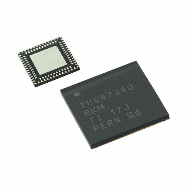
- Part No.:
- TUSB7320RKMR
- Manufacturer:
- Texas Instruments
- Category:
- Controllers
- Package:
- 100-WQFN Dual Rows, Exposed Pad
- Datasheet:
-
 TUSB7320RKMR.pdf
- Description:
- IC HUB CONTROLLER USB 100WQFN
- Quantity:
- Payment:

- Shipping:

Inventory:2,647
Please send an inquiry. Send us your inquiry, and we will respond immediately.
Product details
Overview
TUSB7320RKMR from Texas Instruments is a USB 3.0-compliant xHCI host controller IC implementing PCIe x1 Gen 2 upstream interface and supporting exactly two SuperSpeed USB downstream ports with independent power control, overcurrent detection, and per-port PHY tuning (swing/de-emphasis/equalization). It operates across 0–70°C industrial temperature range with 1.1V core and 3.3V I/O supplies, and targets embedded server and storage host bus adapter applications requiring compact, low-power USB host connectivity.
For engineers reviewing the TUSB7320RKMR datasheet, TUSB7320RKMR pinout, TUSB7320RKMR application, or TUSB7320RKMR equivalent, this page delivers verified technical context, validated pin functions, real-world use cases, and actionable alternative part guidance - all grounded in TI's official SLLSE76R production datasheet (Rev. AUGUST 2026).
Technical Context
The TUSB7320RKMR implements a full xHCI 1.0-compliant host controller with integrated USB 3.0 PHYs for two downstream ports, interfacing to the system via PCIe x1 Gen 2 (5 GT/s) with MSI-X support. Its architecture includes dedicated per-port power management (PWRON#/OVERCUR#), adaptive receiver equalization with FTC-reversed mode default, and programmable transmitter swing (16 levels, 2.7–1253 mVpp AC-coupled) and de-emphasis (16 levels, 0–69.3% amplitude reduction).
It requires no external flash for boot configuration, supports optional serial EEPROM for custom settings, and integrates internal spread-spectrum clock generation. The device uses a 48 MHz crystal or oscillator input (XI/XO), with FREQSEL strapped low, and features JTAG debug, I²C configuration interface (SCL/SDA), and four GPIOs for system integration.
Key Specifications
| Parameter | Value and Actual Design Meaning |
|---|---|
| USB Ports | 2 downstream SuperSpeed (5 Gbps) + HS/FS/LS backward compatibility per port |
| PCIe Interface | x1 Gen 2 (5 GT/s); compliant with PCIe Base Spec 2.1; supports MSI-X interrupts |
| Power Supplies | VDD11 = 1.045–1.21 V (core); VDD33/VDDA_3P3 = 3.0–3.6 V (I/O/analog) |
| Operating Temp | 0°C to 70°C ambient; junction max 105°C; RθJA = 25.6°C/W (WQFN-MR package) |
| Power (Active) | 1003 mW typical with 2 active SuperSpeed devices (1.05 V core / 3.3 V I/O) |
| Crystal Input | 48 MHz ±50 ppm; 12–24 pF load capacitance; ESR ≤ 50 Ω; XI/XO pins with 2 MΩ feedback resistor |
| ESD Rating | HBM ±1500 V, CDM ±500 V per JEDEC JS-001/JESD22-C101 |
Pinout & Package
Package: 100-pin WQFN-MR (RKM) with exposed thermal pad; 7 mm × 7 mm footprint; 0.5 mm pitch; RoHS-compliant.
| Pin/Terminal | Circuit Role | Design Meaning |
|---|---|---|
| PCIE_TXP / PCIE_TXN | PCIe Gen2 differential transmitter output | Drives PCIe link to host CPU/chipset; requires controlled 100 Ω differential impedance routing |
| PCIE_RXP / PCIE_RXN | PCIe Gen2 differential receiver input | Accepts PCIe reference clock and data; internal termination enabled; sensitive to noise coupling |
| USB_SSTXP_DN1 / USB_SSTXN_DN1 USB_SSTXP_DN2 / USB_SSTXN_DN2 |
SuperSpeed USB differential transmitter outputs (Port 1 & 2) | Drive 5 Gbps USB 3.0 signals; polarity swap permitted per port for layout flexibility |
| USB_SSRXP_DN1 / USB_SSRXN_DN1 USB_SSRXP_DN2 / USB_SSRXN_DN2 |
SuperSpeed USB differential receiver inputs (Port 1 & 2) | Adaptively equalized inputs; support channel loss compensation up to ~15 dB at 2.5 GHz |
| PWRON1# / PWRON2# | Active-low downstream port power enable | Controls external USB power switches; open-drain with internal pull-down; logic level matches VDD33 |
| OVERCUR1# / OVERCUR2# | Active-low downstream port overcurrent sense | Input detects external current-limit fault; asserted low during overcurrent; internal pull-up enabled |
| GRST# | Global reset input | Must be held low until all supplies and 48 MHz clock are stable; resets all internal registers to defaults |
| XI / XO | Crystal oscillator input/output | Supports 48 MHz fundamental-mode crystal; 2 MΩ feedback resistor required between XI and XO |
| FREQSEL | Frequency select strap | Must be tied low for 48 MHz operation; determines PLL multiplier setting for USB/PCIe clock domains |
| SCL / SDA | I²C configuration interface | Used to load EEPROM-based configuration or update runtime settings; pulled down if unused |
Key Features
| Feature | Design Value |
|---|---|
| PCIe x1 Gen2 host interface | Enables direct attachment to modern CPUs/chipsets without bridge logic; supports hot-plug and ASPM power states |
| Per-port independent power & overcurrent control | Allows selective port disablement and safe hot-swap implementation without affecting other ports or system stability |
| Programmable transmitter swing and de-emphasis | 16-level swing (2.7–1253 mVpp) and 16-level de-emphasis (0–69.3%) per port optimize signal integrity across varied PCB trace lengths |
| Adaptive receiver equalizer with FTC-reversed mode | Automatically compensates for frequency-dependent channel loss; FTC-reversed mode ensures robust lock under high jitter conditions |
| No external flash required | Reduces BOM cost and board space; default xHCI configuration stored in on-die ROM; optional EEPROM for customization |
| Integrated spread-spectrum clocking | Lowers EMI emissions without external components; supports low-cost crystal or oscillator sources |
Applications
| Rack Server USB Expansion | Embedded Storage HBA |
|---|---|
|
Use Scenario: Adding dual SuperSpeed USB ports to a 1U rack server motherboard for front-panel or rear I/O expansion. IC Role / Device Role / Timing Role: xHCI host controller managing USB enumeration, bandwidth allocation, and link power management for attached peripherals. Use Value: Enables native OS support (Windows/Linux) without driver customization; reduces latency vs. USB 2.0 hubs; supports simultaneous 5 Gbps transfers per port. |
Use Scenario: Integrating USB 3.0 host capability into a compact SAS/SATA host bus adapter for mixed-media storage enclosures. IC Role / Device Role / Timing Role: USB host controller providing high-bandwidth connectivity to USB-attached NVMe enclosures or RAID JBODs. Use Value: Delivers >400 MB/s sustained throughput per port; leverages PCIe Gen2 x1 bandwidth efficiently; supports UASP protocol for reduced command overhead. |
| Industrial PC Motherboard | High-Density Workstation Add-in Card |
|
Use Scenario: Embedding dual USB 3.0 ports on an extended-temperature industrial PC motherboard for machine vision camera interfaces. IC Role / Device Role / Timing Role: xHCI-compliant host controller handling isochronous video streaming with guaranteed bandwidth and low-latency scheduling. Use Value: Supports UVC/UAC class drivers out-of-box; maintains timing accuracy under thermal stress (0–70°C); enables plug-and-play camera deployment. |
Use Scenario: Implementing a low-profile PCIe x1 add-in card with two isolated USB 3.0 ports for workstation docking stations. IC Role / Device Role / Timing Role: Host controller with independent port power control enabling per-port hot-swap and individual overcurrent protection. Use Value: Eliminates need for discrete power switches and current sensors; reduces component count by 7+ parts per port; simplifies compliance testing. |
Equivalent & Alternatives
The following parts are listed as comparable options for similar USB 3.0 host controller applications.
| Alternative Part | Technical Difference | Application Difference | Selection Advice |
|---|---|---|---|
| VIA Labs VL805-Q4 | PCIe x1 Gen2, 4-port USB 3.0 host controller; requires external EEPROM; higher active power (1.5 W typical) | Designed for consumer desktop/motherboard use; lacks industrial temp rating and adaptive equalizer tuning granularity | Select when 4-port density is required and industrial temp operation is not mandatory |
| ASMedia ASM1083 | PCIe x1 Gen1 (2.5 GT/s) bridge + USB 3.0 controller; 2-port; no integrated PHY; requires external USB 3.0 transceivers | Legacy platform support only; lower bandwidth ceiling; higher BOM complexity and layout sensitivity | Select only for Gen1-limited systems where PHY separation is acceptable and cost is primary constraint |
Compared with VL805-Q4 and ASM1083, the TUSB7320RKMR offers superior signal integrity tuning (adaptive equalizer + 16-level swing/de-emphasis), industrial temperature support, lower power consumption in active states, and integrated PHY - making it optimal for space-constrained, thermally demanding embedded host applications.
Availability
TUSB7320RKMR is available at Aetrix Electronics and suitable for rack server expansion, embedded storage HBA, and industrial PC motherboard designs requiring stable component supply, long-term lifecycle assurance, and traceable sourcing.
Supply support for TUSB7320RKMR includes scheduled delivery planning, volume procurement assistance, BOM continuity management, traceable sourcing, and lifecycle availability coordination for OEM customers, industrial embedded developers, connected-device designers, and electronics production programs.
Manufacturer
Texas Instruments is a global semiconductor leader specializing in analog, embedded processing, and connectivity solutions, with decades of expertise in high-speed interface ICs and industrial-grade reliability.
The TUSB73x0 product line was designed specifically for embedded USB host applications in servers, storage, and industrial computing - delivering xHCI compliance, PCIe Gen2 integration, and robust PHY tuning in compact WQFN packages.
FAQ
What is the maximum number of USB devices supported by the TUSB7320RKMR?
The TUSB7320RKMR supports up to two downstream USB ports, each capable of connecting one SuperSpeed device or multiple lower-speed devices via a USB hub. As an xHCI-compliant host controller, it handles up to 255 total devices in a tree topology, but physical port count remains fixed at two. The TUSB7320RKMR does not support more than two concurrent SuperSpeed links.
Does the TUSB7320RKMR require an external EEPROM to function?
No, the TUSB7320RKMR operates with default xHCI configuration loaded from on-die ROM and requires no external EEPROM. An optional serial EEPROM may be used for custom vendor ID, product ID, or PHY tuning parameters, but it is not mandatory for basic USB host functionality. The TUSB7320RKMR boots and enumerates correctly without any external non-volatile memory.
What is the purpose of the R1EXT and R1EXTRTN pins on the TUSB7320RKMR?
R1EXT and R1EXTRTN form a precision calibration path for the internal USB PHY reference current. A 9.09 kΩ ±1% resistor must be connected between these pins to ensure accurate USB 3.0 transmitter amplitude and receiver threshold levels. Omitting or misrouting this resistor causes USB link training failures or unstable SuperSpeed connections. This calibration is mandatory for TUSB7320RKMR operation.
Can the TUSB7320RKMR support USB 2.0 and USB 1.1 devices on its downstream ports?
Yes, the TUSB7320RKMR provides full backward compatibility: each downstream port supports SuperSpeed (5 Gbps), High-Speed (480 Mbps), Full-Speed (12 Mbps), and Low-Speed (1.5 Mbps) USB devices via automatic speed negotiation. The integrated dual-mode PHY handles all signaling layers without external components, and the xHCI controller manages scheduling and bandwidth allocation across mixed-speed topologies.
Is the TUSB7320RKMR pin-compatible with the TUSB7340RKMR?
Yes, the TUSB7320RKMR and TUSB7340RKMR share identical 100-pin RKM (WQFN-MR) packaging and pinout, enabling dual-layout motherboard designs. However, TUSB7340RKMR exposes additional USB port signals (DN3/DN4) as no-connects on TUSB7320RKMR; unused pins must remain unconnected or tied per TI's layout guidelines. Functionality remains strictly limited to two ports on TUSB7320RKMR.
TUSB7320RKMR Specifications
- Product attributes
- Attribute value
- Manufacturer:
- Texas Instruments
- Package/Case:
- 100-WQFN Dual Rows, Exposed Pad
- Programmable:
- Not Verified
- Protocol:
- USB
- Function:
- Host Controller
- Interface:
- USB, PCIe
- Standards:
- USB 3.0
- Voltage - Supply:
- 1.1V, 3.3V
- Current - Supply:
- -
- Operating Temperature:
- 0°C ~ 70°C
- Supplier Device Package:
- 100-WQFN-MR (9x9)
- Grade:
- -
- Qualification:
- -
TUSB7320RKMR FAQ
1.How can I place an order for TUSB7320RKMR through Aetrix?
Please submit a Request for Quotation (RFQ) for TUSB7320RKMR on Aetrix. Our sales agent will provide a competitive quotation and guide you through the order confirmation once you accept the terms.
2.Are the price and stock information for TUSB7320RKMR reliable?
The price and inventory of TUSB7320RKMR are updated periodically and may fluctuate due to market conditions. Stock and pricing data are typically refreshed every 24 hours. Quotation validity for TUSB7320RKMR is usually 5 days.
3.What payment methods are accepted for TUSB7320RKMR?
We accept Wire Transfer, PayPal, Credit Card, Western Union, MoneyGram, and Escrow for TUSB7320RKMR transactions.
Note: Certain payment methods may incur a processing fee.
4.How is shipping managed for TUSB7320RKMR?
TUSB7320RKMR orders can be shipped via leading logistics carriers, including DHL, UPS, FedEx, TNT, or Registered Mail.
Once your TUSB7320RKMR order is processed, you will receive an email with the shipment details and tracking number.
Note: Tracking information may take up to 24 hours to appear. Express delivery typically takes 3–5 business days.
5.How can I obtain technical support or documentation for TUSB7320RKMR?
For technical support, including TUSB7320RKMR datasheets, pinout diagrams, or application guidance, please contact our engineering support team. They can provide detailed documentation and assistance for your TUSB7320RKMR requirements.
6.How does Aetrix verify that TUSB7320RKMR is sourced from the original manufacturer or authorized distributors?
All TUSB7320RKMR products on Aetrix are procured from qualified distributors and authorized channels. Our dedicated quality assurance team conducts strict verification, including traceability checks and, if necessary, third-party testing. This ensures that TUSB7320RKMR meets industry standards.
7.What is the process for return or replacement of TUSB7320RKMR?
All TUSB7320RKMR units undergo pre-shipment inspection (PSI). If there is an issue with TUSB7320RKMR, returns or replacements are accepted under the following conditions:
1.Quantity discrepancies, incorrect items, or visible external defects (such as breakage or corrosion), acknowledged by Aetrix.
2.The issue is reported within 90 days of delivery.
3.The TUSB7320RKMR part is unused and in its original packaging.
Return procedure for TUSB7320RKMR:
1.Submit a request within 90 days.
2.Obtain a Return Material Authorization (RMA) from Aetrix.
TUSB7320RKMR Tags

-
PTN5150AHXMP
NXP Semiconductors

-
USB3740B-AI9-TR
Microchip Technology

-
USB3740B-AI2-TR
Microchip Technology

-
USB3300-EZK-TR
Microchip Technology
-
USB3300-EZK
Microchip Technology

-
FUSB340TMX
onsemi

-
FUSB302BMPX
onsemi

-
DP83826IRHBR
Texas Instruments

-
MCP2518FDT-E/QBB
Microchip Technology
-
FUSB302MPX
onsemi

-
MCP2518FDT-E/SL
Microchip Technology

-
FT260Q-R
FTDI, Future Technology Devices International Ltd
Tech Hub

A practical engineering guide to 3.3V and 5V logic compatibility, input thresholds, resistor dividers, translator ICs, MOSFET level shifting, I2C pull-ups, timing limits and power-sequencing risks.

The 74HC595 uses push-pull logic outputs, while the TPIC6B595 uses 50 V open-drain DMOS sinks for higher-power loads. This guide compares timing, current limits, 3.3 V interfacing, load wiring, thermal…

The 74HC595 converts serial data into eight stable parallel outputs. This guide covers pin functions, shift and storage timing, OE and MR behavior, drive-current limits, cascading, voltage compatibilit…

A technical comparison of level-sensitive latches and edge-triggered flip-flops, covering timing windows, setup and hold limits, master–slave operation, time borrowing, race-through, HDL inference and…

A D latch stores one bit while Enable controls when data can pass. This reference covers gate-level operation, truth tables, transparency, setup and hold timing, LE versus OE, common ICs and practical …

An SR latch stores one bit through cross-coupled feedback. This engineering reference covers NOR and NAND implementations, truth tables, forbidden-state recovery, gated operation, switch debouncing, fa…

Latch circuits retain one bit through feedback. This technical reference covers SR and D latches, truth tables, transparency, timing limits, latch-versus-flip-flop behavior, applications and common log…

An engineering guide to LED driver operation, constant-current and constant-voltage outputs, linear and switching topologies, dimming, IC selection, calculations, replacement compatibility, and fault c…

Operational amplifier guide covering op amp basics, feedback, ideal vs real op amps, common configurations, buffer circuits, offset, bias current, gain-bandwidth, slew rate, rail-to-rail limits and sel…

Jumper cables guide covering safe connection order, red and black clamp placement, final ground connection, cable gauge, length, clamp quality, copper vs CCA cables, jump starter comparison and battery…


