
 My Inquiry
 My Account


Texas Instruments TXS4555RUTR
- Part No.:
- TXS4555RUTR
- Manufacturer:
- Texas Instruments
- Category:
- Translators, Level Shifters
- Package:
- Datasheet:
-
 TXS4555RUTR.pdf
- Description:
- IC TRANSLTR BIDIRECTIONAL 12UQFN
- Quantity:
- Payment:

- Shipping:

Inventory:14,773
Please send an inquiry. Send us your inquiry, and we will respond immediately.
Product details
Overview
TXS4555RUTR from Texas Instruments is a SIM card power supply and bidirectional level translator IC for mobile baseband-to-SIM interfacing. It integrates a 50mA LDO with selectable 1.8V/2.95V output, supports ISO/IEC 7816-3 shutdown sequencing, operates from 1.65–3.3V VCC and 2.3–5.5V VBATT, and delivers 8kV HBM ESD protection on SIM pins - deployed in GSM/3G handhelds requiring Class-B/C SIM compliance.
For engineers reviewing the TXS4555RUTR datasheet, TXS4555RUTR pinout, TXS4555RUTR application, or TXS4555RUTR equivalent, this page provides verified package mapping (12-pin UQFN), confirmed LDO dropout (≤100mV @50mA), validated SIM-side shutdown timing, real-world PSRR (50dB @1kHz), and alternative selection guidance aligned with TI's official RUT-package variants and functional equivalents.
Technical Context
The TXS4555RUTR implements a dual-domain architecture: an A-side level translator (VCC-referenced I/O, CLK, RST, EN, SEL) interfaces with low-voltage baseband processors, while a B-side (SIM_CLK, SIM_RST, SIM_I/O, VSIM) drives the SIM card at either 1.8V (Class-C) or 2.95V (Class-B) under ISO 7816-3-compliant power-down sequencing. The integrated PMOS LDO regulates VSIM from VBATT with ultra-low dropout and fast 400µs startup.
Its functional block includes independent pull-up/pull-down networks (16–24kΩ on I/O, 10–18kΩ on SIM_I/O, 3kΩ active pull-down during shutdown), bidirectional signal translation with 8pF I/O capacitance, and thermal protection that disables VSIM above ~160°C. All SIM-side pins feature 8kV HBM ESD rating; other pins meet 2kV HBM/500V CDM.
Key Specifications
| Parameter | Value and Actual Design Meaning |
|---|---|
| LDO Output Voltage | Selectable 1.8V (SEL = GND) or 2.95V (SEL = VCC); enables single design support for both SIM Class-C and Class-B cards. |
| Max Dropout Voltage | 100mV at 50mA load; allows stable VSIM regulation even when VBATT drops to 2.9V (for 2.95V mode) or 1.9V (for 1.8V mode). |
| ESD Protection (SIM pins) | 8kV HBM per JESD22-A114; eliminates need for external TVS diodes on SIM interface lines in portable designs. |
| Shutdown Current | 3.5µA at TJ = 85°C; ensures minimal battery drain during phone standby or power-off states. |
| VSIM Start-up Time | 400µs with 1µF output capacitor; meets GSM/3G timing requirements for SIM power-on initialization. |
| PSRR @ 1kHz | 50dB with 1µF COUT; suppresses VBATT ripple (e.g., from switching DC/DC converters) to maintain clean SIM supply. |
| Operating Temperature | –40°C to +85°C ambient; qualified for industrial-grade mobile handset operation across global climates. |
Pinout & Package
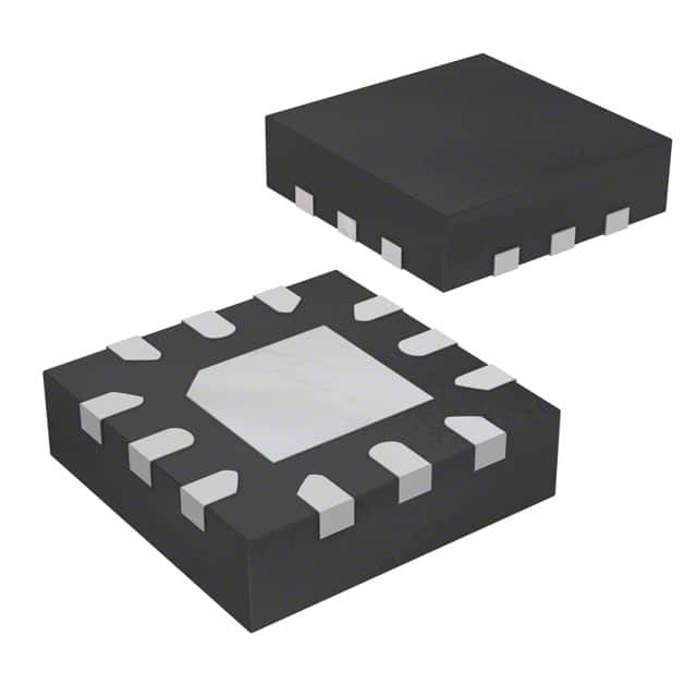
TXS4555RUTR uses a 12-pin UQFN (RUT) package measuring 2.00mm × 1.70mm with 0.4mm pitch and exposed thermal pad (connected to GND). Pin 1 is located in Quadrant Q1 per tape-and-reel orientation.
| Pin/Terminal | Circuit Role | Design Meaning |
|---|---|---|
| SEL | Voltage select input | Logic level determines VSIM output: low = 1.8V, high = 2.95V; referenced to VCC. |
| GND | Ground reference | Common return for all domains; thermal pad must be soldered to PCB ground plane for thermal performance. |
| EN | Enable control input | Pull low to disable LDO and place all SIM outputs (SIM_CLK, SIM_RST, SIM_I/O) in Hi-Z state with ISO 7816-3 shutdown sequence. |
| I/O | A-side bidirectional data | Connects to baseband processor I/O; translates logic levels between VCC domain and VSIM domain. |
| RST | A-side reset input | Active-high signal from baseband processor to initiate SIM reset via internal translator path. |
| CLK | A-side clock input | Drives SIM_CLK output through level-shifting circuitry; supports up to 25MHz clock frequency. |
| SIM_CLK | B-side clock output | Delivers translated clock to SIM card connector; features internal 10–18kΩ pull-up and 3kΩ active pull-down during shutdown. |
| VCC | A-port power supply | Supplies all control inputs and A-side I/Os; operates from 1.65V to 3.3V - compatible with 1.8V/2.8V/3.0V baseband cores. |
| VBATT | LDO input supply | Direct connection to battery rail (2.3V–5.5V); powers internal LDO and enables wide-input portable operation. |
| VSIM | SIM card power output | Regulated 1.8V or 2.95V output sourcing up to 50mA; supplies SIM card and drives SIM-side signals. |
| SIM_I/O | B-side bidirectional data | Connects to SIM card I/O pin; includes programmable pull-up (10–18kΩ) and active pull-down during EN=low. |
| SIM_RST | B-side reset output | Translates RST input to SIM-compatible reset pulse; first signal disabled in ISO 7816-3 shutdown sequence. |
Key Features
| Feature | Design Value |
|---|---|
| ISO 7816-3 compliant shutdown | Sequential deactivation of SIM_RST → SIM_CLK → SIM_I/O → VSIM upon EN assertion, preventing data corruption during hot removal or power loss. |
| Dual-class SIM voltage support | Single IC supports both 1.8V (Class-C) and 2.95V (Class-B) SIM cards via SEL pin - eliminates BOM variants and layout changes across product SKUs. |
| Ultra-low LDO dropout | 100mV max at full 50mA load ensures reliable VSIM regulation even as battery voltage declines below 3.0V in end-of-life conditions. |
| Integrated SIM-side ESD protection | 8kV HBM on SIM_CLK/SIM_RST/SIM_I/O pins removes need for discrete ESD components, reducing BOM count and board area in space-constrained handsets. |
| Thermal shutdown with hysteresis | Disables VSIM above ~160°C junction temperature and re-enables at ~140°C - protects against sustained overloads without permanent latch-off. |
Applications
| Mobile Handset SIM Interface | GSM/3G Baseband Integration |
|---|---|
|
Use Scenario: Integrating a 1.8V/2.95V SIM card into a smartphone using a 1.8V baseband processor with shared battery rail. IC Role / Device Role / Timing Role: TXS4555RUTR acts as the sole interface IC - translating baseband I/O/CLK/RST signals, regulating VSIM, and enforcing ISO 7816-3 shutdown timing. Use Value: Eliminates discrete LDO + level shifter + ESD solution; reduces component count by ≥4 parts and saves >1.5mm² PCB area in 2mm × 1.7mm footprint. |
Use Scenario: Enabling dual-SIM functionality in a compact LTE modem module where space and thermal budget are constrained. IC Role / Device Role / Timing Role: TXS4555RUTR provides independent VSIM regulation and signal translation for each SIM slot, with SEL pins configured for mixed Class-B/C operation. Use Value: Achieves 50mA per SIM channel with <100mV dropout, enabling simultaneous SIM operation from a single 3.6V Li-ion cell without voltage headroom compromise. |
| Industrial M2M SIM Module | Wearables with Hot-Swappable SIM |
|
Use Scenario: Deploying SIM-based cellular connectivity in ruggedized telematics units operating from –40°C to +85°C. IC Role / Device Role / Timing Role: TXS4555RUTR serves as the hardened SIM interface - delivering guaranteed 1.8V/2.95V output, 8kV ESD immunity, and thermal protection across full temp range. Use Value: Meets extended temperature qualification without derating; avoids field failures due to SIM interface instability during thermal cycling or voltage transients. |
Use Scenario: Supporting user-replaceable SIM in fitness trackers where accidental insertion/removal must not corrupt stored credentials. IC Role / Device Role / Timing Role: TXS4555RUTR executes precise ISO 7816-3 shutdown sequence upon EN deassertion, ensuring SIM_RST deactivates before SIM_CLK/SIM_I/O. Use Value: Prevents partial writes or bus contention during hot swap, maintaining SIM file system integrity and eliminating need for host-side recovery routines. |
Equivalent & Alternatives
The following parts are listed as comparable options for similar SIM card power supply and level translation applications.
| Alternative Part | Technical Difference | Application Difference | Selection Advice |
|---|---|---|---|
| TXS4555RGTR | Same die, 16-pin VQFN (3mm × 3mm) package; higher θJA (47°C/W vs 87.2°C/W); requires larger PCB footprint. | Preferred for designs with available board area and higher thermal margin; supports same electrical specs and pin functions as TXS4555RUTR. | Select TXS4555RGTR only if thermal design permits larger package or if existing layout uses RGT footprint. |
| MAX16070ETA+ | Dedicated 1.8V/3.0V SIM LDO (no integrated level translation); 6-pin TDFN; lacks ISO 7816-3 shutdown, SIM-side ESD, and bidirectional I/O capability. | Requires external level translators and ESD protection; suitable only when baseband and SIM operate at same voltage or translation is handled elsewhere. | Choose MAX16070ETA+ only when level translation is implemented separately and board space allows discrete solution with added complexity. |
Compared with TXS4555RGTR, the TXS4555RUTR offers 44% smaller footprint and better thermal resistance in thin-profile handhelds; compared with MAX16070ETA+, it integrates translation, shutdown, and ESD - reducing total solution size by ≥60% and eliminating four external components.
Availability
TXS4555RUTR is available at Aetrix Electronics and suitable for mobile handset design, GSM/3G baseband integration, and industrial M2M SIM modules requiring stable component supply, long-term lifecycle assurance, and RoHS-compliant packaging.
Supply support for TXS4555RUTR includes scheduled delivery planning, volume procurement assistance, BOM continuity management, traceable sourcing, and lifecycle availability coordination for OEM customers, industrial embedded developers, connected-device designers, and electronics production programs.
Manufacturer
Texas Instruments is a global semiconductor company specializing in analog, embedded processing, and connectivity technologies, with leadership in power management and interface solutions for portable electronics.
The TXS4555RUTR belongs to TI's SIM interface power and translation product line, engineered specifically to consolidate LDO regulation, bidirectional level shifting, ISO-compliant shutdown, and robust ESD protection into a single miniature package for space- and power-constrained mobile platforms.
FAQ
What is the maximum output current capability of the TXS4555RUTR LDO?
The TXS4555RUTR LDO delivers up to 50mA continuous output current at either 1.8V or 2.95V. Its short-circuit current is rated at 145mA, and it includes internal current limiting and thermal shutdown to protect against sustained overload. This 50mA rating fully supports standard SIM card operating current requirements across GSM, UMTS, and LTE categories, and is validated across the full –40°C to +85°C ambient temperature range specified for the TXS4555RUTR.
Does the TXS4555RUTR support hot-swap of SIM cards?
Yes, the TXS4555RUTR supports safe SIM hot-swap via its ISO/IEC 7816-3-compliant shutdown sequence. When EN is pulled low, TXS4555RUTR sequentially disables SIM_RST, then SIM_CLK, then SIM_I/O, and finally VSIM - ensuring no bus contention or partial writes occur. This behavior is confirmed in the device's functional description and Figure 4-1 of the TXS4555RUTR datasheet, making it suitable for wearables and modular devices with user-accessible SIM slots.
What is the recommended output capacitor for the TXS4555RUTR LDO?
The TXS4555RUTR LDO requires a minimum 1µF ceramic output capacitor (X5R or X7R dielectric) placed close to the VSIM and GND pins. TI specifies this value for stability, transient response, and PSRR optimization - and confirms compatibility with standard 1µF capacitors having ESR < 1Ω. Larger values improve load transient suppression but do not affect basic regulation; the 1µF value is sufficient for all nominal SIM card current profiles defined in the TXS4555RUTR datasheet.
How does the TXS4555RUTR handle ESD protection on SIM interface pins?
The TXS4555RUTR provides 8kV HBM ESD protection specifically on SIM_CLK, SIM_RST, and SIM_I/O pins - exceeding JEDEC JESD22-A114 requirements. This is achieved through integrated on-die protection structures, eliminating the need for external TVS diodes. All other pins (e.g., VCC, EN, SEL) are rated for standard 2kV HBM. This differential ESD hardening is explicitly documented in Section 4.2 of the TXS4555RUTR datasheet and validated in production testing.
Can the TXS4555RUTR operate with a 2.5V VCC supply?
Yes, the TXS4555RUTR supports VCC from 1.65V to 3.3V, making 2.5V fully within its recommended operating range. At 2.5V VCC, all level-translated signals (I/O, CLK, RST) maintain valid VIH/VIL thresholds per Section 4.4 of the datasheet, and the internal LDO continues to regulate VSIM independently from VBATT. This flexibility allows direct interfacing with common 2.5V or 2.8V baseband processor I/O domains without additional voltage translation.
TXS4555RUTR Specifications
- Product attributes
- Attribute value
- Manufacturer:
- Texas Instruments
- Series:
- -
- Package/Case:
- Packaging:
- Tape & Reel (TR)
- Product Status:
- Active
- Translator Type:
- Voltage Level
- Channel Type:
- Bidirectional
- Number of Circuits:
- 1
- Channels per Circuit:
- 1
- Voltage - VCCA:
- 1.65 V ~ 3.3 V
- Voltage - VCCB:
- 2.3 V ~ 5.5 V
- Input Signal:
- -
- Output Signal:
- -
- Output Type:
- Tri-State, Non-Inverted
- Data Rate:
- -
- Operating Temperature:
- -40°C ~ 85°C (TA)
- Grade:
- -
- Qualification:
- -
- Features:
- SIM Card Interface
- Mounting Type:
- Surface Mount
- Supplier Device Package:
- 12-UFQFN
TXS4555RUTR FAQ
1.How can I place an order for TXS4555RUTR through Aetrix?
Please submit a Request for Quotation (RFQ) for TXS4555RUTR on Aetrix. Our sales agent will provide a competitive quotation and guide you through the order confirmation once you accept the terms.
2.Are the price and stock information for TXS4555RUTR reliable?
The price and inventory of TXS4555RUTR are updated periodically and may fluctuate due to market conditions. Stock and pricing data are typically refreshed every 24 hours. Quotation validity for TXS4555RUTR is usually 5 days.
3.What payment methods are accepted for TXS4555RUTR?
We accept Wire Transfer, PayPal, Credit Card, Western Union, MoneyGram, and Escrow for TXS4555RUTR transactions.
Note: Certain payment methods may incur a processing fee.
4.How is shipping managed for TXS4555RUTR?
TXS4555RUTR orders can be shipped via leading logistics carriers, including DHL, UPS, FedEx, TNT, or Registered Mail.
Once your TXS4555RUTR order is processed, you will receive an email with the shipment details and tracking number.
Note: Tracking information may take up to 24 hours to appear. Express delivery typically takes 3–5 business days.
5.How can I obtain technical support or documentation for TXS4555RUTR?
For technical support, including TXS4555RUTR datasheets, pinout diagrams, or application guidance, please contact our engineering support team. They can provide detailed documentation and assistance for your TXS4555RUTR requirements.
6.How does Aetrix verify that TXS4555RUTR is sourced from the original manufacturer or authorized distributors?
All TXS4555RUTR products on Aetrix are procured from qualified distributors and authorized channels. Our dedicated quality assurance team conducts strict verification, including traceability checks and, if necessary, third-party testing. This ensures that TXS4555RUTR meets industry standards.
7.What is the process for return or replacement of TXS4555RUTR?
All TXS4555RUTR units undergo pre-shipment inspection (PSI). If there is an issue with TXS4555RUTR, returns or replacements are accepted under the following conditions:
1.Quantity discrepancies, incorrect items, or visible external defects (such as breakage or corrosion), acknowledged by Aetrix.
2.The issue is reported within 90 days of delivery.
3.The TXS4555RUTR part is unused and in its original packaging.
Return procedure for TXS4555RUTR:
1.Submit a request within 90 days.
2.Obtain a Return Material Authorization (RMA) from Aetrix.
TXS4555RUTR Tags
-
74LVC1T45GW,125
Nexperia USA Inc.
-
74LVCH2T45DC,125
Nexperia USA Inc.

-
SN74LVC1T45DBVR
Texas Instruments
-
SN74LVC1T45DRLR
Texas Instruments
-
SN74LVC1T45DPKR
Texas Instruments
-
SN74LVC2T45DCTR
Texas Instruments
-
74LVC2T45GT,115
Nexperia USA Inc.
-
SN74LVC1T45YZPR
Texas Instruments

-
LSF0102DCUR
Texas Instruments

-
SN74LVC1T45DCKR
Texas Instruments
-
TXS0102DCTR
Texas Instruments
-
FXLP34P5X
onsemi
Tech Hub

A practical engineering guide to 3.3V and 5V logic compatibility, input thresholds, resistor dividers, translator ICs, MOSFET level shifting, I2C pull-ups, timing limits and power-sequencing risks.

The 74HC595 uses push-pull logic outputs, while the TPIC6B595 uses 50 V open-drain DMOS sinks for higher-power loads. This guide compares timing, current limits, 3.3 V interfacing, load wiring, thermal…

The 74HC595 converts serial data into eight stable parallel outputs. This guide covers pin functions, shift and storage timing, OE and MR behavior, drive-current limits, cascading, voltage compatibilit…

A technical comparison of level-sensitive latches and edge-triggered flip-flops, covering timing windows, setup and hold limits, master–slave operation, time borrowing, race-through, HDL inference and…

A D latch stores one bit while Enable controls when data can pass. This reference covers gate-level operation, truth tables, transparency, setup and hold timing, LE versus OE, common ICs and practical …

An SR latch stores one bit through cross-coupled feedback. This engineering reference covers NOR and NAND implementations, truth tables, forbidden-state recovery, gated operation, switch debouncing, fa…

Latch circuits retain one bit through feedback. This technical reference covers SR and D latches, truth tables, transparency, timing limits, latch-versus-flip-flop behavior, applications and common log…

An engineering guide to LED driver operation, constant-current and constant-voltage outputs, linear and switching topologies, dimming, IC selection, calculations, replacement compatibility, and fault c…

Operational amplifier guide covering op amp basics, feedback, ideal vs real op amps, common configurations, buffer circuits, offset, bias current, gain-bandwidth, slew rate, rail-to-rail limits and sel…

Jumper cables guide covering safe connection order, red and black clamp placement, final ground connection, cable gauge, length, clamp quality, copper vs CCA cables, jump starter comparison and battery…


