
 My Inquiry
 My Account


Microchip Technology U2793B-NFSG3H 19
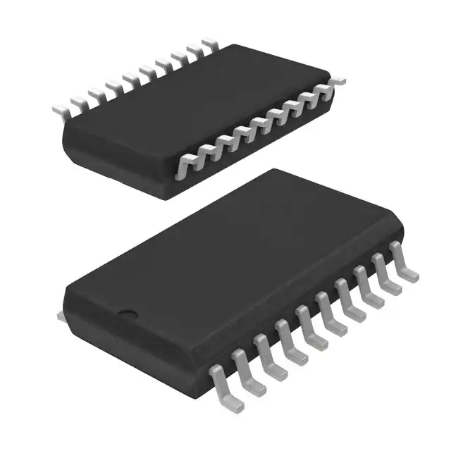
- Part No.:
- U2793B-NFSG3H 19
- Manufacturer:
- Microchip Technology
- Category:
- RF Modulators
- Package:
- 20-LSSOP (0.173", 4.40mm Width)
- Datasheet:
-
 U2793B-NFSG3H 19.pdf
- Description:
- RF MODULATOR 20LSSOP
- Quantity:
- Payment:

- Shipping:

Inventory:4,957
Please send an inquiry. Send us your inquiry, and we will respond immediately.
Product details
Overview
U2793B-NFSG3H from Atmel is a 300-MHz quadrature modulator IC designed for digital radio up-conversion, featuring single-ended 50-Ω RF/LO ports, 90° phase-control loop, duty-cycle regeneration, and low-power 15 mA operation at 5 V. It supports LO frequencies from 30 MHz to 300 MHz and delivers ≥45 dB LO suppression and ≥45 dB sideband suppression in GSM, PCN, JDC, and WLAN systems.
For engineers reviewing the U2793B-NFSG3H datasheet, U2793B-NFSG3H pinout, U2793B-NFSG3H application, or U2793B-NFSG3H equivalent, key selection criteria include its adjustment-free I/Q modulation architecture, spurious performance tunability via pins 19/20, power-down mode, and SSO20 package compatibility with high-density RF layouts.
Technical Context
The U2793B-NFSG3H integrates a frequency doubler, duty-cycle regenerator, and precision 90° control loop to enable accurate quadrature modulation without external calibration. Its baseband inputs accept differential signals up to 1.5 Vpp across 0–50 MHz, while the LO path accepts -15 dBm single-ended input with 50 Ω impedance (50 Ω + 15 pF).
It operates from 4.5 V to 5.5 V over -40°C to +85°C ambient, with reference voltage (2.5 V ±125 mV) on pin 13 and dual low-pass/power-control terminals (pins 19/20) enabling output level and spurious optimization-especially critical for low-frequency LO operation below 100 MHz.
Key Specifications
| Parameter | Value and Actual Design Meaning |
|---|---|
| LO Frequency Range | 30 MHz to 300 MHz - enables direct synthesis for GSM/PCN/JDC bands without IF staging |
| Supply Current | 15 mA at 5 V - reduces thermal load and simplifies power rail design in portable radios |
| LO Suppression | ≥45 dB typical - minimizes carrier feedthrough in zero-IF transmitters |
| Sideband Suppression | ≥45 dB typical - ensures clean spectral mask compliance in narrowband digital standards |
| Phase Error | <1° - maintains EVM integrity in QPSK/16-QAM modulation schemes |
| Amplitude Error | <±0.25 dB - preserves constellation symmetry and adjacent channel power ratio (ACPR) |
| Output Power | -3 to +2 dBm - drives next-stage mixer (e.g., U2795B) without external amplification |
Pinout & Package
U2793B-NFSG3H uses a 20-pin SSO20 (Shrink Small Outline) package with exposed pad for thermal dissipation. Pin layout supports compact RF routing: dual ground banks (pins 3,16–18), dedicated AC grounds (pins 2,5), and symmetrical baseband I/Q pairs (pins 9/10 and 11/12).
| Pin/Terminal | Circuit Role | Design Meaning |
|---|---|---|
| PU (1) | Power-up control | Active-high enable; ≤0.5 V disables device, drawing only 1 µA quiescent current |
| BBAI / BBAIinv (9,10) | Differential baseband A input | Accepts 1.0 Vpp differential signal; 30 kΩ input impedance simplifies AC-coupling network design |
| BBBI / BBBIinv (11,12) | Differential baseband B input | Matches BBAI path for balanced I/Q drive; common-mode voltage fixed at 2.5 V |
| LOI / LOIinv (14,15) | Differential LO input | LOIinv typically grounded; single-ended drive accepted with -15 dBm minimum |
| RFO (4) | RF output | 50-Ω single-ended output; VSWR ≤2.0 ensures stable matching into 50-Ω PA or filter stage |
| LP1 / LP2 (19,20) | Low-pass/power control | External RC network tunes output level and spurious response-critical for sub-100 MHz LO applications |
Key Features
| Feature | Design Value |
|---|---|
| Adjustment-free quadrature generation | Eliminates manual tuning of phase/amplitude balance, reducing production test time and calibration cost |
| Duty-cycle regeneration of LO input | Compensates for LO waveform distortion, enabling robust operation with non-ideal square-wave LO sources |
| Integrated 90° phase-control loop | Maintains precise quadrature accuracy across temperature and supply variation without external PLL components |
| Power-down mode | Reduces supply current to 1 µA, supporting burst-mode transmission in TDMA-based systems like GSM |
| Spurious performance optimization via LP1/LP2 | Enables targeted improvement of low-frequency spurs (e.g., <50 MHz LO) using discrete RC networks |
Applications
| GSM Baseband Transmitter | WLAN 2.4 GHz Up-converter |
|---|---|
Use Scenario: Direct-conversion transmitter in GSM900/1800 handsets requiring low EVM and tight spectral mask compliance. IC Role / Device Role / Timing Role: Quadrature modulator converting baseband I/Q signals to RF carrier; provides 90° phase shift and LO suppression before PA stage. Use Value: ≥45 dB sideband suppression and <1° phase error ensure <3% RMS EVM at 270.833 kbps GMSK, meeting ETSI EN 301 511. | Use Scenario: First-stage up-converter in IEEE 802.11b/g access points, translating 20–30 MHz IF to 2.4 GHz band via image-reject mixing. IC Role / Device Role / Timing Role: I/Q modulator generating clean RF output for subsequent 2 GHz mixer (e.g., U2795B); handles 50 MHz baseband bandwidth. Use Value: 0–50 MHz baseband input range and -15 dBm LO sensitivity allow integration with low-power IF DACs and crystal-based LO synthesizers. |
| JDC (PHS) Handset Transmitter | PCN (DECT) Cordless System |
Use Scenario: Transmit chain in Japanese PHS handsets operating at 1.9 GHz with 300 kHz channel spacing and π/4-DQPSK modulation. IC Role / Device Role / Timing Role: Final-stage modulator delivering spectrally pure RF output; leverages duty-cycle regeneration to tolerate low-jitter LO sources. Use Value: ≥32 dB LO suppression prevents carrier leakage into adjacent 300 kHz channels, maintaining adjacent channel interference (ACI) below -55 dBc. | Use Scenario: DECT 1.88–1.90 GHz cordless phone base station transmitting 1.152 Mbps GFSK-modulated signals. IC Role / Device Role / Timing Role: Low-power quadrature modulator interfacing with 1.5 Vpp baseband DACs and 188 MHz LO; operates in burst mode with PU-controlled power-down. Use Value: 15 mA supply current and 1 µA power-down current extend base station standby time while meeting ETSI EN 300 175-2 spectral purity requirements. |
Equivalent & Alternatives
The following parts are listed as comparable options for similar quadrature modulator applications.
| Alternative Part | Technical Difference | Application Difference | Selection Advice |
|---|---|---|---|
| ADL5375-05ACPZ-R7 | Higher LO range (300 MHz–4 GHz), integrated LO buffer, but requires 3.3 V supply and consumes 220 mA | Suitable for wideband LTE/WiMAX up-conversion; not drop-in due to different pinout, biasing, and power envelope | Select when extending beyond 300 MHz LO or needing higher output power; redesign PCB and power delivery required |
| TRF3705IRGZT | Integrated fractional-N PLL, 50–4000 MHz LO range, 1.8 V core supply; lacks LP1/LP2 spurious tuning capability | Targeted at fully integrated transceivers; no external low-pass tuning for spur mitigation at low LO frequencies | Choose for simplified system integration with on-chip frequency synthesis; avoid if optimizing sub-100 MHz LO spurs is critical |
Compared with ADL5375-05ACPZ-R7 and TRF3705IRGZT, the U2793B-NFSG3H offers lower power (15 mA vs. >200 mA), dedicated spurious tuning (pins 19/20), and proven suitability for legacy digital radio standards-making it optimal for cost-sensitive, battery-powered, or narrowband RF designs where thermal and board space constraints dominate.
Availability
U2793B-NFSG3H is available at Aetrix Electronics and suitable for GSM handset design, WLAN up-converter development, JDC/PHS infrastructure, and DECT cordless system production requiring stable component supply and long-term lifecycle support.
Supply support for U2793B-NFSG3H includes scheduled delivery planning, volume procurement assistance, BOM continuity management, traceable sourcing, and lifecycle availability coordination for OEM customers, industrial embedded developers, connected-device designers, and electronics production programs.
Manufacturer
Atmel Corporation (now part of Microchip Technology) is a semiconductor innovator specializing in microcontrollers, RF ICs, and mixed-signal solutions for communications and embedded systems.
The U2793B-NFSG3H belongs to Atmel's UHF RF front-end product line, engineered specifically for low-power, high-linearity quadrature modulation in digital cellular and wireless LAN transmitters.
FAQ
What is the recommended LO input level for U2793B-NFSG3H across its full 30–300 MHz range?
The U2793B-NFSG3H requires -15 dBm LO input at 150 MHz, scaling to -10 dBm at 30 MHz and -5 dBm at 300 MHz per Figure 6-4. This frequency-dependent level ensures optimal conversion gain and LO suppression. Operating outside these ranges risks degraded sideband suppression or increased noise floor. The LO input impedance is 50 Ω in series with 15 pF, so matching networks must account for capacitive reactance at higher frequencies. U2793B-NFSG3H datasheet Section 5.3.2 specifies these values under "LO Input Level".
Can U2793B-NFSG3H operate with DC-coupled baseband inputs, and what biasing is required?
Yes, U2793B-NFSG3H supports DC-coupled baseband inputs using the circuit in Figure 8-2. Pins 9–12 require a 2.5 V common-mode bias supplied via VREF (pin 13), which outputs a regulated 2.5 V ±125 mV. External resistors (R1 = 2.5 kΩ, R2 ≤ 10 kΩ) set the input offset to maintain ≥35 dB LO suppression. DC coupling eliminates AC-coupling capacitors but demands precise 2.5 V reference stability-U2793B-NFSG3H's internal VREF meets this with 30 Ω output impedance and <0.5 mV/°C drift.
How does the power-down mode function on U2793B-NFSG3H, and what is its settling time?
U2793B-NFSG3H enters power-down when PU (pin 1) is held ≤0.5 V, reducing supply current to 1 µA. Upon assertion of PU ≥4 V, the device achieves full RF output within 10 µs (tSPU), verified with CSPU = 100 pF and CRFo = 1 nF loads. This fast settling supports TDMA burst modes in GSM/DECT. The SPU pin (8) provides an additional timing reference for synchronization. U2793B-NFSG3H's power-down behavior is characterized in Section 5.2 of the datasheet.
What is the purpose of pins LP1 and LP2 (19 and 20) on U2793B-NFSG3H, and how are they used?
Pins LP1 and LP2 on U2793B-NFSG3H enable external tuning of output level and spurious performance-particularly effective below 100 MHz LO. A chip capacitor (1–10 pF) between LP1–LP2 improves low-frequency spur rejection, while adding a parallel resistor adjusts output level without degrading LO suppression or noise floor. This capability is unique to U2793B-NFSG3H among its class and is documented in Note 3 of Section 5. U2793B-NFSG3H's flexibility here avoids compromising I/Q drive level to meet spectral mask requirements.
Is U2793B-NFSG3H compatible with the U2795B mixer for 2 GHz up-conversion, and what interface considerations apply?
Yes, U2793B-NFSG3H is explicitly designed to interface with the U2795B mixer for up-conversion to 2 GHz, as stated in the device description. The U2793B-NFSG3H's RF output (pin 4) drives the U2795B's RF input directly via 50-Ω microstrip, requiring no DC blocking or level shifting. Both devices share compatible supply (5 V), ground structure (SSO20), and thermal profile (RthJA = 140 K/W). Layout best practices-such as minimizing stub length between RFO and U2795B input-ensure optimal isolation and noise performance in the combined up-converter chain.
U2793B-NFSG3H 19 Specifications
- Product attributes
- Attribute value
- Manufacturer:
- Microchip Technology
- Series:
- U2793
- Package/Case:
- 20-LSSOP (0.173", 4.40mm Width)
- Packaging:
- Tape & Reel (TR)
- Product Status:
- Obsolete
- Function:
- Modulator
- LO Frequency:
- 30MHz ~ 300MHz
- RF Frequency:
- -
- P1dB:
- -
- Noise Floor:
- -137dBm/Hz
- Output Power:
- 2dBm
- Current - Supply:
- 15 mA
- Voltage - Supply:
- 4.5V ~ 5.5V
- Test Frequency:
- 150MHz
- Mounting Type:
- Surface Mount
- Supplier Device Package:
- 20-SSO
U2793B-NFSG3H 19 FAQ
1.How can I place an order for U2793B-NFSG3H 19 through Aetrix?
Please submit a Request for Quotation (RFQ) for U2793B-NFSG3H 19 on Aetrix. Our sales agent will provide a competitive quotation and guide you through the order confirmation once you accept the terms.
2.Are the price and stock information for U2793B-NFSG3H 19 reliable?
The price and inventory of U2793B-NFSG3H 19 are updated periodically and may fluctuate due to market conditions. Stock and pricing data are typically refreshed every 24 hours. Quotation validity for U2793B-NFSG3H 19 is usually 5 days.
3.What payment methods are accepted for U2793B-NFSG3H 19?
We accept Wire Transfer, PayPal, Credit Card, Western Union, MoneyGram, and Escrow for U2793B-NFSG3H 19 transactions.
Note: Certain payment methods may incur a processing fee.
4.How is shipping managed for U2793B-NFSG3H 19?
U2793B-NFSG3H 19 orders can be shipped via leading logistics carriers, including DHL, UPS, FedEx, TNT, or Registered Mail.
Once your U2793B-NFSG3H 19 order is processed, you will receive an email with the shipment details and tracking number.
Note: Tracking information may take up to 24 hours to appear. Express delivery typically takes 3–5 business days.
5.How can I obtain technical support or documentation for U2793B-NFSG3H 19?
For technical support, including U2793B-NFSG3H 19 datasheets, pinout diagrams, or application guidance, please contact our engineering support team. They can provide detailed documentation and assistance for your U2793B-NFSG3H 19 requirements.
6.How does Aetrix verify that U2793B-NFSG3H 19 is sourced from the original manufacturer or authorized distributors?
All U2793B-NFSG3H 19 products on Aetrix are procured from qualified distributors and authorized channels. Our dedicated quality assurance team conducts strict verification, including traceability checks and, if necessary, third-party testing. This ensures that U2793B-NFSG3H 19 meets industry standards.
7.What is the process for return or replacement of U2793B-NFSG3H 19?
All U2793B-NFSG3H 19 units undergo pre-shipment inspection (PSI). If there is an issue with U2793B-NFSG3H 19, returns or replacements are accepted under the following conditions:
1.Quantity discrepancies, incorrect items, or visible external defects (such as breakage or corrosion), acknowledged by Aetrix.
2.The issue is reported within 90 days of delivery.
3.The U2793B-NFSG3H 19 part is unused and in its original packaging.
Return procedure for U2793B-NFSG3H 19:
1.Submit a request within 90 days.
2.Obtain a Return Material Authorization (RMA) from Aetrix.
U2793B-NFSG3H 19 Tags
-
LTC5599IUF#TRPBF
Analog Devices Inc.
-
LTC5599IUF#PBF
Analog Devices Inc.
-
LTC5589IUF#PBF
Analog Devices Inc.
-
ADL5375-05ACPZ-R7
Analog Devices Inc.
-
ADL5385ACPZ-R7
Analog Devices Inc.
-
AD8346ARUZ-REEL7
Analog Devices Inc.
-
LTC5588IPF-1#PBF
Analog Devices Inc.
-
ADRF6755ACPZ-R7
Analog Devices Inc.
-
TRF370417IRGET
Texas Instruments

-
HMC631LP3ETR
Analog Devices Inc.
-
TRF3705IRGET
Texas Instruments
-
LTC5589IUF#TRPBF
Analog Devices Inc.
Tech Hub

TTL and CMOS logic families differ in thresholds, loading, output drive, power and timing. This engineering guide compares 74HC and 74HCT, calculates noise margins and checks 3.3 V/5 V compatibility.

A practical engineering guide to 3.3V and 5V logic compatibility, input thresholds, resistor dividers, translator ICs, MOSFET level shifting, I2C pull-ups, timing limits and power-sequencing risks.

The 74HC595 uses push-pull logic outputs, while the TPIC6B595 uses 50 V open-drain DMOS sinks for higher-power loads. This guide compares timing, current limits, 3.3 V interfacing, load wiring, thermal…

The 74HC595 converts serial data into eight stable parallel outputs. This guide covers pin functions, shift and storage timing, OE and MR behavior, drive-current limits, cascading, voltage compatibilit…

A technical comparison of level-sensitive latches and edge-triggered flip-flops, covering timing windows, setup and hold limits, master–slave operation, time borrowing, race-through, HDL inference and…

A D latch stores one bit while Enable controls when data can pass. This reference covers gate-level operation, truth tables, transparency, setup and hold timing, LE versus OE, common ICs and practical …

An SR latch stores one bit through cross-coupled feedback. This engineering reference covers NOR and NAND implementations, truth tables, forbidden-state recovery, gated operation, switch debouncing, fa…

Latch circuits retain one bit through feedback. This technical reference covers SR and D latches, truth tables, transparency, timing limits, latch-versus-flip-flop behavior, applications and common log…

An engineering guide to LED driver operation, constant-current and constant-voltage outputs, linear and switching topologies, dimming, IC selection, calculations, replacement compatibility, and fault c…

Operational amplifier guide covering op amp basics, feedback, ideal vs real op amps, common configurations, buffer circuits, offset, bias current, gain-bandwidth, slew rate, rail-to-rail limits and sel…


