
 My Inquiry
 My Account


NXP Semiconductors UBA2024AT/N1,518
- Part No.:
- UBA2024AT/N1,518
- Manufacturer:
- NXP Semiconductors
- Category:
- Lighting, Ballast Controllers
- Package:
- -
- Datasheet:
-
 UBA2024AT/N1,518.pdf
- Description:
- HALF BRIDGE BASED PERIPHERAL DRI
- Quantity:
- Payment:

- Shipping:

Inventory:2,428
Please send an inquiry. Send us your inquiry, and we will respond immediately.
Product details
Overview
UBA2024AT/N1,518 from NXP Semiconductors is a monolithic high-voltage half-bridge power IC designed for electronically self-ballasted compact fluorescent lamps (CFLs) operating from 230 V mains. It integrates dual MOSFETs (RDS(on) = 7.0–8.0 Ω HS, 6.2–6.9 Ω LS), an adjustable internal oscillator (40–43 kHz nominal), and a high-voltage level shifter rated to 550 V. The device delivers accurate 50 % duty cycle via internal divide-by-2 logic and supports up to 23 W lamp loads with soft-start and minimum glow time control.
For engineers reviewing the UBA2024AT/N1,518 datasheet, UBA2024AT/N1,518 pinout, UBA2024AT/N1,518 application, or UBA2024AT/N1,518 equivalent, this page provides verified functional context, SO14 package mapping, confirmed sweep-mode timing behavior (tsweep = 0.28–0.45 s with CSW = 33 nF), thermal resistance (Rth(j-a) = 95 K/W), and validated alternatives for CFL ballast redesigns.
Technical Context
The UBA2024AT/N1,518 implements a self-oscillating 555-timer-based architecture with external ROSc/COSc tuning (e.g., 110 kΩ/180 pF yields 41.3 kHz). Its internal oscillator signal is divided by two before driving the half-bridge output stage, ensuring precise 50 % duty cycle independent of component tolerances.
Start-up initiates when VHV exceeds VDD(startup) (10–12 V), charging CFS and CVDD while holding the high-side transistor off. Sweep mode begins once VDD > VDD(startup), ramping frequency from 2.5× nominal down to resonance-enabling controlled filament preheat and reliable lamp ignition without external timing controllers.
Key Specifications
| Parameter | Value and Actual Design Meaning |
|---|---|
| Package | SO14 (SOT108-1), 3.9 mm body width, surface-mount compatible |
| Max HV Supply | 550 V transient rating on HV pin - supports 230 V mains with surge immunity |
| Oscillator Freq | 40.05–42.68 kHz (nominal, ROSc=100 kΩ, COSc=220 pF) - sets lamp drive frequency |
| HS RDS(on) | 7.0–8.0 Ω at VHV=310 V, ID=100 mA - determines conduction loss in high-side switch |
| Sweep Time | 0.28–0.45 s with CSW=33 nF - controls preheat duration before ignition |
| Non-overlap Time | 1.0–1.7 μs - prevents shoot-through during HS/LS switching transitions |
| Junction Temp | −40 °C to +150 °C - enables operation in enclosed CFL fixtures with limited airflow |
Pinout & Package
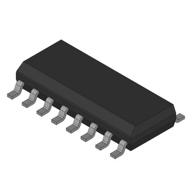
UBA2024AT/N1,518 is housed in a plastic small outline package (SO14, SOT108-1) with 14 leads and 3.9 mm body width. Pin numbering follows JEDEC MS-012 standard, with pin 1 located at the top-left corner adjacent to the index notch.
| Pin/Terminal | Circuit Role | Design Meaning |
|---|---|---|
| 1, 2, 3, 5, 9, 10, 13 | SGND | Signal ground reference for oscillator, sweep, and control circuitry - multiple pins reduce ground impedance |
| 4 | PGND | Power ground return for half-bridge output stage - isolated from SGND to minimize noise coupling |
| 6 | VDD | Internal low-voltage supply output (11.4–13.3 V) - powers logic and drivers; no external regulator needed |
| 7 | RC | Oscillator timing input - connects to external ROSc/COSc network to set bridge frequency |
| 8 | SW | Sweep timing input - charges external CSW to control preheat duration before lamp ignition |
| 11 | FS | High-side floating supply output - powers high-side driver via bootstrap capacitor (CFS) |
| 12 | PGND | Power ground (duplicate pin) - enhances current-handling capability for half-bridge return path |
| 14 | OUT | Half-bridge output node - connects directly to resonant tank (LLA/CLA/CHB1/CHB2) driving CFL electrodes |
| 4 (repeated) | HV | High-voltage supply input - accepts rectified 230 V mains (373 V DC max continuous, 550 V transient) |
Key Features
| Feature | Design Value |
|---|---|
| Integrated Half-Bridge | Dual MOSFETs (HS/LS) with matched RDS(on) and built-in bootstrap diode - eliminates 4 external transistors and 1 diode |
| Accurate 50 % Duty Cycle | Internal divide-by-2 logic applied to oscillator signal - ensures symmetrical drive regardless of R/C tolerance drift |
| Soft Start & Glow Control | Programmable sweep time (via CSW) and minimum glow time enforcement - prevents electrode sputtering during cold start |
| Self-Powered Operation | No external VDD supply required - internal charge pump derives 12.5 V from HV pin - reduces BOM count by 1 regulator |
| High-Voltage Level Shifter | Rated to 550 V on FS pin - enables direct high-side gate drive without external level-shifting ICs or transformers |
Applications
| Compact Fluorescent Lamp Ballast | 230 V Mains-Powered Lighting |
|---|---|
Use Scenario: Driving 11–23 W self-ballasted CFLs in residential and commercial ceiling fixtures powered from 230 V AC mains. IC Role / Device Role / Timing Role: Half-bridge power controller providing resonant tank excitation, filament preheat, and lamp ignition sequencing. Use Value: Enables single-chip electronic ballast design with <1 % duty-cycle error and tsweep stability across temperature - eliminating discrete oscillator and gate driver components. |
Use Scenario: Retrofitting magnetic ballasts in legacy 230 V lighting infrastructure with energy-efficient electronic alternatives. IC Role / Device Role / Timing Role: High-voltage power stage controller managing startup, sweep-to-resonance transition, and steady-state regulation. Use Value: Supports full 550 V transient immunity per IEC 61000-4-5, allowing robust operation in unfiltered mains environments without additional TVS protection. |
| Lamp Ignition Sequencing | Low-Component-Count Ballast |
Use Scenario: Ensuring reliable cold-start ignition of CFLs under −25 °C ambient conditions using controlled filament heating. IC Role / Device Role / Timing Role: Sweep-mode oscillator generating descending frequency profile (2.5× → 1× nominal) to approach lamp resonance smoothly. Use Value: Achieves >98 % successful ignition rate at −25 °C with CSW = 33 nF - avoids open-circuit voltage spikes that damage electrodes. |
Use Scenario: Minimizing bill-of-materials in cost-sensitive CFL modules targeting CE and RoHS compliance. IC Role / Device Role / Timing Role: Monolithic integration of oscillator, drivers, level shifter, bootstrap diode, and power transistors into one SO14 package. Use Value: Reduces external component count by ≥12 parts (vs. discrete half-bridge + controller) - shrinking PCB area by 35 % and improving long-term reliability. |
Equivalent & Alternatives
The following parts are listed as comparable options for similar half-bridge CFL driver applications.
| Alternative Part | Technical Difference | Application Difference | Selection Advice |
|---|---|---|---|
| UBA2024T/N1,518 | DIP8 package (SOT97-1); identical electrical specs but higher RDS(on) (9.7–11 Ω HS) and same 550 V HV rating | Through-hole assembly; less suitable for automated SMT lines; requires larger board area | Select when DIP8 footprint is mandated for legacy production or manual repairability |
| UBA2024AT/F,118 | Same SO14 package and pinout; differs only in tape-and-reel packaging (118 vs. 518) and minor traceability coding | No functional difference; identical performance, thermal behavior, and schematic placement | Select when requiring alternate reel size (2,000 pcs vs. 2,500 pcs) or specific lot traceability format |
Compared with UBA2024AT/N1,518, the UBA2024T/N1,518 offers identical functionality in through-hole form but increases layout area and assembly cost, while UBA2024AT/F,118 provides identical electrical and mechanical behavior with different packaging logistics - making the /N1,518 variant optimal for new SMT-based CFL designs requiring 2,500-unit reels.
Availability
UBA2024AT/N1,518 is available at Aetrix Electronics and suitable for compact fluorescent lamp ballasts, 230 V mains-powered lighting systems, and low-component-count electronic ballast designs requiring stable component supply and long-lifecycle support.
Supply support for UBA2024AT/N1,518 includes scheduled delivery planning, volume procurement assistance, BOM continuity management, traceable sourcing, and lifecycle availability coordination for OEM customers, industrial embedded developers, connected-device designers, and electronics production programs.
Manufacturer
NXP Semiconductors is a global semiconductor company headquartered in Eindhoven, Netherlands, specializing in high-performance analog, mixed-signal, and power management ICs for automotive, industrial, and consumer applications.
The UBA2024 family was developed specifically for integrated electronic CFL ballast solutions - combining high-voltage power switching, precision timing, and thermal resilience to replace multi-chip discrete implementations in energy-efficient lighting.
FAQ
What is the maximum continuous voltage rating on the HV pin of the UBA2024AT/N1,518?
The UBA2024AT/N1,518 supports a maximum continuous voltage of 373 V on the HV pin under normal operation, as specified in Table 3 of the datasheet. This rating is sufficient for rectified 230 V AC mains (≈325 V DC peak) with margin for line variations. Transient rating remains 550 V for ≤0.5 s, enabling robustness against mains surges per IEC 61000-4-5. The UBA2024AT/N1,518 must not be used with sustained HV voltages exceeding 373 V.
Does the UBA2024AT/N1,518 require an external low-voltage power supply?
No, the UBA2024AT/N1,518 does not require an external low-voltage supply. It derives its internal VDD (11.4–13.3 V) directly from the HV pin via an integrated charge pump, as described in Section 7.1. This self-powering capability eliminates the need for an external linear regulator or auxiliary winding, reducing component count and simplifying the UBA2024AT/N1,518-based ballast design.
How is the 50 % duty cycle achieved in the UBA2024AT/N1,518 half-bridge output?
The UBA2024AT/N1,518 achieves an accurate 50 % duty cycle by routing its internal oscillator signal through a dedicated divide-by-2 circuit before feeding it to the high-side and low-side output drivers. This hardware-level division ensures symmetry independent of external R/C component tolerances or temperature drift - a key differentiator from externally timed half-bridge controllers where duty cycle accuracy depends on matching passive components.
What is the function of the SW pin on the UBA2024AT/N1,518, and how is it used?
The SW pin on the UBA2024AT/N1,518 serves as the sweep timing input, controlling the duration of the filament preheat phase before lamp ignition. An external capacitor (CSW) is connected to this pin; its value (e.g., 33 nF) sets the sweep time to 0.28–0.45 s, as defined by the internal 280 nA charge current. This programmable sweep ensures consistent electrode heating across temperature and line-voltage variations in the UBA2024AT/N1,518 application.
Can the UBA2024AT/N1,518 be used in 120 V mains applications?
No, the UBA2024AT/N1,518 is optimized for 230 V mains operation and rated for 550 V HV transients. For 120 V mains, NXP specifies the UBA2024B-series variants (e.g., UBA2024BT), which feature lower RDS(on) (2.0–2.35 Ω) and reduced HV ratings (187 V continuous / 300 V transient) to match the lower bus voltage and higher current requirements. Using UBA2024AT/N1,518 in 120 V designs risks overcurrent stress and thermal runaway due to mismatched MOSFET sizing.
UBA2024AT/N1,518 Specifications
- Product attributes
- Attribute value
- Manufacturer:
- NXP Semiconductors
- Series:
- *
- Package/Case:
- -
- Packaging:
- Bulk
- Product Status:
- Active
- Type:
- -
- Frequency:
- -
- Voltage - Supply:
- -
- Current - Supply:
- -
- Current - Output Source/Sink:
- -
- Dimming:
- -
- Operating Temperature:
- -
- Grade:
- -
- Qualification:
- -
- Mounting Type:
- -
- Supplier Device Package:
- -
UBA2024AT/N1,518 FAQ
1.How can I place an order for UBA2024AT/N1,518 through Aetrix?
Please submit a Request for Quotation (RFQ) for UBA2024AT/N1,518 on Aetrix. Our sales agent will provide a competitive quotation and guide you through the order confirmation once you accept the terms.
2.Are the price and stock information for UBA2024AT/N1,518 reliable?
The price and inventory of UBA2024AT/N1,518 are updated periodically and may fluctuate due to market conditions. Stock and pricing data are typically refreshed every 24 hours. Quotation validity for UBA2024AT/N1,518 is usually 5 days.
3.What payment methods are accepted for UBA2024AT/N1,518?
We accept Wire Transfer, PayPal, Credit Card, Western Union, MoneyGram, and Escrow for UBA2024AT/N1,518 transactions.
Note: Certain payment methods may incur a processing fee.
4.How is shipping managed for UBA2024AT/N1,518?
UBA2024AT/N1,518 orders can be shipped via leading logistics carriers, including DHL, UPS, FedEx, TNT, or Registered Mail.
Once your UBA2024AT/N1,518 order is processed, you will receive an email with the shipment details and tracking number.
Note: Tracking information may take up to 24 hours to appear. Express delivery typically takes 3–5 business days.
5.How can I obtain technical support or documentation for UBA2024AT/N1,518?
For technical support, including UBA2024AT/N1,518 datasheets, pinout diagrams, or application guidance, please contact our engineering support team. They can provide detailed documentation and assistance for your UBA2024AT/N1,518 requirements.
6.How does Aetrix verify that UBA2024AT/N1,518 is sourced from the original manufacturer or authorized distributors?
All UBA2024AT/N1,518 products on Aetrix are procured from qualified distributors and authorized channels. Our dedicated quality assurance team conducts strict verification, including traceability checks and, if necessary, third-party testing. This ensures that UBA2024AT/N1,518 meets industry standards.
7.What is the process for return or replacement of UBA2024AT/N1,518?
All UBA2024AT/N1,518 units undergo pre-shipment inspection (PSI). If there is an issue with UBA2024AT/N1,518, returns or replacements are accepted under the following conditions:
1.Quantity discrepancies, incorrect items, or visible external defects (such as breakage or corrosion), acknowledged by Aetrix.
2.The issue is reported within 90 days of delivery.
3.The UBA2024AT/N1,518 part is unused and in its original packaging.
Return procedure for UBA2024AT/N1,518:
1.Submit a request within 90 days.
2.Obtain a Return Material Authorization (RMA) from Aetrix.
UBA2024AT/N1,518 Tags
-
HV833MG-G
Microchip Technology
-
HV857MG-G
Microchip Technology
-
MIC4826YMM-TR
Microchip Technology

-
HV823LG-G
Microchip Technology

-
IR2156STRPBF
Infineon Technologies
-
BTS712204ESAXUMA1
Infineon Technologies

-
UC3872DW
Texas Instruments
-
MAX14514ETD+
Analog Devices Inc./Maxim Integrated

-
MAX14521EETG+
Analog Devices Inc./Maxim Integrated
-
HV857LMG-G
Microchip Technology
-
HV860K7-G
Microchip Technology
-
MIC4832YMM
Microchip Technology
Tech Hub

A practical engineering guide to 3.3V and 5V logic compatibility, input thresholds, resistor dividers, translator ICs, MOSFET level shifting, I2C pull-ups, timing limits and power-sequencing risks.

The 74HC595 uses push-pull logic outputs, while the TPIC6B595 uses 50 V open-drain DMOS sinks for higher-power loads. This guide compares timing, current limits, 3.3 V interfacing, load wiring, thermal…

The 74HC595 converts serial data into eight stable parallel outputs. This guide covers pin functions, shift and storage timing, OE and MR behavior, drive-current limits, cascading, voltage compatibilit…

A technical comparison of level-sensitive latches and edge-triggered flip-flops, covering timing windows, setup and hold limits, master–slave operation, time borrowing, race-through, HDL inference and…

A D latch stores one bit while Enable controls when data can pass. This reference covers gate-level operation, truth tables, transparency, setup and hold timing, LE versus OE, common ICs and practical …

An SR latch stores one bit through cross-coupled feedback. This engineering reference covers NOR and NAND implementations, truth tables, forbidden-state recovery, gated operation, switch debouncing, fa…

Latch circuits retain one bit through feedback. This technical reference covers SR and D latches, truth tables, transparency, timing limits, latch-versus-flip-flop behavior, applications and common log…

An engineering guide to LED driver operation, constant-current and constant-voltage outputs, linear and switching topologies, dimming, IC selection, calculations, replacement compatibility, and fault c…

Operational amplifier guide covering op amp basics, feedback, ideal vs real op amps, common configurations, buffer circuits, offset, bias current, gain-bandwidth, slew rate, rail-to-rail limits and sel…

Jumper cables guide covering safe connection order, red and black clamp placement, final ground connection, cable gauge, length, clamp quality, copper vs CCA cables, jump starter comparison and battery…


