
 My Inquiry
 My Account


Texas Instruments UC3854QG3
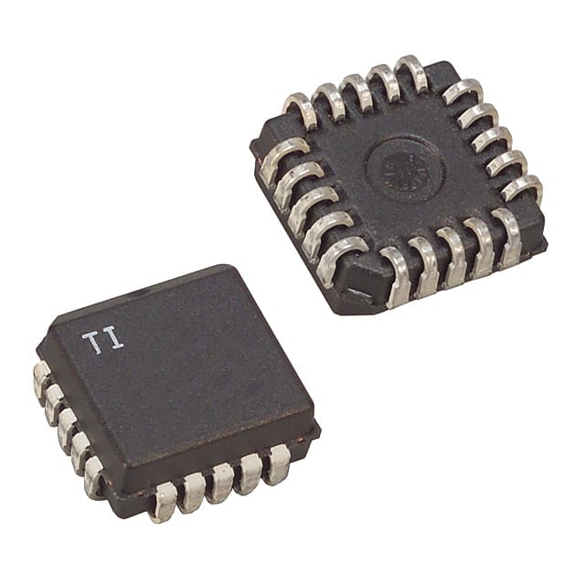
- Part No.:
- UC3854QG3
- Manufacturer:
- Texas Instruments
- Category:
- PFC (Power Factor Correction)
- Package:
- 20-LCC (J-Lead)
- Datasheet:
-
 UC3854QG3.pdf
- Description:
- IC PFC CTR AVERAGE 200KHZ 20PLCC
- Quantity:
- Payment:

- Shipping:

Inventory:4,312
Please send an inquiry. Send us your inquiry, and we will respond immediately.
Product details
Overview
UC3854QG3 from Texas Instruments is a high-power-factor preregulator controller IC implementing average current-mode control for boost PFC stages. It delivers 0.99 power factor, <5% line-current distortion, and fixed-frequency PWM drive up to 62 kHz with 7.5-V precision reference and 1-A totem-pole gate driver - used in offline AC-to-DC converters delivering 400 VDC output.
For engineers reviewing the UC3854QG3 datasheet, UC3854QG3 pinout, UC3854QG3 application, or UC3854QG3 equivalent, key selection criteria include its average current-mode architecture, VRMS feedforward capability, IAC current-input multiplier interface, and SOIC-16 package compatibility with industrial and telecom power supplies.
Technical Context
The UC3854QG3 integrates a voltage amplifier (100 dB gain, 0.5–5.8 V swing), analog multiplier/divider with IAC current input and VRMS feedforward, and a wideband current amplifier (1 MHz bandwidth, ±4 mV offset) to enforce sinusoidal line current without slope compensation. Its oscillator uses RSET/CT to set frequency (46–118 kHz), and GTDRV provides clamped 14.5-V, 1-A gate drive with 35 ns rise/fall time.
It operates across 0°C to 70°C junction temperature, requires VCC ≥17 V for startup (16 V typical turn-on), and features ENA logic enable, soft-start via SS pin, and PKLMT overcurrent shutdown triggered at 0 V. The device maintains active voltage/current amplifier outputs even during disable cycles, preserving loop stability.
Key Specifications
| Parameter | Value and Actual Design Meaning |
|---|---|
| VCC Operating Range | 10–20 V - supports stable operation with standard 15–18 V bias rails; UVLO thresholds at 16 V (on) / 10 V (off) |
| Oscillator Frequency | 46–62 kHz (RSET = 15 kΩ) - sets fixed switching frequency for EMI-controlled boost stage design |
| VREF Output | 7.5 V ±0.15 V - precision internal reference powering external circuitry; 10 mA sink/source capability |
| GTDRV Output | 14.5 V max, 1 A peak - drives N-channel MOSFET gates directly; internally clamped to prevent overvoltage |
| Current Amplifier BW | 1 MHz typical - enables accurate average current sensing without noise-induced instability |
| Power Factor | 0.99 - achieved via feedforward VRMS input and analog multiplier-based current command synthesis |
| Line Distortion | <5% THD - meets EN61000-3-2 Class D requirements for >75 W equipment |
Pinout & Package
UC3854QG3 is housed in a 16-pin SOIC package (7.50 mm × 10.30 mm body size) with standard JEDEC MS-012AC footprint and 1.27 mm pitch.
| Pin/Terminal | Circuit Role | Design Meaning |
|---|---|---|
| GND (Pin 1) | Ground reference | Common return for VCC, VREF bypassing and CT discharge path; requires short, direct 0.1 µF ceramic connection |
| PKLMT (Pin 2) | Peak current limit input | 0 V threshold shutdown input - connects to negative side of sense resistor to terminate PWM on overcurrent |
| CAOUT (Pin 3) | Current amplifier output | Drives PWM comparator; swings to near GND to force zero duty cycle; remains active during disable |
| ISENSE (Pin 4) | Current-sense inverting input | Accepts differential current-sense signal down to –0.3 V; paired with MULTOUT for noise-rejecting configuration |
| MULTOUT (Pin 5) | Multiplier output / current-sense + | High-impedance node combining analog multiplier output and current amplifier non-inverting input |
| IAC (Pin 6) | AC current input | 6 V-biased current input for line voltage waveform sampling; enables low-distortion multiplier operation |
| VAOUT (Pin 7) | Voltage amplifier output | Regulates boost output voltage; clamped to ~5.8 V; stays charged during soft-start or disable events |
| VRMS (Pin 8) | RMS line voltage feedforward | 1.5–3.5 V input compensating for line variations - improves transient response and reduces output ripple |
| VREF (Pin 9) | 7.5 V reference output | Stable reference for feedback dividers and peripheral circuits; disabled when ENA = low or VCC undervoltage |
| ENA (Pin 10) | Enable logic input | 2.55 V threshold; releases SS clamp and enables oscillator/VREF; not intended for high-speed PWM shutdown |
| VSENSE (Pin 11) | Voltage feedback input | Inverting input to voltage amplifier; connects to resistive divider from 400 VDC output |
| RSET (Pin 12) | Oscillator/multiplier set | Resistor to GND programs oscillator charging current and maximum multiplier output (IMULTOUT ≤ 3.75 V/RRSET) |
| SS (Pin 13) | Soft-start timing | Internally sourced 14 mA current charges external capacitor; controls ramp-up of voltage loop reference |
| CT (Pin 14) | Oscillator timing | Capacitor to GND sets PWM frequency; CT ramp amplitude 4.9–5.9 V peak-to-valley |
| VCC (Pin 15) | Supply voltage input | 17–20 V required for normal operation; bypassed directly to GND with ≥0.1 µF ceramic |
| GTDRV (Pin 16) | Gate driver output | Totem-pole MOSFET driver; 1 A peak, 35 ns edge speed; series gate resistor ≥5 Ω recommended |
Key Features
| Feature | Design Value |
|---|---|
| Average current-mode control | Enables stable, low-distortion sinusoidal line current without slope compensation across CCM/DCM transitions |
| Feedforward VRMS input | Compensates for input line voltage variation in real time, reducing output voltage deviation during transients |
| Low-noise analog multiplier | Uses IAC current input and VRMS feedforward to generate precise current command with <5% THD |
| Integrated 7.5 V reference | Provides stable, temperature-compensated reference for feedback networks and external circuitry (10 mA capable) |
| 1-A totem-pole gate driver | Directly drives power MOSFET gates with fast edges and internal 15 V clamp - eliminates need for external level shifters |
| Soft-start with SS pin | Programmable ramp-up of voltage loop reference prevents inrush current and output overshoot at startup |
Applications
| Server Power Supply | Medical AC-DC Adapter |
|---|---|
Use Scenario: 80 PLUS Titanium-certified 1.5 kW server PSU requiring >0.99 PF and <5% THD across universal 90–264 VAC input. IC Role / Device Role / Timing Role: UC3854QG3 serves as the front-end active PFC controller, generating fixed-frequency PWM to regulate boost converter output at 400 VDC while enforcing sinusoidal line current. Use Value: Enables compliance with EN61000-3-2 Class D and achieves measured 0.999 PF / 3.81% THD at full load - critical for datacenter energy efficiency mandates. | Use Scenario: Isolated 300 W medical-grade AC-DC adapter for diagnostic imaging equipment operating from 100–240 VAC, 50/60 Hz. IC Role / Device Role / Timing Role: UC3854QG3 implements average current-mode PFC in continuous conduction mode boost stage, feeding isolated DC-DC stage with stabilized 400 VDC bus. Use Value: Delivers ultra-low harmonic distortion (<4%) and robust line regulation via VRMS feedforward - ensuring EMC compliance and stable downstream DC-DC operation. |
| Industrial UPS System | White Goods Motor Drive |
Use Scenario: Online double-conversion UPS with 2 kVA rating, requiring seamless transfer, low input distortion, and wide input voltage range (75–275 VAC). IC Role / Device Role / Timing Role: UC3854QG3 acts as the bidirectional PFC controller in rectifier/inverter stage, maintaining unity PF during battery charging and grid support modes. Use Value: Supports world-wide operation without hardware switches and handles 50–400 Hz line frequencies - essential for global deployment and generator-backed operation. | Use Scenario: Variable-speed compressor drive in premium refrigerator using universal AC input and brushless DC motor. IC Role / Device Role / Timing Role: UC3854QG3 controls boost PFC stage to supply clean 400 VDC bus for inverter stage, enabling high-efficiency motor control under varying line conditions. Use Value: Achieves <5% line-current distortion while supporting low-startup supply current (2 mA OFF) - extends component life and reduces audible noise in residential environments. |
Equivalent & Alternatives
The following parts are listed as comparable options for similar active power factor correction applications.
| Alternative Part | Technical Difference | Application Difference | Selection Advice |
|---|---|---|---|
| UCC28511DR | Higher current amplifier bandwidth (5 MHz vs 1 MHz); lower VCC UVLO (10.5 V); no VRMS feedforward | Optimized for higher-frequency designs (>200 kHz); lacks line-voltage feedforward for tight output regulation | Prefer UCC28511DR for compact, high-frequency PFC where VRMS compensation is not required |
| ICE3PCS01G | Fixed-frequency CCM/DCM hybrid control; integrated 650 V startup circuit; no external RSET/CT tuning | Designed for cost-sensitive consumer appliances; lacks programmable oscillator and analog multiplier flexibility | Choose ICE3PCS01G for simplified BOM and embedded startup in white goods with fixed-line applications |
Compared with UCC28511DR and ICE3PCS01G, the UC3854QG3 offers superior line-voltage feedforward (VRMS), fully programmable oscillator, and proven average current-mode stability - making it preferred for high-accuracy, wide-input industrial and telecom PFC designs where THD <4% and dynamic line regulation are critical.
Availability
UC3854QG3 is available at Aetrix Electronics and suitable for offline AC-to-DC converters, medical power supplies, and industrial UPS systems requiring stable component supply, long-term lifecycle support, and consistent parametric performance across temperature.
Supply support for UC3854QG3 includes scheduled delivery planning, volume procurement assistance, BOM continuity management, traceable sourcing, and lifecycle availability coordination for OEM customers, industrial embedded developers, connected-device designers, and electronics production programs.
Manufacturer
Texas Instruments is a global semiconductor company designing analog ICs, embedded processors, and power management solutions for industrial, automotive, and communications markets.
The UC3854QG3 belongs to TI's legacy UCx854 family of high-power-factor preregulator controllers - engineered specifically for average current-mode boost PFC in universal-input AC-DC power supplies meeting EN61000-3-2.
FAQ
What is the operating temperature range for the UC3854QG3?
The UC3854QG3 is rated for 0°C to 70°C junction temperature. This commercial-grade specification aligns with its SOIC-16 packaging and targets industrial and telecom power supply applications where ambient temperatures remain within controlled enclosures. Derating is required above 70°C ambient, and thermal design must account for RθJA = 71.5°C/W in SOIC package.
Does the UC3854QG3 support discontinuous conduction mode (DCM) operation?
Yes, the UC3854QG3 supports both continuous and discontinuous conduction modes without performance degradation. Its average current-mode control architecture ensures stable, low-distortion line current in either mode - unlike peak current-mode controllers that require slope compensation in DCM. This flexibility simplifies design across varying load and line conditions.
How does the VRMS pin improve regulation in the UC3854QG3?
The VRMS pin on the UC3854QG3 accepts a voltage proportional to RMS input line voltage (1.5–3.5 V). This feedforward signal squares and scales the multiplier's output, dynamically adjusting the current command to maintain constant output power despite line fluctuations - reducing output voltage deviation by up to 70% during 10% line sags.
What is the purpose of the PKLMT pin on the UC3854QG3?
The PKLMT pin on the UC3854QG3 provides cycle-by-cycle peak current limiting. With a 0 V threshold, it connects to the negative side of the current-sense resistor. When the sensed voltage drops below ground (indicating overcurrent), the PWM output shuts off immediately - protecting the power MOSFET and boost inductor during fault conditions or startup surges.
Can the UC3854QG3 be used with a 3-phase input?
Yes, the UC3854QG3 can be applied in three-phase PFC topologies, including three-phase boost or Vienna rectifier configurations. Its wide input voltage range (75–275 VAC), 50–400 Hz line frequency support, and analog multiplier architecture allow implementation with appropriate front-end rectification and signal conditioning - documented in TI application reports SLUA146 and SLUP145.
UC3854QG3 Specifications
- Product attributes
- Attribute value
- Manufacturer:
- Texas Instruments
- Series:
- -
- Package/Case:
- 20-LCC (J-Lead)
- Packaging:
- Tube
- Product Status:
- Obsolete
- Mode:
- Average Current
- Frequency - Switching:
- 200kHz
- Current - Startup:
- 1.5 mA
- Voltage - Supply:
- 14.5V ~ 30V
- Operating Temperature:
- 0°C ~ 70°C
- Grade:
- -
- Qualification:
- -
- Mounting Type:
- Surface Mount
- Supplier Device Package:
- 20-PLCC (9x9)
UC3854QG3 FAQ
1.How can I place an order for UC3854QG3 through Aetrix?
Please submit a Request for Quotation (RFQ) for UC3854QG3 on Aetrix. Our sales agent will provide a competitive quotation and guide you through the order confirmation once you accept the terms.
2.Are the price and stock information for UC3854QG3 reliable?
The price and inventory of UC3854QG3 are updated periodically and may fluctuate due to market conditions. Stock and pricing data are typically refreshed every 24 hours. Quotation validity for UC3854QG3 is usually 5 days.
3.What payment methods are accepted for UC3854QG3?
We accept Wire Transfer, PayPal, Credit Card, Western Union, MoneyGram, and Escrow for UC3854QG3 transactions.
Note: Certain payment methods may incur a processing fee.
4.How is shipping managed for UC3854QG3?
UC3854QG3 orders can be shipped via leading logistics carriers, including DHL, UPS, FedEx, TNT, or Registered Mail.
Once your UC3854QG3 order is processed, you will receive an email with the shipment details and tracking number.
Note: Tracking information may take up to 24 hours to appear. Express delivery typically takes 3–5 business days.
5.How can I obtain technical support or documentation for UC3854QG3?
For technical support, including UC3854QG3 datasheets, pinout diagrams, or application guidance, please contact our engineering support team. They can provide detailed documentation and assistance for your UC3854QG3 requirements.
6.How does Aetrix verify that UC3854QG3 is sourced from the original manufacturer or authorized distributors?
All UC3854QG3 products on Aetrix are procured from qualified distributors and authorized channels. Our dedicated quality assurance team conducts strict verification, including traceability checks and, if necessary, third-party testing. This ensures that UC3854QG3 meets industry standards.
7.What is the process for return or replacement of UC3854QG3?
All UC3854QG3 units undergo pre-shipment inspection (PSI). If there is an issue with UC3854QG3, returns or replacements are accepted under the following conditions:
1.Quantity discrepancies, incorrect items, or visible external defects (such as breakage or corrosion), acknowledged by Aetrix.
2.The issue is reported within 90 days of delivery.
3.The UC3854QG3 part is unused and in its original packaging.
Return procedure for UC3854QG3:
1.Submit a request within 90 days.
2.Obtain a Return Material Authorization (RMA) from Aetrix.
UC3854QG3 Tags

-
ICE2PCS01GXUMA1
Infineon Technologies

-
NCP1654BD133R2G
onsemi
-
MC33262DR2G
onsemi
-
ICE3PCS03GXUMA1
Infineon Technologies
-
NCP1631DR2G
onsemi

-
L4981BD013TR
STMicroelectronics
-
UCC28070DWR
Texas Instruments

-
UCC28070PWR
Texas Instruments

-
UC3854DWTR
Texas Instruments
-
L4981AD013TR
STMicroelectronics

-
UCC2817D
Texas Instruments
-
UC2854BDWTR
Texas Instruments
Tech Hub

A practical engineering guide to 3.3V and 5V logic compatibility, input thresholds, resistor dividers, translator ICs, MOSFET level shifting, I2C pull-ups, timing limits and power-sequencing risks.

The 74HC595 uses push-pull logic outputs, while the TPIC6B595 uses 50 V open-drain DMOS sinks for higher-power loads. This guide compares timing, current limits, 3.3 V interfacing, load wiring, thermal…

The 74HC595 converts serial data into eight stable parallel outputs. This guide covers pin functions, shift and storage timing, OE and MR behavior, drive-current limits, cascading, voltage compatibilit…

A technical comparison of level-sensitive latches and edge-triggered flip-flops, covering timing windows, setup and hold limits, master–slave operation, time borrowing, race-through, HDL inference and…

A D latch stores one bit while Enable controls when data can pass. This reference covers gate-level operation, truth tables, transparency, setup and hold timing, LE versus OE, common ICs and practical …

An SR latch stores one bit through cross-coupled feedback. This engineering reference covers NOR and NAND implementations, truth tables, forbidden-state recovery, gated operation, switch debouncing, fa…

Latch circuits retain one bit through feedback. This technical reference covers SR and D latches, truth tables, transparency, timing limits, latch-versus-flip-flop behavior, applications and common log…

An engineering guide to LED driver operation, constant-current and constant-voltage outputs, linear and switching topologies, dimming, IC selection, calculations, replacement compatibility, and fault c…

Operational amplifier guide covering op amp basics, feedback, ideal vs real op amps, common configurations, buffer circuits, offset, bias current, gain-bandwidth, slew rate, rail-to-rail limits and sel…

Jumper cables guide covering safe connection order, red and black clamp placement, final ground connection, cable gauge, length, clamp quality, copper vs CCA cables, jump starter comparison and battery…


