
 My Inquiry
 My Account


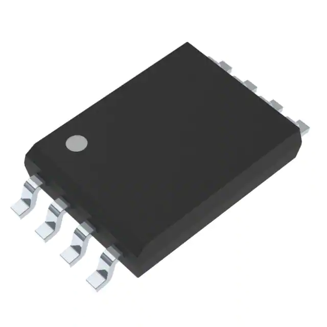
Texas Instruments UCC21540AQDWKRQ1
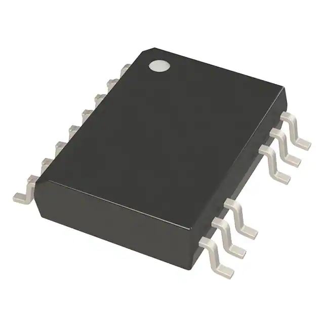
- Part No.:
- UCC21540AQDWKRQ1
- Manufacturer:
- Texas Instruments
- Category:
- Isolators - Gate Drivers
- Package:
- 14-SOIC (0.295", 7.50mm Width)
- Datasheet:
-
 UCC21540AQDWKRQ1.pdf
- Description:
- DGTL ISO 5.7KV 2CH GT DVR 14SOIC
- Quantity:
- Payment:

- Shipping:

Inventory:4,807
Please send an inquiry. Send us your inquiry, and we will respond immediately.
Product details
Overview
UCC21540AQDWKRQ1 from Texas Instruments is an AEC-Q100 Grade 1 qualified reinforced-isolation dual-channel gate driver with 4-A peak source / 6-A peak sink current, 5-V VDD UVLO threshold, and 125 V/ns CMTI - designed for driving Si MOSFETs, IGBTs, and GaN transistors in high-reliability automotive traction inverters and on-board chargers.
For engineers reviewing the UCC21540AQDWKRQ1 datasheet, UCC21540AQDWKRQ1 pinout, UCC21540AQDWKRQ1 application, or UCC21540AQDWKRQ1 equivalent, this page delivers verified functional safety documentation support, SOIC-14 DWK package layout guidance, dead-time programmability via external resistor, and confirmed compatibility with HEV/EV battery charger topologies requiring >5.7-kVRMS isolation and –40°C to +150°C junction operation.
Technical Context
The UCC21540AQDWKRQ1 implements a capacitive reinforced isolation barrier separating input logic (VCCI/GND) from two independent output channels (VDDA/VSSA and VDDB/VSSB), each with dedicated 4-A/6-A drive strength and programmable dead time. Its input stage features TTL/CMOS-compatible thresholds with internal pull-down, while outputs support active pull-down during VDD loss.
Functional modes include dual low-side, dual high-side, or half-bridge configuration - selected by external routing - with integrated disable (DIS) and dead-time (DT) pins enabling system-level fault response and shoot-through prevention. All supplies feature UVLO with hysteresis: 5.7–6.3 V rising/falling for VDDA/VDDB and 2.55–2.85 V for VCCI.
Key Specifications
| Parameter | Value and Actual Design Meaning |
|---|---|
| VDD UVLO Threshold | 6.0 V rising (min), enables reliable turn-on only after secondary supply stabilizes above automotive 12-V rail derating margin |
| Peak Output Current | 4 A source / 6 A sink per channel - sufficient to drive 1200-V SiC MOSFET gates at >100 kHz with <16 ns rise/fall times |
| CMTI | >125 V/ns - maintains signal integrity in noisy motor drive environments with fast dv/dt transients across isolation barrier |
| Propagation Delay | 33 ns typical - ensures precise timing alignment between high- and low-side switches in phase-shifted or synchronous rectifier topologies |
| Pulse-Width Distortion | 6 ns max - guarantees matched switching edges critical for minimizing dead-time uncertainty in space-vector PWM control |
| Junction Temperature Range | –40°C to +150°C - validated for under-hood automotive applications including traction inverter gate driver stages |
| Isolation Rating | 5.7 kVRMS reinforced - meets IEC 60747-17 and UL 1577 requirements for functional safety in ASIL-B/C systems |
Pinout & Package
UCC21540AQDWKRQ1 is housed in a 14-pin SOIC (DWK) package with gull-wing leads, optimized for creepage/clearance compliance (>8 mm) and thermal performance (RθJA = 74.1°C/W). The package integrates reinforced isolation with internal double insulation (DTI >17 µm) and CTI >600 V.
| Pin/Terminal | Circuit Role | Design Meaning |
|---|---|---|
| INA, INB | Input logic signals | TTL/CMOS-compatible inputs with internal pull-down; tied low if unused to prevent noise-induced switching |
| DIS | Global disable control | Active-high shutdown of both outputs within ≤2 µs - used for emergency stop or overcurrent lockout |
| DT | Dead-time programming | Resistor-connected pin (DT = 10 × RDT kΩ ns); bypassed with ≤1 nF capacitor for EMI immunity |
| VCCI | Primary-side supply | 3–18 V input supply with 2.7 V UVLO hysteresis; pins 3 and 8 internally shorted for robust decoupling |
| VDDA, VDDB | Secondary-side driver supplies | 6.5–25 V per channel; 6.0 V UVLO rising threshold ensures gate drive only when output rail is stable |
| OUTA, OUTB | Gate drive outputs | 4-A/6-A capable outputs with active pull-down (1.6–2.0 V clamp) during VDD loss - prevents shoot-through |
| VSSA, VSSB | Secondary-side grounds | Independent ground references per channel - essential for floating high-side drive in half-bridge configurations |
| GND | Primary-side ground | Reference for all input-side signals; must be isolated from VSSA/VSSB by PCB layout and transformer design |
Key Features
| Feature | Design Value |
|---|---|
| Reinforced Isolation Barrier | 5.7-kVRMS rating with >125 V/ns CMTI - eliminates need for external optocouplers or pulse transformers in ASIL-B systems |
| Programmable Dead Time | Adjustable 80–600 ns via single external resistor (RDT) - enables precise shoot-through prevention without MCU intervention |
| Active Pull-Down Protection | Clamps outputs to ≤2.0 V during VDDA/VDDB undervoltage - prevents partial turn-on of power devices during brownout |
| AEC-Q100 Grade 1 Qualification | Validated for –40°C to +150°C operation with full automotive temperature cycling and HTOL testing - suitable for traction inverter placement |
| Integrated Disable Function | Single-pin global shutdown with sub-2-µs response - supports hardware-level fault propagation in ISO 26262-compliant architectures |
Applications
| Automotive Traction Inverter | On-Board Charger (OBC) |
|---|---|
Use Scenario: Driving high-side and low-side SiC MOSFETs in a 3-phase inverter for EV motor control under under-hood thermal stress. IC Role / Device Role / Timing Role: Dual-channel isolated gate driver providing synchronized, shoot-through-protected switching with <6 ns pulse-width distortion. Use Value: Enables 150°C junction operation with reinforced isolation, eliminating external level shifters and reducing BOM count by 3 components per phase. |
Use Scenario: Controlling interleaved LLC resonant converter stages in 11-kW OBC designs with bidirectional AC/DC and DC/DC conversion. IC Role / Device Role / Timing Role: Half-bridge configured driver delivering 4-A/6-A gate current with programmable dead time to manage ZVS transitions. Use Value: Supports >96% efficiency at full load by minimizing switching losses through precise 33-ns propagation delay and matched channel timing. |
| Industrial Motor Drive | Renewable Energy Inverter |
Use Scenario: Gate driving 1200-V IGBT modules in HVAC compressors and industrial pumps operating in harsh factory environments. IC Role / Device Role / Timing Role: Dual low-side driver with 5.7-kVRMS isolation and 125 V/ns CMTI for noise-immune operation near high-power busbars. Use Value: Eliminates ground-loop interference and enables direct connection to microcontroller GPIOs without additional level-shifting circuitry. |
Use Scenario: Driving high-voltage Si MOSFETs in string-level solar inverters exposed to wide ambient temperature swings and lightning-induced transients. IC Role / Device Role / Timing Role: Reinforced-isolated dual driver supporting 150°C junction operation and 8000-VPK transient surge immunity per IEC 62368-1. Use Value: Meets IEC 61000-4-5 Level 4 surge immunity requirements without external TVS clamping on gate drive lines. |
Equivalent & Alternatives
The following parts are listed as comparable options for similar dual-channel isolated gate driver applications.
| Alternative Part | Technical Difference | Application Difference | Selection Advice |
|---|---|---|---|
| UCC21540QDWKRQ1 | 8-V VDD UVLO threshold vs. 6-V for UCC21540AQDWKRQ1; identical pinout, drive strength, and isolation specs | Better suited for 24-V auxiliary supply rails; less tolerant of 12-V nominal bus sag during cold-crank conditions | Select when system uses regulated 15–24-V isolated bias supplies and requires higher UVLO hysteresis margin |
| Si827x series (e.g., Si8273BD-IS) | Lower peak current (4-A/4-A), no programmable dead time, lower CMTI (100 V/ns), different SOIC-16 footprint | Limited to lower-power inverters (<5 kW); requires external dead-time circuitry and lacks active pull-down | Consider only for cost-sensitive non-automotive applications where 150°C operation and ASIL compliance are not required |
Compared with UCC21540QDWKRQ1 and Si8273BD-IS, the UCC21540AQDWKRQ1 provides tighter VDD UVLO (6.0 V) for robust 12-V rail operation, integrated dead-time programming, and active pull-down - making it the only option qualified for ASIL-B traction inverter gate drive in automotive OEM designs.
Availability
UCC21540AQDWKRQ1 is available at Aetrix Electronics and suitable for automotive traction inverters, on-board chargers, and industrial motor drives requiring stable component supply with full AEC-Q100 Grade 1 traceability and functional safety documentation.
Supply support for UCC21540AQDWKRQ1 includes scheduled delivery planning, volume procurement assistance, BOM continuity management, traceable sourcing, and lifecycle availability coordination for OEM customers, industrial embedded developers, connected-device designers, and electronics production programs.
Manufacturer
Texas Instruments is a global semiconductor leader specializing in analog, embedded processing, and high-reliability power management ICs, with decades of automotive qualification expertise and ISO/TS 16949-certified manufacturing.
The UCC21540-Q1 product line delivers reinforced-isolation gate drivers engineered specifically for ASIL-B/C automotive powertrain systems - emphasizing functional safety readiness, extended temperature operation, and system-level EMI resilience.
FAQ
What is the VDD UVLO threshold for UCC21540AQDWKRQ1?
The UCC21540AQDWKRQ1 has a VDD UVLO rising threshold of 6.0 V (min) and falling threshold of 5.7 V (typ), ensuring gate drive remains disabled until secondary supply rails stabilize above automotive 12-V nominal with margin. This specification is confirmed in Section 6.8 of the official TI datasheet SLUSDO2D and distinguishes it from the 8-V variant UCC21540QDWKRQ1. The UCC21540AQDWKRQ1 relies on this tighter threshold for reliable operation in cold-crank scenarios.
Does UCC21540AQDWKRQ1 support half-bridge configuration?
Yes, UCC21540AQDWKRQ1 supports half-bridge configuration by assigning one channel as high-side (driving upper FET with VDDA/VSSA referenced to switch node) and the other as low-side (VDDB/VSSB referenced to system ground). Its reinforced isolation barrier and independent secondary supplies enable true floating high-side drive without bootstrap complexity. This capability is explicitly documented in Section 3 and Figure 9-1 of the UCC21540AQDWKRQ1 datasheet.
How is dead time programmed on UCC21540AQDWKRQ1?
Dead time is programmed on UCC21540AQDWKRQ1 by connecting an external resistor (RDT) between the DT pin and GND, using the formula DT (ns) = 10 × RDT (kΩ). Values from 10 kΩ to 100 kΩ yield 100–1000 ns dead time, with recommended ≤1-nF ceramic bypassing for noise immunity. This resistor-based method replaces MCU-based timing and is validated across –40°C to +150°C per Figure 6-18 in the UCC21540AQDWKRQ1 datasheet.
What protection features does UCC21540AQDWKRQ1 include?
UCC21540AQDWKRQ1 includes resistor-programmable dead time, active pull-down (clamping outputs to ≤2.0 V during VDD loss), global disable (DIS) with ≤2-µs response, input transient tolerance (–5 V for 50 ns), and UVLO on all supplies (VCCI, VDDA, VDDB). These protections are specified in Sections 3, 6.1, and 6.8 of the official datasheet and are integral to its AEC-Q100 Grade 1 qualification and functional safety documentation package.
Is UCC21540AQDWKRQ1 pin-compatible with UCC21540QDWKRQ1?
Yes, UCC21540AQDWKRQ1 is pin-compatible with UCC21540QDWKRQ1 - both use the same SOIC-14 DWK package, identical pinout, and share all electrical and thermal specifications except VDD UVLO thresholds (6.0 V vs. 8.0 V). No PCB redesign is needed when substituting between these variants, though system-level validation of UVLO behavior under voltage sag conditions is required. This compatibility is confirmed in TI's Device Comparison Table (Section 4) and Package Information (Section 14).
UCC21540AQDWKRQ1 Specifications
- Product attributes
- Attribute value
- Manufacturer:
- Texas Instruments
- Series:
- -
- Package/Case:
- 14-SOIC (0.295", 7.50mm Width)
- Packaging:
- Tape & Reel (TR)
- Product Status:
- Active
- Technology:
- Capacitive Coupling
- Number of Channels:
- 2
- Voltage - Isolation:
- 5700Vrms
- Common Mode Transient Immunity (Min):
- 100V/ns
- Propagation Delay tpLH / tpHL (Max):
- 40ns, 40ns
- Pulse Width Distortion (Max):
- 5.5ns
- Rise / Fall Time (Typ):
- 5ns, 6ns
- Current - Output High, Low:
- 4A, 6A
- Current - Peak Output:
- 4A, 6A
- Voltage - Forward (Vf) (Typ):
- -
- Current - DC Forward (If) (Max):
- -
- Voltage - Output Supply:
- 6V ~ 18V
- Grade:
- Automotive
- Qualification:
- AEC-Q100
- Operating Temperature:
- -40°C ~ 125°C
- Mounting Type:
- Surface Mount
- Supplier Device Package:
- 14-SOIC
- Approval Agency:
- CQC, UL, VDE
UCC21540AQDWKRQ1 FAQ
1.How can I place an order for UCC21540AQDWKRQ1 through Aetrix?
Please submit a Request for Quotation (RFQ) for UCC21540AQDWKRQ1 on Aetrix. Our sales agent will provide a competitive quotation and guide you through the order confirmation once you accept the terms.
2.Are the price and stock information for UCC21540AQDWKRQ1 reliable?
The price and inventory of UCC21540AQDWKRQ1 are updated periodically and may fluctuate due to market conditions. Stock and pricing data are typically refreshed every 24 hours. Quotation validity for UCC21540AQDWKRQ1 is usually 5 days.
3.What payment methods are accepted for UCC21540AQDWKRQ1?
We accept Wire Transfer, PayPal, Credit Card, Western Union, MoneyGram, and Escrow for UCC21540AQDWKRQ1 transactions.
Note: Certain payment methods may incur a processing fee.
4.How is shipping managed for UCC21540AQDWKRQ1?
UCC21540AQDWKRQ1 orders can be shipped via leading logistics carriers, including DHL, UPS, FedEx, TNT, or Registered Mail.
Once your UCC21540AQDWKRQ1 order is processed, you will receive an email with the shipment details and tracking number.
Note: Tracking information may take up to 24 hours to appear. Express delivery typically takes 3–5 business days.
5.How can I obtain technical support or documentation for UCC21540AQDWKRQ1?
For technical support, including UCC21540AQDWKRQ1 datasheets, pinout diagrams, or application guidance, please contact our engineering support team. They can provide detailed documentation and assistance for your UCC21540AQDWKRQ1 requirements.
6.How does Aetrix verify that UCC21540AQDWKRQ1 is sourced from the original manufacturer or authorized distributors?
All UCC21540AQDWKRQ1 products on Aetrix are procured from qualified distributors and authorized channels. Our dedicated quality assurance team conducts strict verification, including traceability checks and, if necessary, third-party testing. This ensures that UCC21540AQDWKRQ1 meets industry standards.
7.What is the process for return or replacement of UCC21540AQDWKRQ1?
All UCC21540AQDWKRQ1 units undergo pre-shipment inspection (PSI). If there is an issue with UCC21540AQDWKRQ1, returns or replacements are accepted under the following conditions:
1.Quantity discrepancies, incorrect items, or visible external defects (such as breakage or corrosion), acknowledged by Aetrix.
2.The issue is reported within 90 days of delivery.
3.The UCC21540AQDWKRQ1 part is unused and in its original packaging.
Return procedure for UCC21540AQDWKRQ1:
1.Submit a request within 90 days.
2.Obtain a Return Material Authorization (RMA) from Aetrix.
UCC21540AQDWKRQ1 Tags
.JPG)
-
TLP152(TPL,E
Toshiba Semiconductor and Storage

-
HT0740LG-G
Microchip Technology
-
FOD8314TR2
onsemi
-
1EDI60N12AFXUMA1
Infineon Technologies
-
1EDB7275FXUMA1
Infineon Technologies
-
UCC5350MCDR
Texas Instruments

-
2EDB7259KXUMA1
Infineon Technologies

-
UCC5304DWVR
Texas Instruments
-
SI8261BBC-C-ISR
Skyworks Solutions Inc.
-
HT0440LG-G
Microchip Technology
-
HCPL-0302-500E
Broadcom Limited
-
STGAP2HSCMTR
STMicroelectronics
Tech Hub

A practical engineering guide to 3.3V and 5V logic compatibility, input thresholds, resistor dividers, translator ICs, MOSFET level shifting, I2C pull-ups, timing limits and power-sequencing risks.

The 74HC595 uses push-pull logic outputs, while the TPIC6B595 uses 50 V open-drain DMOS sinks for higher-power loads. This guide compares timing, current limits, 3.3 V interfacing, load wiring, thermal…

The 74HC595 converts serial data into eight stable parallel outputs. This guide covers pin functions, shift and storage timing, OE and MR behavior, drive-current limits, cascading, voltage compatibilit…

A technical comparison of level-sensitive latches and edge-triggered flip-flops, covering timing windows, setup and hold limits, master–slave operation, time borrowing, race-through, HDL inference and…

A D latch stores one bit while Enable controls when data can pass. This reference covers gate-level operation, truth tables, transparency, setup and hold timing, LE versus OE, common ICs and practical …

An SR latch stores one bit through cross-coupled feedback. This engineering reference covers NOR and NAND implementations, truth tables, forbidden-state recovery, gated operation, switch debouncing, fa…

Latch circuits retain one bit through feedback. This technical reference covers SR and D latches, truth tables, transparency, timing limits, latch-versus-flip-flop behavior, applications and common log…

An engineering guide to LED driver operation, constant-current and constant-voltage outputs, linear and switching topologies, dimming, IC selection, calculations, replacement compatibility, and fault c…

Operational amplifier guide covering op amp basics, feedback, ideal vs real op amps, common configurations, buffer circuits, offset, bias current, gain-bandwidth, slew rate, rail-to-rail limits and sel…

Jumper cables guide covering safe connection order, red and black clamp placement, final ground connection, cable gauge, length, clamp quality, copper vs CCA cables, jump starter comparison and battery…


