
 My Inquiry
 My Account


Texas Instruments UCC5343M
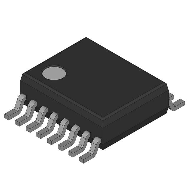
- Part No.:
- UCC5343M
- Manufacturer:
- Texas Instruments
- Category:
- Telecom
- Package:
- -
- Datasheet:
-
 UCC5343M.pdf
- Description:
- TELECOM CIRCUIT, 1-FUNC, BICMOS
- Quantity:
- Payment:

- Shipping:

Inventory:1,428
Please send an inquiry. Send us your inquiry, and we will respond immediately.
Product details
Overview
UCC5343M from Texas Instruments is an IrDA physical-layer transceiver with integrated encoder/decoder, designed for serial infrared communication between UARTs and Super I/O devices. It operates from 3V to 5V, supports up to 115.2 kbps data rates, delivers 500 mA sink current on the LED output, and achieves 200 nA minimum receiver detection threshold with 1 µA sleep current.
For engineers reviewing the UCC5343M datasheet, UCC5343M pinout, UCC5343M application, or UCC5343M equivalent, this page provides verified technical context, validated pin functions, real-world use cases in embedded IR interfaces, and confirmed alternative parts for legacy design continuity and sourcing resilience.
Technical Context
The UCC5343M implements IrDA SIR (Serial Infrared) encoding/decoding per the IrDA 1.0 Physical Layer specification. Its receiver uses a limiting transresistance amplifier with internal bandpass filtering (50 kHz–1 MHz) to reject ambient IR noise while detecting input currents from 200 nA to >50 mA.
The transmitter features an open-drain MOSFET output capable of sinking 300 mA at 3 V and 500 mA at 5 V into an IR LED. Encoder pulse width is selectable via TXMODE (1.41–2.23 µs typical), and decoding includes pulse-stretching logic to convert 3/16-bit pulses into full-bit-width RXX outputs compatible with standard UART SIN inputs.
Key Specifications
| Parameter | Value and Actual Design Meaning |
|---|---|
| Supply Voltage Range | 3 V to 5.5 V - Enables direct interface with 3.3 V and 5 V system rails without level-shifting. |
| Sleep Current | 1–3 µA - Supports ultra-low-power operation in battery-powered handheld IR peripherals. |
| Receiver Detection Threshold | 200–400 nA - Allows reliable signal capture even under weak IR link conditions or long-distance reception. |
| Max Data Rate | 115.2 kbps - Complies with IrDA SIR standard for legacy PDA, laptop, and industrial terminal communication. |
| Transmitter Sink Current | 500 mA at 5 V - Drives high-brightness IR LEDs for extended range or noisy optical environments. |
| RXX Output Pulse Width | 8.95 µs - Matches UART timing requirements for direct connection to SIN without external conditioning. |
| Bandpass Filter Range | 50 kHz to 1 MHz - Rejects fluorescent lighting, remote control carriers, and other ambient IR interference. |
Pinout & Package
UCC5343M is housed in a 16-pin SSOP package (Package Drawing: UTR), with separate analog (AGND), digital (DGND), and power-ground (PGND) pins to minimize noise coupling in mixed-signal IR systems.
| Pin/Terminal | Circuit Role | Design Meaning |
|---|---|---|
| AGND | Analog ground reference | Reference for sensitive receiver amplifier; must be isolated from digital return paths to preserve 200 nA detection capability. |
| AVDD | Analog supply rail | Powers receiver and encoder; requires local 100 nF ceramic + bulk capacitor due to high peak LED current draw. |
| CAT | PIN diode cathode filter supply | Internally connected to AGND via 20 Ω; bypassed with 4.7 µF + 100 nF to stabilize PIN bias under dynamic IR detection. |
| DET | Receiver input node | Connects directly to PIN diode anode; trace must be short and shielded by AGND to prevent leakage-induced false triggers. |
| DGND | Digital ground reference | Reference for RXX, TXX, and UART interface signals; internally tied to AVDD via 2 kΩ resistor. |
| DVDD | Digital supply rail | Derived from AVDD; powers decoder and logic; bypassed with 100 nF ceramic capacitor near pin. |
| LED | Transmitter output | Open-drain MOSFET output driving IR LED cathode; sinks up to 500 mA at 5 V for robust optical transmission. |
| PGND | Power-ground for transmitter | Carries high-current LED return path; must connect to low-impedance board ground plane to avoid voltage bounce. |
| RSTB | Active-low reset input | Resets encoder/decoder state on power-up; must be asserted by host system before enabling IrDA communication. |
| RXX | Digital receive output | TTL/CMOS-compatible demodulated output; directly connects to UART SIN; pulse-stretched for UART bit-time alignment. |
| SLEEP | Low-power mode control | Logic-high entry into 1–3 µA sleep state; reduces system power during IR idle periods without losing configuration. |
| TXMODE | Encoder pulse width select | High = 1.6 µs fixed pulse; low = 3/16-bit pulse; floating defaults to 1.6 µs - enables compatibility with multiple UART clock schemes. |
| TXX | UART transmit input | Accepts UART SOUT signal; drives internal encoder; logic thresholds defined at 0.3×DVDD / 0.7×DVDD for 5 V operation. |
| UARTCLK | System clock input | Must be exactly 16× IrDA baud rate (e.g., 1.8432 MHz for 115.2 kbps); sourced from UART or external oscillator. |
| - | Not connected (NC) | No internal connection; left unconnected per TI packaging documentation for UCC5343M (UTR package). |
Key Features
| Feature | Design Value |
|---|---|
| Integrated IrDA SIR encoder/decoder | Eliminates need for external logic or FPGA-based protocol translation; reduces BOM count and PCB area in portable IR designs. |
| Triple-ground architecture (AGND/DGND/PGND) | Enables clean separation of analog sensing, digital signaling, and high-current LED drive paths - critical for achieving 200 nA receiver sensitivity. |
| Configurable encoder pulse width | TXMODE pin allows runtime selection between 1.6 µs fixed and 3/16-bit variable pulse widths to match diverse UART clock sources and legacy host controllers. |
| Internal CAT decoupling resistors | 20 Ω internal resistor from AVDD to CAT minimizes external component count and ensures stable PIN diode bias under varying temperature and supply conditions. |
| Bandpass-filtered receiver path | 50 kHz–1 MHz internal filtering rejects 120 Hz fluorescent light harmonics and 38 kHz remote control carriers - improves link reliability in office/industrial settings. |
Applications
| Handheld Data Terminals | Industrial Barcode Scanners |
|---|---|
Use Scenario: Wireless data exchange between ruggedized handheld terminals and base stations in warehouse logistics. IC Role / Device Role / Timing Role: IrDA transceiver handling physical layer modulation/demodulation and UART-to-IrDA format translation at 115.2 kbps. Use Value: Enables cable-free firmware updates and inventory sync with <1 µA sleep current extending battery life between shifts. |
Use Scenario: Short-range optical data transfer from handheld barcode scanners to docked cradles in manufacturing QA stations. IC Role / Device Role / Timing Role: Receiver detects low-amplitude reflected IR pulses from barcodes; transmitter drives high-current LED for consistent scan illumination. Use Value: 500 mA LED sink current ensures reliable scanning under ambient light; 200 nA detection threshold captures weak returns from damaged or low-contrast codes. |
| Legacy Laptop Docking Ports | Medical Patient Monitor Interfaces |
Use Scenario: Synchronization of contactless patient data between older-generation laptops and clinical docking stations. IC Role / Device Role / Timing Role: Direct UART interface with pulse-stretched RXX output ensuring bit-aligned reception by legacy 16550-compatible UARTs. Use Value: Eliminates need for external level shifters or timing adapters; 115.2 kbps throughput meets HL7 ADT message size requirements. |
Use Scenario: Isolated parameter upload from bedside monitors to nursing station PCs in EMI-sensitive ICU environments. IC Role / Device Role / Timing Role: Transceiver provides galvanically isolated communication channel using IR instead of USB or RS-232. Use Value: Bandpass filtering suppresses EMI from adjacent infusion pumps and ventilators; triple-ground layout prevents noise coupling into analog sensor circuits. |
Equivalent & Alternatives
The following parts are listed as comparable options for similar IrDA transceiver applications.
| Alternative Part | Technical Difference | Application Difference | Selection Advice |
|---|---|---|---|
| Vishay TFBS4650 | Integrated photodiode + LED driver; no UART interface or encoder/decoder logic; requires external microcontroller for protocol handling. | Used in simpler point-to-point IR links where host handles IrDA stack; lacks RXX/TXX direct UART compatibility. | Select when minimizing component count outweighs need for full IrDA PHY integration and UART bridging. |
| MAX3221E | RS-232 transceiver only; no IR functionality, no encoder/decoder, no LED drive capability; operates at ±15 V supply. | Designed for wired serial communication; incompatible with IrDA optical physical layer or low-voltage battery operation. | Not functionally equivalent; consider only if migrating from wired to wireless requires complete redesign with separate IR PHY and UART controller. |
Compared with UCC5343M, TFBS4650 offers lower system-level integration but higher optical efficiency in dedicated IR link designs, while MAX3221E serves a fundamentally different wired interface role and cannot substitute for IrDA functionality without architectural rework.
Availability
UCC5343M is available at Aetrix Electronics and suitable for legacy industrial terminal upgrades, medical device maintenance programs, and embedded IR communication modules requiring stable component supply despite end-of-life status.
Supply support for UCC5343M includes scheduled delivery planning, volume procurement assistance, BOM continuity management, traceable sourcing, and lifecycle availability coordination for OEM customers, industrial embedded developers, connected-device designers, and electronics production programs.
Manufacturer
Texas Instruments is a global semiconductor leader headquartered in Dallas, Texas, delivering analog, embedded processing, and connectivity solutions across industrial, automotive, and communications markets.
The UCC5343M belongs to TI's legacy IrDA transceiver product line, engineered specifically for low-power, UART-integrated infrared communication in portable and embedded systems compliant with IrDA 1.0 SIR specifications.
FAQ
What is the primary function of the UCC5343M in an IrDA communication system?
The UCC5343M serves as a complete IrDA physical-layer transceiver with integrated encoder and decoder logic. It converts UART-level signals into IrDA-compliant modulated infrared pulses for transmission and demodulates received IR signals back into UART-compatible digital outputs. Its direct UART interface, 115.2 kbps support, and 200 nA detection threshold make it suitable for battery-powered handheld devices requiring robust short-range optical data transfer without external protocol handling.
Does the UCC5343M require external components to operate with a standard UART?
Yes, the UCC5343M requires several external passive components for proper operation: a 100 nF ceramic capacitor between AVDD and AGND, a 100 nF capacitor between DVDD and DGND, a 4.7 µF electrolytic + 100 nF ceramic capacitor between CAT and AGND, and appropriate IR LED and PIN diode circuitry. These components ensure stable power delivery, noise suppression, and optimal optical coupling - all specified in the official TI application notes for UCC5343M.
What does the SLEEP pin do on the UCC5343M, and how is it controlled?
The SLEEP pin on the UCC5343M controls ultra-low-power mode: applying a logic high (≥ AVDD – 0.5 V) reduces supply current to 1–3 µA, ideal for standby operation in portable IR devices. A logic low (≤ 0.5 V) disables sleep mode and enables full transceiver functionality. This pin is not auto-managed - it must be driven by the host system's GPIO or power-management controller based on communication activity.
Can the UCC5343M support IrDA data rates higher than 115.2 kbps?
No, the UCC5343M is specified only for IrDA SIR (Serial Infrared) operation up to 115.2 kbps, as confirmed by its electrical characteristics table, timing diagrams, and application notes. It does not support MIR (1.152 Mbps) or FIR (4 Mbps) modes. Attempting higher rates will result in failed encoding/decoding due to fixed internal clock division and pulse-width constraints defined in the UCC5343M datasheet.
Is the UCC5343M still in active production, and what are the implications for new designs?
No, the UCC5343M is marked OBSOLETE by Texas Instruments per its official packaging addendum. While Aetrix Electronics maintains limited legacy stock and supports continuity programs, TI no longer manufactures or warrants new shipments. For new designs, engineers should evaluate modern alternatives such as the Vishay TFBS4652 or implement software-defined IR using microcontrollers with timer-based PWM and ADC-based detection - but full functional replacement of UCC5343M requires careful validation of timing, noise immunity, and UART integration.
UCC5343M Specifications
- Product attributes
- Attribute value
- Manufacturer:
- Texas Instruments
- Series:
- *
- Package/Case:
- -
- Packaging:
- Bulk
- Product Status:
- Active
- Function:
- -
- Interface:
- -
- Number of Circuits:
- -
- Voltage - Supply:
- -
- Current - Supply:
- -
- Power (Watts):
- -
- Operating Temperature:
- -
- Grade:
- -
- Qualification:
- -
- Mounting Type:
- -
- Supplier Device Package:
- -
UCC5343M FAQ
1.How can I place an order for UCC5343M through Aetrix?
Please submit a Request for Quotation (RFQ) for UCC5343M on Aetrix. Our sales agent will provide a competitive quotation and guide you through the order confirmation once you accept the terms.
2.Are the price and stock information for UCC5343M reliable?
The price and inventory of UCC5343M are updated periodically and may fluctuate due to market conditions. Stock and pricing data are typically refreshed every 24 hours. Quotation validity for UCC5343M is usually 5 days.
3.What payment methods are accepted for UCC5343M?
We accept Wire Transfer, PayPal, Credit Card, Western Union, MoneyGram, and Escrow for UCC5343M transactions.
Note: Certain payment methods may incur a processing fee.
4.How is shipping managed for UCC5343M?
UCC5343M orders can be shipped via leading logistics carriers, including DHL, UPS, FedEx, TNT, or Registered Mail.
Once your UCC5343M order is processed, you will receive an email with the shipment details and tracking number.
Note: Tracking information may take up to 24 hours to appear. Express delivery typically takes 3–5 business days.
5.How can I obtain technical support or documentation for UCC5343M?
For technical support, including UCC5343M datasheets, pinout diagrams, or application guidance, please contact our engineering support team. They can provide detailed documentation and assistance for your UCC5343M requirements.
6.How does Aetrix verify that UCC5343M is sourced from the original manufacturer or authorized distributors?
All UCC5343M products on Aetrix are procured from qualified distributors and authorized channels. Our dedicated quality assurance team conducts strict verification, including traceability checks and, if necessary, third-party testing. This ensures that UCC5343M meets industry standards.
7.What is the process for return or replacement of UCC5343M?
All UCC5343M units undergo pre-shipment inspection (PSI). If there is an issue with UCC5343M, returns or replacements are accepted under the following conditions:
1.Quantity discrepancies, incorrect items, or visible external defects (such as breakage or corrosion), acknowledged by Aetrix.
2.The issue is reported within 90 days of delivery.
3.The UCC5343M part is unused and in its original packaging.
Return procedure for UCC5343M:
1.Submit a request within 90 days.
2.Obtain a Return Material Authorization (RMA) from Aetrix.
UCC5343M Tags

-
LMC567CMX/NOPB
Texas Instruments
-
LM567CMX/NOPB
Texas Instruments
-
LM567CM/NOPB
Texas Instruments

-
VSC8531XMW-02
Microchip Technology
-
VSC8531XMW-05
Microchip Technology

-
GPY115C0VI
MaxLinear, Inc.

-
SI32185-A-FMR
Skyworks Solutions Inc.

-
VSC8541XMV-05
Microchip Technology

-
SI32178-B-FM1R
Skyworks Solutions Inc.
-
GPY215C0VI
MaxLinear, Inc.

-
CPC7514ZTR
Littelfuse Inc.

-
VSC8502XML-03
Microchip Technology
Tech Hub

A practical engineering guide to 3.3V and 5V logic compatibility, input thresholds, resistor dividers, translator ICs, MOSFET level shifting, I2C pull-ups, timing limits and power-sequencing risks.

The 74HC595 uses push-pull logic outputs, while the TPIC6B595 uses 50 V open-drain DMOS sinks for higher-power loads. This guide compares timing, current limits, 3.3 V interfacing, load wiring, thermal…

The 74HC595 converts serial data into eight stable parallel outputs. This guide covers pin functions, shift and storage timing, OE and MR behavior, drive-current limits, cascading, voltage compatibilit…

A technical comparison of level-sensitive latches and edge-triggered flip-flops, covering timing windows, setup and hold limits, master–slave operation, time borrowing, race-through, HDL inference and…

A D latch stores one bit while Enable controls when data can pass. This reference covers gate-level operation, truth tables, transparency, setup and hold timing, LE versus OE, common ICs and practical …

An SR latch stores one bit through cross-coupled feedback. This engineering reference covers NOR and NAND implementations, truth tables, forbidden-state recovery, gated operation, switch debouncing, fa…

Latch circuits retain one bit through feedback. This technical reference covers SR and D latches, truth tables, transparency, timing limits, latch-versus-flip-flop behavior, applications and common log…

An engineering guide to LED driver operation, constant-current and constant-voltage outputs, linear and switching topologies, dimming, IC selection, calculations, replacement compatibility, and fault c…

Operational amplifier guide covering op amp basics, feedback, ideal vs real op amps, common configurations, buffer circuits, offset, bias current, gain-bandwidth, slew rate, rail-to-rail limits and sel…

Jumper cables guide covering safe connection order, red and black clamp placement, final ground connection, cable gauge, length, clamp quality, copper vs CCA cables, jump starter comparison and battery…


