
 My Inquiry
 My Account


NXP Semiconductors UJA1076TW/5V0/WD,1
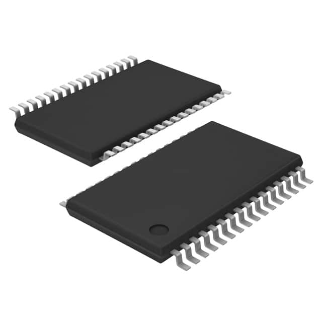
- Part No.:
- UJA1076TW/5V0/WD,1
- Manufacturer:
- NXP Semiconductors
- Category:
- Specialized
- Package:
- 32-TSSOP (0.240", 6.10mm Width) Exposed Pad
- Datasheet:
-
 UJA1076TW/5V0/WD,1.pdf
- Description:
- IC INTFACE SPECIALIZED 32HTSSOP
- Quantity:
- Payment:

- Shipping:

Inventory:2,556
Please send an inquiry. Send us your inquiry, and we will respond immediately.
Product details
Overview
UJA1076TW/5V0/WD from NXP Semiconductors is a high-speed CAN core System Basis Chip (SBC) integrating a CAN transceiver compliant with ISO 11898-2/5, a 5 V ±2 % voltage regulator delivering up to 250 mA for microcontrollers, an independent 5 V CAN transceiver supply (V2), a programmable window/timeout watchdog, and full-duplex SPI interface - deployed in automotive Electronic Control Units for controlled power-up, diagnostics, and limp-home safety response.
For engineers reviewing the UJA1076TW/5V0/WD datasheet, UJA1076TW/5V0/WD pinout, UJA1076TW/5V0/WD application, or UJA1076TW/5V0/WD equivalent, key selection criteria include its HTSSOP32 package with exposed die pad, dual-regulator architecture enabling cranking operation down to 4.5 V (V1) and 5.5 V (V2), wake-up source detection on WAKE1/WAKE2, and SPI-configurable system modes (Standby/Normal/Sleep) with overtemperature shutdown and LIMP output activation.
Technical Context
The UJA1076TW/5V0/WD implements a state-machine-based system controller managing five operating modes (Off, Standby, Normal, Sleep, Overtemp) with deterministic transitions triggered by battery voltage thresholds, wake events, or register writes. Its CAN transceiver features SPLIT pin stabilization, floating bus pins in Off mode, and ±58 V short-circuit protection on CANH/CANL.
Power management includes two independent regulators: V1 (5 V, 250 mA, ±2 % accuracy, extendable via external PNP transistor) and V2 (5 V dedicated for CAN transceiver), both supporting undervoltage warning (90 % threshold) and configurable reset thresholds (90 % or 70 %). The on-chip oscillator drives the watchdog independently of V1/V2 supplies.
Key Specifications
| Parameter | Value and Actual Design Meaning |
|---|---|
| CAN Standard | ISO 11898-2 and ISO 11898-5 compliant high-speed transceiver; interoperable with TJA1042 |
| Main Regulator (V1) | 5 V ±2 % output; delivers up to 250 mA; supports cranking down to 4.5 V; extendable with external PNP transistor |
| CAN Regulator (V2) | 5 V dedicated output for internal transceiver; undervoltage warning at 90 %; switchable off |
| Watchdog | Programmable window/timeout/off modes; default period 128 ms; clocked by on-chip oscillator |
| SPI Interface | Full-duplex 16-bit interface; supports read-only register access; SCSN active-low, SCK idle-low |
| Package | HTSSOP32 (SOT549-1); 6.1 mm × 11 mm; 0.65 mm pitch; exposed die pad for thermal dissipation |
| ESD Protection | ±8 kV HBM and ±6 kV IEC 61000-4-2 on CANH/CANL and WAKE1/WAKE2 pins |
| Operating Voltage Range | VBAT = 4.5 V to 27 V; V1 functional down to 4.5 V (ISO 7637-4b), V2 down to 5.5 V (ISO 7637-4) |
Pinout & Package
Package: HTSSOP32 (SOT549-1), thermally enhanced plastic thin shrink small outline package with 32 leads, 6.1 mm body width, 0.65 mm lead pitch, and exposed die pad (electrically isolated, may be left floating or connected to GND).
| Pin/Terminal | Circuit Role | Design Meaning |
|---|---|---|
| BAT (32) | Battery input | Main supply input (4.5 V–27 V); powers internal regulators and logic; protected per ISO 7637-3 |
| V1 (4) | Main regulator output | 5 V ±2 % supply for microcontroller and peripherals; supports external PNP extension |
| V2 (20) | CAN transceiver regulator | Dedicated 5 V supply for internal CAN transceiver; improves EMC and isolates CAN from MCU rail |
| RSTN (6) | Bidirectional reset | Active-low reset I/O; variable power-on reset length; driven LOW during Overtemp or Sleep mode |
| INTN (7) | Interrupt output | Open-drain interrupt signal; individually configurable for V1/V2 undervoltage, wake-up, cyclic, or power-on events |
| WAKE1 (18), WAKE2 (19) | Local wake inputs | Configurable wake sources with selectable 16 ms/64 ms sampling; support wake bias control via WBIAS (28) |
| LIMP (17) | Limp-home output | Active-low output activated during Overtemp or software-triggered limp-home condition; drives external fail-safe hardware |
| SDI/SDO/SCK/SCSN (9–12) | SPI interface | Full-duplex serial interface for configuration, status reporting, and diagnostics; supports multi-slave operation |
| CANH/CANL (21–22) | CAN bus interface | Differential high-speed CAN physical layer; ±58 V short-circuit proof; SPLIT (24) stabilizes recessive bus level |
| WDOFF (16) | Watchdog disable | Hardware watchdog deactivation pin; HIGH disables watchdog regardless of register settings |
Key Features
| Feature | Design Value |
|---|---|
| Integrated CAN ECU functions | Combines CAN transceiver, dual regulators (V1/V2), watchdog, SPI, wake inputs, and LIMP output in one HTSSOP32 IC - eliminates discrete BOM components and reduces PCB area |
| Automotive-grade robustness | ±8 kV HBM / ±6 kV IEC 61000-4-2 ESD on CAN/wake pins; ±58 V short-circuit proof CANH/CANL; ISO 7637-3 transient protection on BAT/CAN |
| Intelligent power sequencing | Controlled start-up behavior with safe mode transitions; V1 remains active in Standby to maintain MCU supply while CAN transceiver enters Lowpower/Off mode |
| Diagnostic & safety architecture | Detailed status reporting via SPI registers (WD_and_Status, Int_Status); overtemperature shutdown with automatic LIMP activation; configurable undervoltage interrupts |
| Flexible wake-up management | Two local wake inputs with bias control (WBIAS), CAN bus wake detection, and cyclic wake capability - enables ultra-low-current Standby/Sleep modes with full wake responsiveness |
Applications
| Body Control Module (BCM) | Engine Control Unit (ECU) |
|---|---|
|
Use Scenario: Centralized power and communication management for door locks, lighting, and climate controls in modern vehicles. IC Role / Device Role / Timing Role: UJA1076TW/5V0/WD acts as the primary SBC, supplying regulated 5 V to the BCM microcontroller, enabling CAN bus communication, and providing wake-up detection from door switches or key fobs. Use Value: Enables reliable low-power Standby mode with <100 µA current draw while maintaining full wake responsiveness via WAKE1/WAKE2 and CAN bus activity - critical for battery-sensitive applications. |
Use Scenario: Power and interface management for engine management systems requiring high reliability under cranking and load dump conditions. IC Role / Device Role / Timing Role: UJA1076TW/5V0/WD provides stable 5 V V1 supply down to 4.5 V during cranking, powers the CAN transceiver via isolated V2 rail, and triggers LIMP output upon overtemperature or critical fault. Use Value: Ensures continuous operation during ISO 16750-2 cranking pulses and ISO 7637-2 load dumps, while LIMP output activates mechanical fail-safes (e.g., throttle limiter) without MCU intervention. |
| Transmission Control Unit (TCU) | Advanced Driver Assistance Systems (ADAS) ECU |
|
Use Scenario: Robust power and CAN interface for gear-shifting logic and torque management in automatic transmissions. IC Role / Device Role / Timing Role: UJA1076TW/5V0/WD supplies regulated 5 V to TCU MCU, manages CANH/CANL bus integrity with SPLIT pin stabilization, and monitors V1/V2 undervoltage with SPI-reportable status. Use Value: Prevents transmission mis-shifts during voltage sags by generating precise undervoltage interrupts (90 % threshold) and initiating controlled resets before logic corruption occurs. |
Use Scenario: Safety-critical subsystem powering radar or camera processing units requiring fail-operational behavior. IC Role / Device Role / Timing Role: UJA1076TW/5V0/WD serves as the foundational SBC, delivering isolated V1 (MCU) and V2 (CAN) rails, executing watchdog supervision, and asserting LIMP to trigger redundant sensor shutdown or fallback mode. Use Value: Meets ASIL-B functional safety requirements through deterministic overtemperature shutdown, hardware watchdog with window mode, and SPI-accessible diagnostic registers for runtime health monitoring. |
Equivalent & Alternatives
The following parts are listed as comparable options for similar System Basis Chip applications.
| Alternative Part | Technical Difference | Application Difference | Selection Advice |
|---|---|---|---|
| TJA1042TK/3 | Standalone high-speed CAN transceiver only; no regulators, watchdog, or SPI; ISO 11898-2/5 compliant; 5 V supply required externally | Requires external 5 V regulator, microcontroller reset circuitry, and wake-up logic - increases BOM count and design complexity | Select when only CAN physical layer is needed and system-level power management is handled elsewhere |
| UJA1075TW/5V0/WD | Pin-compatible predecessor; lacks V2 regulator - CAN transceiver powered from V1; no separate V2 rail or V2 undervoltage monitoring | Reduced EMC performance due to shared V1/V2 supply; no independent CAN rail monitoring or V2 shutdown capability | Select only for legacy designs where V2 isolation and dedicated CAN supply are not required |
Compared with TJA1042TK/3 and UJA1075TW/5V0/WD, the UJA1076TW/5V0/WD delivers integrated dual-regulator architecture with isolated V2, enabling superior EMC, independent fault monitoring, and simplified layout - making it optimal for new automotive ECU designs demanding compact, robust, and diagnostics-rich SBC functionality.
Availability
UJA1076TW/5V0/WD is available at Aetrix Electronics and suitable for automotive Body Control Modules, Engine Control Units, Transmission Control Units, and ADAS ECUs requiring stable component supply, long-term lifecycle support, and AEC-Q100 qualified reliability.
Supply support for UJA1076TW/5V0/WD includes scheduled delivery planning, volume procurement assistance, BOM continuity management, traceable sourcing, and lifecycle availability coordination for OEM customers, industrial embedded developers, connected-device designers, and electronics production programs.
Manufacturer
NXP Semiconductors is a global semiconductor leader specializing in secure connectivity solutions for automotive, industrial, and IoT applications, with deep expertise in CAN, SBC, and automotive power management ICs.
The UJA1076TW/5V0/WD belongs to NXP's System Basis Chip product line, designed specifically for automotive Electronic Control Units to consolidate discrete power, interface, and safety functions into a single AEC-Q100 qualified device with advanced diagnostics and low-power operation.
FAQ
What is the primary function of the UJA1076TW/5V0/WD in an automotive ECU?
The UJA1076TW/5V0/WD serves as a core System Basis Chip that integrates a high-speed CAN transceiver, dual voltage regulators (5 V V1 for MCU and 5 V V2 for CAN), a programmable watchdog, SPI interface, wake-up inputs, and limp-home output. It replaces multiple discrete components in automotive ECUs to ensure controlled power-up, robust communication, fault diagnostics, and fail-safe response - all within a single HTSSOP32 package.
Does the UJA1076TW/5V0/WD support operation during automotive cranking conditions?
Yes, the UJA1076TW/5V0/WD supports cranking operation: its V1 regulator remains functional down to 4.5 V (per ISO 7637-4b and ISO 16750-2), and V2 operates down to 5.5 V (per ISO 7637-4). This ensures uninterrupted microcontroller supply and CAN communication during engine start-up voltage sags, a critical requirement for Body Control Modules and Engine Control Units.
How does the watchdog in the UJA1076TW/5V0/WD differ between Window and Timeout modes?
In Window mode, the UJA1076TW/5V0/WD requires watchdog triggers within a defined time window (first half of period) to avoid reset; triggering too early or missing the window causes immediate reset. In Timeout mode, any trigger resets the timer, and overflow sets a cyclic interrupt - only overflow with pending interrupt causes reset. Both modes use the same on-chip oscillator and support programmable periods from 8 ms to 4096 ms.
Can the UJA1076TW/5V0/WD supply external components beyond the microcontroller?
Yes, the UJA1076TW/5V0/WD's V1 regulator delivers up to 250 mA at 5 V ±2 % and is explicitly designed to power not only the microcontroller but also its peripherals and additional external transceivers. An external PNP transistor can be added via VEXCTRL/VEXCC pins to increase current capability and distribute heat across the PCB - confirmed in Section 2.1 and Figure 7 of the datasheet.
What safety mechanisms does the UJA1076TW/5V0/WD provide for automotive fail-operational systems?
The UJA1076TW/5V0/WD provides overtemperature shutdown with automatic LIMP output activation, configurable undervoltage interrupts on V1/V2, hardware watchdog with window mode, bidirectional RSTN with variable reset timing, and SPI-accessible status registers for real-time diagnostics. These features enable fail-operational behavior in systems like ADAS ECUs, where the UJA1076TW/5V0/WD can assert LIMP to activate mechanical fallbacks independently of MCU software state.
UJA1076TW/5V0/WD,1 Specifications
- Product attributes
- Attribute value
- Manufacturer:
- NXP Semiconductors
- Series:
- -
- Package/Case:
- 32-TSSOP (0.240", 6.10mm Width) Exposed Pad
- Packaging:
- Tape & Reel (TR)
- Product Status:
- Obsolete
- Applications:
- -
- Interface:
- SPI Serial
- Voltage - Supply:
- 4.5V ~ 28V
- Supplier Device Package:
- 32-HTSSOP
- Grade:
- Automotive
- Qualification:
- -
- Mounting Type:
- Surface Mount
UJA1076TW/5V0/WD,1 FAQ
1.How can I place an order for UJA1076TW/5V0/WD,1 through Aetrix?
Please submit a Request for Quotation (RFQ) for UJA1076TW/5V0/WD,1 on Aetrix. Our sales agent will provide a competitive quotation and guide you through the order confirmation once you accept the terms.
2.Are the price and stock information for UJA1076TW/5V0/WD,1 reliable?
The price and inventory of UJA1076TW/5V0/WD,1 are updated periodically and may fluctuate due to market conditions. Stock and pricing data are typically refreshed every 24 hours. Quotation validity for UJA1076TW/5V0/WD,1 is usually 5 days.
3.What payment methods are accepted for UJA1076TW/5V0/WD,1?
We accept Wire Transfer, PayPal, Credit Card, Western Union, MoneyGram, and Escrow for UJA1076TW/5V0/WD,1 transactions.
Note: Certain payment methods may incur a processing fee.
4.How is shipping managed for UJA1076TW/5V0/WD,1?
UJA1076TW/5V0/WD,1 orders can be shipped via leading logistics carriers, including DHL, UPS, FedEx, TNT, or Registered Mail.
Once your UJA1076TW/5V0/WD,1 order is processed, you will receive an email with the shipment details and tracking number.
Note: Tracking information may take up to 24 hours to appear. Express delivery typically takes 3–5 business days.
5.How can I obtain technical support or documentation for UJA1076TW/5V0/WD,1?
For technical support, including UJA1076TW/5V0/WD,1 datasheets, pinout diagrams, or application guidance, please contact our engineering support team. They can provide detailed documentation and assistance for your UJA1076TW/5V0/WD,1 requirements.
6.How does Aetrix verify that UJA1076TW/5V0/WD,1 is sourced from the original manufacturer or authorized distributors?
All UJA1076TW/5V0/WD,1 products on Aetrix are procured from qualified distributors and authorized channels. Our dedicated quality assurance team conducts strict verification, including traceability checks and, if necessary, third-party testing. This ensures that UJA1076TW/5V0/WD,1 meets industry standards.
7.What is the process for return or replacement of UJA1076TW/5V0/WD,1?
All UJA1076TW/5V0/WD,1 units undergo pre-shipment inspection (PSI). If there is an issue with UJA1076TW/5V0/WD,1, returns or replacements are accepted under the following conditions:
1.Quantity discrepancies, incorrect items, or visible external defects (such as breakage or corrosion), acknowledged by Aetrix.
2.The issue is reported within 90 days of delivery.
3.The UJA1076TW/5V0/WD,1 part is unused and in its original packaging.
Return procedure for UJA1076TW/5V0/WD,1:
1.Submit a request within 90 days.
2.Obtain a Return Material Authorization (RMA) from Aetrix.
UJA1076TW/5V0/WD,1 Tags

-
NVT4857UKAZ
NXP Semiconductors

-
TCA8418RTWR
Texas Instruments

-
PCA9546APWR
Texas Instruments

-
MD0100N8-G
Microchip Technology

-
PCA9548APW,118
NXP Semiconductors

-
PCA9540BDP,118
NXP Semiconductors

-
PCA9548APWR
Texas Instruments

-
PCA9546APW,118
NXP Semiconductors

-
PTN3360DBS,518
NXP Semiconductors

-
PCA9546ABS,118
NXP Semiconductors

-
PCA9518PWR
Texas Instruments

-
PCA9545APW,118
NXP Semiconductors
Tech Hub

A practical engineering guide to 3.3V and 5V logic compatibility, input thresholds, resistor dividers, translator ICs, MOSFET level shifting, I2C pull-ups, timing limits and power-sequencing risks.

The 74HC595 uses push-pull logic outputs, while the TPIC6B595 uses 50 V open-drain DMOS sinks for higher-power loads. This guide compares timing, current limits, 3.3 V interfacing, load wiring, thermal…

The 74HC595 converts serial data into eight stable parallel outputs. This guide covers pin functions, shift and storage timing, OE and MR behavior, drive-current limits, cascading, voltage compatibilit…

A technical comparison of level-sensitive latches and edge-triggered flip-flops, covering timing windows, setup and hold limits, master–slave operation, time borrowing, race-through, HDL inference and…

A D latch stores one bit while Enable controls when data can pass. This reference covers gate-level operation, truth tables, transparency, setup and hold timing, LE versus OE, common ICs and practical …

An SR latch stores one bit through cross-coupled feedback. This engineering reference covers NOR and NAND implementations, truth tables, forbidden-state recovery, gated operation, switch debouncing, fa…

Latch circuits retain one bit through feedback. This technical reference covers SR and D latches, truth tables, transparency, timing limits, latch-versus-flip-flop behavior, applications and common log…

An engineering guide to LED driver operation, constant-current and constant-voltage outputs, linear and switching topologies, dimming, IC selection, calculations, replacement compatibility, and fault c…

Operational amplifier guide covering op amp basics, feedback, ideal vs real op amps, common configurations, buffer circuits, offset, bias current, gain-bandwidth, slew rate, rail-to-rail limits and sel…

Jumper cables guide covering safe connection order, red and black clamp placement, final ground connection, cable gauge, length, clamp quality, copper vs CCA cables, jump starter comparison and battery…


