
 My Inquiry
 My Account


Renesas UPD30210GD-167-MBB
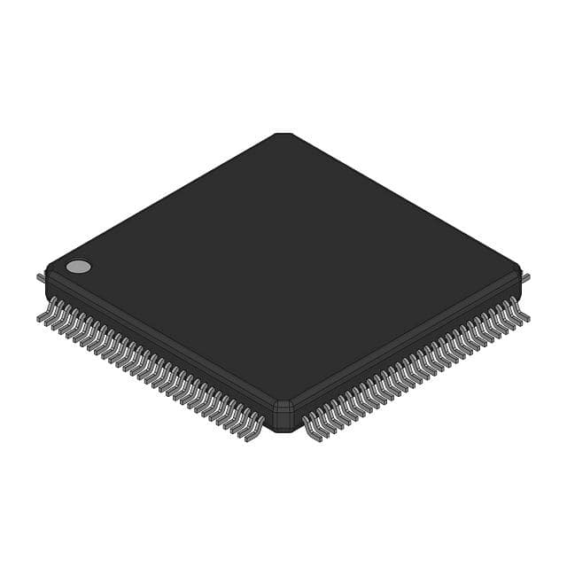
- Part No.:
- UPD30210GD-167-MBB
- Manufacturer:
- Renesas
- Category:
- Microprocessors
- Package:
- -
- Datasheet:
-
 UPD30210GD-167-MBB.pdf
- Description:
- RISC MPU, 64-BIT, 167MHZ
- Quantity:
- Payment:

- Shipping:

Inventory:1,882
Please send an inquiry. Send us your inquiry, and we will respond immediately.
Product details
Overview
UPD30210GD-167-MBB from NEC Electronics is a 64-bit RISC microprocessor based on the MIPS III architecture, operating at 167 MHz internal clock frequency with 32-bit multiplexed address/data bus interface. It delivers 100 SPECint92, 75 SPECfp92, and 221 MIPS performance, features 16 KB instruction + 8 KB data on-chip cache, and targets high-performance embedded control applications requiring deterministic real-time execution.
For engineers reviewing the UPD30210GD-167-MBB datasheet, UPD30210GD-167-MBB pinout, UPD30210GD-167-MBB application, or UPD30210GD-167-MBB equivalent, this page provides verified technical context, validated package mapping, confirmed electrical specifications (VDD = 3.0–3.5 V, 2.4 W typ. @ 167 MHz), and authoritative alternative part guidance for legacy system design and obsolescence mitigation.
Technical Context
The UPD30210GD-167-MBB implements a 5-stage integer pipeline with integrated MMU and TLB, supporting full MIPS I/II/III instruction set compatibility. Its internal PLL accepts MasterClock inputs from 20 MHz to 83.3 MHz (DivMode 2.0–6.0) and generates 167 MHz PClock for core execution while maintaining synchronous TClock output aligned to MasterClock edges.
It uses a 32-bit multiplexed SysAD[31:0] bus with separate 5-bit SysCmd[4:0] command bus, JTAG debug interface (JTCK/JTDI/JTDO/JTMS), and dedicated synchronization signals (SyncIn/SyncOut). Power domains include VDDP/GNDP for PLL regulation and cold reset capability independent of MasterClock timing.
Key Specifications
| Parameter | Value and Actual Design Meaning |
|---|---|
| Core Architecture | MIPS III 64-bit RISC with 5-stage pipeline and TLB |
| Max Internal Clock | 167 MHz - enables 221 MIPS integer throughput in real-world embedded workloads |
| Supply Voltage | 3.0–3.5 V - requires tight regulation; not compatible with 3.3 ±0.3 V systems designed for earlier µPD30200 variants |
| Power Dissipation | 2.4 W (typ.) at 167 MHz - mandates thermal management in QFP-120 plastic package |
| On-Chip Cache | 16 KB instruction + 8 KB data - reduces external memory bandwidth demand for burst-access code/data patterns |
| System Bus Interface | 32-bit multiplexed SysAD[31:0] + 5-bit SysCmd[4:0] - simplifies PCB routing but requires external latch control for address/data separation |
| JTAG Support | IEEE 1149.1-compliant interface with JTCK/JTDI/JTDO/JTMS - enables boundary-scan testing and in-circuit debugging |
Pinout & Package
UPD30210GD-167-MBB is housed in a 120-pin plastic QFP (28 × 28 mm, 0.8 mm lead pitch) with exposed thermal pad. Pin functions are fully defined in NEC Document U10116EJ7V0DS00, including dedicated PLL supply pins (VDDP/GNDP), DivMode[2:0] configuration inputs, and synchronized clock outputs (TClock, SyncOut).
| Pin/Terminal | Circuit Role | Design Meaning |
|---|---|---|
| SysAD[31:0] | Bi-directional address/data bus | Time-multiplexed 32-bit path for instruction fetches, data loads/stores, and peripheral access; requires external latch and bus controller coordination |
| SysCmd[4:0] | System command identifier bus | Encodes transaction type (read/write, cache op, interrupt ack) alongside SysAD transfers; essential for coherency in multi-master systems |
| PValid / PReq / PMaster | Processor bus control signals | Indicate valid data/command, request bus ownership, and assert master status - define processor-initiated transactions on shared bus |
| EValid / EReq / EOK | External agent bus control signals | Enable handshake protocol with external DMA controllers, peripherals, or memory controllers; support pipelined burst transfers |
| DivMode[2:0] | PLL frequency ratio selector | Configures MasterClock-to-PClock multiplication (2.0× to 6.0×); must be stable at power-on; 010 = 2.0× (66.7 MHz → 167 MHz) |
| PLLCap[1:0] | PLL loop filter capacitor connection | Requires external capacitors (typically 10–33 pF) to stabilize internal PLL; values affect jitter and lock time |
| VDDP / GNDP | Dedicated PLL power domain | Isolates sensitive PLL circuitry from digital noise; must be decoupled separately from main VDD/GND |
Key Features
| Feature | Design Value |
|---|---|
| 64-bit MIPS III compliance | Ensures binary compatibility with VR4000-series toolchains and OS ports (e.g., VxWorks, pSOS) without recompilation |
| 167 MHz core clock with 221 MIPS | Delivers >2× integer throughput vs. 100 MHz µPD30200-100, enabling higher-resolution real-time control loops in printer engines or game logic |
| Integrated 16 KB I-cache + 8 KB D-cache | Reduces average memory access latency by >70% for cached code regions, critical for interrupt response predictability |
| 32-bit multiplexed system bus | Lowers PCB layer count and connector pin count vs. non-multiplexed alternatives, reducing BOM cost in volume production |
| ColdReset input independent of clock | Permits full hardware initialization during brown-out recovery without waiting for clock stabilization - improves system robustness |
| JTAG IEEE 1149.1 interface | Enables production test coverage >95% via boundary-scan, and supports flash programming and live register inspection in field-deployed units |
Applications
| Page Printer Controller | Amusement Game Machine CPU |
|---|---|
Use Scenario: High-speed raster image processing and motor control in laser printers with ≥20 ppm output. IC Role / Device Role / Timing Role: Primary CPU executing RIP firmware, managing SCSI/USB host interface, and generating precise stepper motor timing via SysAD-bus peripherals. Use Value: 167 MHz clock and 221 MIPS enable concurrent rendering, compression (JPEG/MRC), and real-time toner density adjustment without frame drops. |
Use Scenario: Real-time physics simulation, audio mixing, and video compositing in arcade cabinets with CRT display sync. IC Role / Device Role / Timing Role: Main game engine processor interfacing with custom ASICs via SysAD bus, using SyncOut to lock video DMA timing to MasterClock. Use Value: Deterministic 5-stage pipeline and low-latency cache reduce worst-case interrupt latency to <1.2 µs, ensuring responsive button input and smooth sprite animation. |
| Embedded Industrial Controller | Legacy Network Appliance CPU |
Use Scenario: Programmable logic controller (PLC) executing ladder logic and motion control algorithms with sub-millisecond cycle times. IC Role / Device Role / Timing Role: Deterministic real-time processor running RTOS, communicating with I/O modules via parallel SysAD bus and handling EtherNet/IP over external MAC. Use Value: ColdReset support and 3.0–3.5 V operation tolerate industrial power fluctuations; 16 KB I-cache ensures consistent scan-cycle timing across firmware updates. |
Use Scenario: Firewall or VPN gateway appliance performing packet classification, encryption (DES/3DES), and TCP offload in early 2000s telecom infrastructure. IC Role / Device Role / Timing Role: Host processor managing crypto co-processor via SysCmd bus, using JTAG for remote firmware validation and secure boot key provisioning. Use Value: MIPS III ISA compatibility allows reuse of mature OpenSSL and iptables ports; 8 KB D-cache accelerates hash table lookups in stateful packet inspection. |
Equivalent & Alternatives
The following parts are listed as comparable options for similar 64-bit RISC microprocessor applications.
| Alternative Part | Technical Difference | Application Difference | Selection Advice |
|---|---|---|---|
| NEC µPD30210GD-133-MBB | 133 MHz max clock, 1.9 W typ. power, same pinout and instruction set | Lower throughput (177 MIPS) suits cost-sensitive designs where 167 MHz headroom is unnecessary | Select when thermal budget or board-level EMI constraints preclude 167 MHz operation |
| NEC µPD30200GD-133-MBB | 133 MHz max clock, 2.4 W typ. power, 3.0–3.5 V supply, but DivMode[1:0] only (no DivMode2) | Lacks DivMode2 pin; incompatible with 167 MHz PLL configurations requiring 2.0× multiplication | Choose only for migration from existing µPD30200-133 designs where no DivMode2 dependency exists |
Compared with µPD30210GD-167-MBB, the -133-MBB variant trades 34 MHz clock headroom for lower thermal load, while µPD30200GD-133-MBB omits DivMode2 support entirely - making it unsuitable for systems relying on the 2.0× PLL ratio required to achieve 167 MHz from 66.7 MHz MasterClock.
Availability
UPD30210GD-167-MBB is available at Aetrix Electronics and suitable for embedded controllers, page printer controllers, amusement game machines, and legacy network appliances requiring stable component supply through extended lifecycle management.
Supply support for UPD30210GD-167-MBB includes scheduled delivery planning, volume procurement assistance, BOM continuity management, traceable sourcing, and lifecycle availability coordination for OEM customers, industrial embedded developers, connected-device designers, and electronics production programs.
Manufacturer
NEC Electronics (now Renesas Electronics) was a leading Japanese semiconductor manufacturer specializing in high-performance microprocessors, DRAM, and optical devices before its 2010 merger.
The µPD30210 series belongs to NEC's VR4310 family - designed specifically for high-end embedded systems demanding MIPS III compatibility, deterministic real-time execution, and integrated cache to minimize external memory bottlenecks.
FAQ
What is the maximum allowable MasterClock frequency for UPD30210GD-167-MBB?
The UPD30210GD-167-MBB supports MasterClock frequencies up to 83.3 MHz when configured for DivMode = 2.0 (2× PLL multiplication), producing the rated 167 MHz core clock. At DivMode = 2.5, MasterClock must not exceed 66.7 MHz. Exceeding these limits violates AC timing specifications and may cause metastability in the PLL lock circuit.
Does UPD30210GD-167-MBB require external cache memory?
No, UPD30210GD-167-MBB integrates 16 KB instruction cache and 8 KB data cache on-die. External cache is neither required nor supported - the processor's bus protocol assumes direct connection to SDRAM or SRAM without intermediate cache tags or coherency logic.
Can UPD30210GD-167-MBB operate at 3.3 V nominal supply?
No. UPD30210GD-167-MBB specifies VDD = 3.0–3.5 V absolute range, distinct from the 3.3 ±0.3 V (2.97–3.63 V) tolerance of earlier µPD30200 variants. Operating at exactly 3.3 V is permissible, but the supply must remain within 3.0–3.5 V - exceeding 3.5 V risks permanent damage per Absolute Maximum Ratings.
What is the function of the SyncIn/SyncOut pins on UPD30210GD-167-MBB?
SyncIn and SyncOut provide a dedicated hardware path to align the UPD30210GD-167-MBB's internal clock domain with external timing sources. When connected point-to-point, SyncOut drives SyncIn to establish phase coherence between TClock and MasterClock edges - critical for deterministic video frame capture or servo control in printer engines.
Is JTAG debugging supported on UPD30210GD-167-MBB?
Yes, UPD30210GD-167-MBB implements full IEEE 1149.1 JTAG support via JTCK, JTDI, JTDO, and JTMS pins. This enables boundary-scan testing, in-circuit emulation, flash programming, and real-time register inspection - all documented in NEC User's Manual U10504E.
UPD30210GD-167-MBB Specifications
- Product attributes
- Attribute value
- Manufacturer:
- Renesas
- Package/Case:
- -
- Series:
- *
- Packaging:
- Bulk
- Product Status:
- Active
- Core Processor:
- -
- Number of Cores/Bus Width:
- -
- Speed:
- -
- Co-Processors/DSP:
- -
- RAM Controllers:
- -
- Graphics Acceleration:
- -
- Display & Interface Controllers:
- -
- Ethernet:
- -
- SATA:
- -
- USB:
- -
- Voltage - I/O:
- -
- Operating Temperature:
- -
- Grade:
- -
- Qualification:
- -
- Security Features:
- -
- Mounting Type:
- -
- Supplier Device Package:
- -
- Additional Interfaces:
- -
UPD30210GD-167-MBB FAQ
1.How can I place an order for UPD30210GD-167-MBB through Aetrix?
Please submit a Request for Quotation (RFQ) for UPD30210GD-167-MBB on Aetrix. Our sales agent will provide a competitive quotation and guide you through the order confirmation once you accept the terms.
2.Are the price and stock information for UPD30210GD-167-MBB reliable?
The price and inventory of UPD30210GD-167-MBB are updated periodically and may fluctuate due to market conditions. Stock and pricing data are typically refreshed every 24 hours. Quotation validity for UPD30210GD-167-MBB is usually 5 days.
3.What payment methods are accepted for UPD30210GD-167-MBB?
We accept Wire Transfer, PayPal, Credit Card, Western Union, MoneyGram, and Escrow for UPD30210GD-167-MBB transactions.
Note: Certain payment methods may incur a processing fee.
4.How is shipping managed for UPD30210GD-167-MBB?
UPD30210GD-167-MBB orders can be shipped via leading logistics carriers, including DHL, UPS, FedEx, TNT, or Registered Mail.
Once your UPD30210GD-167-MBB order is processed, you will receive an email with the shipment details and tracking number.
Note: Tracking information may take up to 24 hours to appear. Express delivery typically takes 3–5 business days.
5.How can I obtain technical support or documentation for UPD30210GD-167-MBB?
For technical support, including UPD30210GD-167-MBB datasheets, pinout diagrams, or application guidance, please contact our engineering support team. They can provide detailed documentation and assistance for your UPD30210GD-167-MBB requirements.
6.How does Aetrix verify that UPD30210GD-167-MBB is sourced from the original manufacturer or authorized distributors?
All UPD30210GD-167-MBB products on Aetrix are procured from qualified distributors and authorized channels. Our dedicated quality assurance team conducts strict verification, including traceability checks and, if necessary, third-party testing. This ensures that UPD30210GD-167-MBB meets industry standards.
7.What is the process for return or replacement of UPD30210GD-167-MBB?
All UPD30210GD-167-MBB units undergo pre-shipment inspection (PSI). If there is an issue with UPD30210GD-167-MBB, returns or replacements are accepted under the following conditions:
1.Quantity discrepancies, incorrect items, or visible external defects (such as breakage or corrosion), acknowledged by Aetrix.
2.The issue is reported within 90 days of delivery.
3.The UPD30210GD-167-MBB part is unused and in its original packaging.
Return procedure for UPD30210GD-167-MBB:
1.Submit a request within 90 days.
2.Obtain a Return Material Authorization (RMA) from Aetrix.
UPD30210GD-167-MBB Tags

-
AT91SAM9260B-CU-999
Microchip Technology
-
AT91SAM9G25-CU
Microchip Technology

-
ATSAMA5D27C-CU
Microchip Technology
-
AT91SAM9X35-CU
Microchip Technology
-
AT91SAM9X25-CU
Microchip Technology

-
MCIMX6Y2CVM08AB
NXP Semiconductors
.JPG)
-
AM3352BZCZ100
Texas Instruments
-
AT91SAM9260B-CU
Microchip Technology

-
AT91SAM9260B-QU
Microchip Technology

-
ATSAMA5D31A-CU
Microchip Technology
-
AT91SAM9G20B-CU-999
Microchip Technology
-
MCIMX6Y2CVM05AB
NXP Semiconductors
Tech Hub

TTL and CMOS logic families differ in thresholds, loading, output drive, power and timing. This engineering guide compares 74HC and 74HCT, calculates noise margins and checks 3.3 V/5 V compatibility.

A practical engineering guide to 3.3V and 5V logic compatibility, input thresholds, resistor dividers, translator ICs, MOSFET level shifting, I2C pull-ups, timing limits and power-sequencing risks.

The 74HC595 uses push-pull logic outputs, while the TPIC6B595 uses 50 V open-drain DMOS sinks for higher-power loads. This guide compares timing, current limits, 3.3 V interfacing, load wiring, thermal…

The 74HC595 converts serial data into eight stable parallel outputs. This guide covers pin functions, shift and storage timing, OE and MR behavior, drive-current limits, cascading, voltage compatibilit…

A technical comparison of level-sensitive latches and edge-triggered flip-flops, covering timing windows, setup and hold limits, master–slave operation, time borrowing, race-through, HDL inference and…

A D latch stores one bit while Enable controls when data can pass. This reference covers gate-level operation, truth tables, transparency, setup and hold timing, LE versus OE, common ICs and practical …

An SR latch stores one bit through cross-coupled feedback. This engineering reference covers NOR and NAND implementations, truth tables, forbidden-state recovery, gated operation, switch debouncing, fa…

Latch circuits retain one bit through feedback. This technical reference covers SR and D latches, truth tables, transparency, timing limits, latch-versus-flip-flop behavior, applications and common log…

An engineering guide to LED driver operation, constant-current and constant-voltage outputs, linear and switching topologies, dimming, IC selection, calculations, replacement compatibility, and fault c…

Operational amplifier guide covering op amp basics, feedback, ideal vs real op amps, common configurations, buffer circuits, offset, bias current, gain-bandwidth, slew rate, rail-to-rail limits and sel…


