
 My Inquiry
 My Account


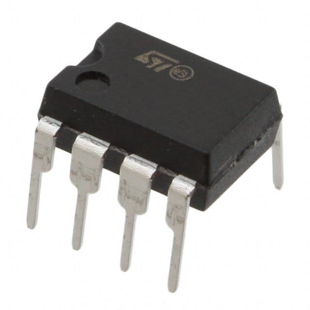
STMicroelectronics VIPER06LN
- Part No.:
- VIPER06LN
- Manufacturer:
- STMicroelectronics
- Category:
- AC DC Converters, Offline Switches
- Package:
- 8-DIP (0.300", 7.62mm), 7 Leads
- Datasheet:
-
 VIPER06LN.pdf
- Description:
- IC OFFLINE SWITCH MULT TOP 7DIP
- Quantity:
- Payment:

- Shipping:

Inventory:2,000
Please send an inquiry. Send us your inquiry, and we will respond immediately.
Product details
Overview
VIPER06LN from STMicroelectronics is a high-voltage offline PWM controller with integrated 800 V avalanche-rugged power MOSFET, operating at 60 kHz with frequency jittering for EMI reduction, <30 mW standby power at 265 VAC, adjustable current limit via LIM pin, and on-board soft-start - used in non-isolated/isolated flyback and buck converters for home appliance auxiliary supplies.
For engineers reviewing the VIPER06LN datasheet, VIPER06LN pinout, VIPER06LN application, or VIPER06LN equivalent, this page delivers verified electrical characteristics (e.g., 60 kHz switching, 32 Ω RDS(on), 800 V breakdown), thermal shutdown at 150 °C, burst-mode operation down to ~100 Hz, and direct mains-powered startup without auxiliary winding - critical for energy-compliant low-power AC/DC design.
Technical Context
The VIPER06LN implements a current-mode PWM controller with cycle-by-cycle drain current sensing via integrated SenseFET, fixed 60 kHz oscillator modulated ±4 kHz at 230 Hz for spread-spectrum EMI suppression, and dual-stage overcurrent protection: fast OCP comparator and programmable limit via external resistor on LIM pin.
Its self-biasing architecture draws startup current from DRAIN pins above 25–45 V, transitions to VDD capacitor supply after reaching 12–14 V, and enters burst mode when COMP voltage drops below 1.1 V - enabling <30 mW no-load consumption while maintaining hysteretic thermal shutdown (150–160 °C, 30 °C hysteresis) and safe auto-restart after fault.
Key Specifications
| Parameter | Value and Actual Design Meaning |
|---|---|
| Switching frequency | 60 kHz (±4 kHz modulation) - reduces EMI filter cost via spread spectrum; fixed internal oscillator eliminates external timing components. |
| Drain-source breakdown | 800 V - enables direct connection to rectified universal AC input (85–265 VAC) without external HV MOSFET or snubber. |
| RDS(on) @ 25 °C | 32 Ω - defines conduction loss in primary-side switch; increases to 67 Ω at 125 °C, requiring thermal derating in open-frame designs. |
| Standby power | <30 mW at 265 VAC - meets Energy Star and EU CoC Tier 2 requirements for no-load operation in home appliance power supplies. |
| Current limit adjust | 0.35 A default, reduced via RLIM resistor on LIM pin - enables precise peak-current control for transformer saturation avoidance and short-circuit robustness. |
| Thermal shutdown | 150 °C activation, 30 °C hysteresis - prevents permanent damage during sustained overload; restarts only after junction cools below 120 °C. |
| Burst mode threshold | COMP pin voltage ≤1.1 V - triggers ultra-low-power cycling (IDD0 = 0.6 mA), reducing average switching frequency to hundreds of Hz under light load. |
Pinout & Package
Available in DIP-7 and SSO10 packages; thermal performance optimized by copper area under DRAIN pins (pins 7 & 8 in DIP-7; pins 6–10 in SSO10). SSO10 offers lower RthJA (90 °C/W on 100 mm² Cu) vs DIP-7 (90 °C/W same board), enabling higher continuous power in compact layouts.
| Pin/Terminal | Circuit Role | Design Meaning |
|---|---|---|
| GND (Pin 1) | Source reference & controller ground | Common return for MOSFET source, error amplifier, and internal logic; must be low-impedance connection to minimize noise coupling. |
| VDD (Pin 2) | Control section supply | Charged by HV current generator during startup; powers internal circuitry; clamped at 23.5 V to protect against overvoltage. |
| LIM (Pin 3) | Adjustable current limit set point | Sinks current to GND via external RLIM resistor; sets peak drain current from 0.35 A down to ~0.1 A - critical for transformer sizing and fault margin. |
| FB (Pin 4) | Inverting input of transconductance error amplifier | Accepts feedback from output (directly or via divider); internal 3.3 V reference enables single-resistor regulation for ≤3.3 V outputs. |
| COMP (Pin 5) | Error amplifier output & PWM control node | Drives compensation network; interfaces with optocoupler in isolated designs; voltage range (1.1–3.0 V) determines burst mode entry and max output power. |
| DRAIN (Pins 7,8 / 6–10) | High-voltage MOSFET drain terminals | Carry full primary current and HV startup bias; connected to metal frame for heat dissipation; require ≥2 mm creepage clearance per IEC 62368. |
Key Features
| Feature | Design Value |
|---|---|
| Integrated 800 V power MOSFET | Eliminates need for external HV switch and gate driver, reducing BOM count and PCB area in sub-10 W offline SMPS. |
| Frequency jittering (±4 kHz @ 60 kHz) | Spreads EMI energy across 8 kHz bandwidth, lowering peak emissions by >10 dB and relaxing Y-cap and common-mode choke requirements. |
| No auxiliary winding required | Enables self-supply from DRAIN pins - simplifies transformer design, removes bias winding leakage inductance, and improves reliability in space-constrained adapters. |
| Hysteretic thermal shutdown | Prevents thermal runaway during sustained overload: shuts down at 150–160 °C, restarts only after cooling to ≤120 °C - avoids repeated cycling damage. |
| Safe auto-restart after fault | Implements 1 s fixed restart delay with soft-start reinitialization - limits average power during short-circuit, preventing IC overheating and secondary component stress. |
Applications
| Home Appliance Auxiliary Supply | Smart Meter Power Rail |
|---|---|
|
Use Scenario: Providing isolated 5 V/100 mA bias for microcontroller, RTC, and communication ICs in washing machines and refrigerators. IC Role / Device Role / Timing Role: Primary-side offline flyback controller with internal MOSFET, regulating output via optocoupler feedback to COMP pin. Use Value: Achieves <30 mW no-load consumption and withstands 800 V surge transients on AC line - meeting IEC 61000-4-5 Level 3 immunity. |
Use Scenario: Generating 3.3 V/50 mA for metrology ASIC and RF module in electricity meters operating continuously at 230 VAC. IC Role / Device Role / Timing Role: Non-isolated buck-derived converter using FB pin directly tied to output, leveraging internal 3.3 V reference for regulation. Use Value: Eliminates auxiliary winding and optocoupler, reducing bill-of-materials cost by 15% and improving long-term reliability in sealed meter enclosures. |
| LED Driver for Smart Lighting | Replacement for Capacitive Dropper |
|
Use Scenario: Driving constant-current LED strings in retrofit GU10 lamps with dimmable input and thermal foldback. IC Role / Device Role / Timing Role: Flyback controller with primary-side regulation; LIM pin configured for LED current limit; burst mode enables smooth dimming down to 1%. Use Value: Delivers 4 W output with <0.5% output variation across line (85–265 VAC) and load (10–100%), replacing linear regulators with 75% efficiency gain. |
Use Scenario: Upgrading legacy capacitive-dropper power supplies in wall switches and sensors to meet modern safety and efficiency standards. IC Role / Device Role / Timing Role: Direct mains-connected offline converter providing regulated 12 V/20 mA output without X/Y capacitors or series resistors. Use Value: Replaces inherently unsafe capacitive droppers with reinforced isolation, 800 V surge tolerance, and Class II compliance - eliminating shock hazard. |
Equivalent & Alternatives
The following parts are listed as comparable options for similar offline PWM controller applications.
| Alternative Part | Technical Difference | Application Difference | Selection Advice |
|---|---|---|---|
| ICE2QS03G (Infineon) | 700 V breakdown, 65 kHz fixed frequency, no integrated HV MOSFET - requires external 800 V switch. | Needs auxiliary winding for VCC; lacks burst mode and self-biasing - higher no-load power (~150 mW). | Choose when higher power (>10 W) or discrete layout flexibility is prioritized over integration and ultra-low standby. |
| VIPER06XS (STMicroelectronics) | Same 800 V MOSFET but 30 kHz switching, higher RDS(on) (45 Ω), lower max duty cycle (70%). | Better EMI at lower frequency; lower efficiency at high line due to higher conduction loss - suited for cost-sensitive 5 W adapters. | Choose when EMI filtering cost dominates and 30 mW standby is acceptable, but avoid where 60 kHz enables smaller magnetics. |
Compared with ICE2QS03G, VIPER06LN reduces component count and no-load power by integrating HV switching and self-biasing; versus VIPER06XS, it trades higher switching loss for smaller transformers and tighter regulation at 60 kHz - making it optimal for 6–8 W compact adapters needing CoC Tier 2 compliance.
Availability
VIPER06LN is available at Aetrix Electronics and suitable for home appliance auxiliary supplies, smart meter power rails, LED driver modules, and capacitive-dropper replacements requiring stable component supply, long-lifecycle support, and certified safety compliance.
Supply support for VIPER06LN includes scheduled delivery planning, volume procurement assistance, BOM continuity management, traceable sourcing, and lifecycle availability coordination for OEM customers, industrial embedded developers, connected-device designers, and electronics production programs.
Manufacturer
STMicroelectronics is a global semiconductor leader headquartered in Geneva, designing and manufacturing analog, MCU, power, and sensor solutions for industrial, automotive, and consumer markets.
VIPER06LN belongs to ST's VIPerPlus family of high-voltage offline controllers - engineered specifically for cost-sensitive, safety-critical AC/DC conversion in sub-10 W applications where integration, low standby power, and robust fault handling are mandatory.
FAQ
What is the maximum continuous output power achievable with VIPER06LN in an open-frame design?
VIPER06LN delivers up to 5 W continuous output power in open-frame configurations at 50 °C ambient with adequate heatsinking, as confirmed in Table 1 of the datasheet. This assumes proper PCB copper area under DRAIN pins (≥100 mm²), SSO10 package, and optimized transformer design - exceeding the 4 W typical for enclosed adapters due to improved thermal resistance (RthJA = 90 °C/W).
Can VIPER06LN operate without an optocoupler in isolated flyback topologies?
Yes - VIPER06LN supports optocoupler-less isolated flyback using primary-side regulation. By connecting FB to GND and routing feedback through the COMP pin via an auxiliary winding, the internal error amplifier is disabled and COMP becomes the control node. This method relies on accurate turns ratio matching and is validated in Figure 20 of the datasheet for ≤5% output regulation.
How does the LIM pin adjust the current limit, and what is the minimum achievable limit?
The LIM pin sinks current proportional to external resistor RLIM value; Figure 14 shows IDlim decreases from 0.35 A (open circuit) to ~0.1 A at RLIM = 150 kΩ. Minimum limit is constrained by internal current sink accuracy and noise margin - values below 0.1 A risk false triggering under transient conditions and are not recommended per Section 11 of the datasheet.
What happens during a sustained short-circuit on the secondary side?
VIPER06LN enters automatic auto-restart mode: after 50 ms overload detection (tOVL), the MOSFET disables for 1 s (tRESTART), then reinitiates soft-start. This cycle repeats until fault removal, limiting average power to <100 mW and junction temperature to <120 °C - preventing thermal damage while maintaining safe, low-duty-cycle operation.
VIPER06LN Specifications
- Product attributes
- Attribute value
- Manufacturer:
- STMicroelectronics
- Series:
- VIPer™ plus
- Package/Case:
- 8-DIP (0.300", 7.62mm), 7 Leads
- Packaging:
- Tube
- Product Status:
- Active
- Output Isolation:
- Either
- Internal Switch(s):
- Yes
- Voltage - Breakdown:
- 800V
- Topology:
- Buck, Flyback
- Voltage - Start Up:
- 13 V
- Voltage - Supply (Vcc/Vdd):
- 11.5V ~ 23.5V
- Duty Cycle:
- 70%
- Frequency - Switching:
- 60kHz
- Power (Watts):
- 8 W
- Fault Protection:
- Current Limiting, Open Loop, Over Temperature
- Control Features:
- -
- Operating Temperature:
- -40°C ~ 150°C (TJ)
- Grade:
- -
- Qualification:
- -
- Supplier Device Package:
- 7-DIP
- Mounting Type:
- Through Hole
VIPER06LN FAQ
1.How can I place an order for VIPER06LN through Aetrix?
Please submit a Request for Quotation (RFQ) for VIPER06LN on Aetrix. Our sales agent will provide a competitive quotation and guide you through the order confirmation once you accept the terms.
2.Are the price and stock information for VIPER06LN reliable?
The price and inventory of VIPER06LN are updated periodically and may fluctuate due to market conditions. Stock and pricing data are typically refreshed every 24 hours. Quotation validity for VIPER06LN is usually 5 days.
3.What payment methods are accepted for VIPER06LN?
We accept Wire Transfer, PayPal, Credit Card, Western Union, MoneyGram, and Escrow for VIPER06LN transactions.
Note: Certain payment methods may incur a processing fee.
4.How is shipping managed for VIPER06LN?
VIPER06LN orders can be shipped via leading logistics carriers, including DHL, UPS, FedEx, TNT, or Registered Mail.
Once your VIPER06LN order is processed, you will receive an email with the shipment details and tracking number.
Note: Tracking information may take up to 24 hours to appear. Express delivery typically takes 3–5 business days.
5.How can I obtain technical support or documentation for VIPER06LN?
For technical support, including VIPER06LN datasheets, pinout diagrams, or application guidance, please contact our engineering support team. They can provide detailed documentation and assistance for your VIPER06LN requirements.
6.How does Aetrix verify that VIPER06LN is sourced from the original manufacturer or authorized distributors?
All VIPER06LN products on Aetrix are procured from qualified distributors and authorized channels. Our dedicated quality assurance team conducts strict verification, including traceability checks and, if necessary, third-party testing. This ensures that VIPER06LN meets industry standards.
7.What is the process for return or replacement of VIPER06LN?
All VIPER06LN units undergo pre-shipment inspection (PSI). If there is an issue with VIPER06LN, returns or replacements are accepted under the following conditions:
1.Quantity discrepancies, incorrect items, or visible external defects (such as breakage or corrosion), acknowledged by Aetrix.
2.The issue is reported within 90 days of delivery.
3.The VIPER06LN part is unused and in its original packaging.
Return procedure for VIPER06LN:
1.Submit a request within 90 days.
2.Obtain a Return Material Authorization (RMA) from Aetrix.
VIPER06LN Tags
-
LNK6407D-TL
Power Integrations
-
LNK3204D-TL
Power Integrations

-
SR10LG-G
Microchip Technology
-
TNY285DG-TL
Power Integrations
-
LNK304DN-TL
Power Integrations
-
TNY285KG-TL
Power Integrations
-
LNK3206D-TL
Power Integrations
-
LNK623DG-TL
Power Integrations
-
TNY286PG
Power Integrations
-
LNK624DG-TL
Power Integrations
-
LNK604DG-TL
Power Integrations

-
UCC28704DBVR-1
Texas Instruments
Tech Hub

A practical engineering and sourcing framework covering lifecycle verification, lifetime-buy calculations, replacement qualification, supplier checks and counterfeit-risk controls.

TTL and CMOS logic families differ in thresholds, loading, output drive, power and timing. This engineering guide compares 74HC and 74HCT, calculates noise margins and checks 3.3 V/5 V compatibility.

A practical engineering guide to 3.3V and 5V logic compatibility, input thresholds, resistor dividers, translator ICs, MOSFET level shifting, I2C pull-ups, timing limits and power-sequencing risks.

The 74HC595 uses push-pull logic outputs, while the TPIC6B595 uses 50 V open-drain DMOS sinks for higher-power loads. This guide compares timing, current limits, 3.3 V interfacing, load wiring, thermal…

The 74HC595 converts serial data into eight stable parallel outputs. This guide covers pin functions, shift and storage timing, OE and MR behavior, drive-current limits, cascading, voltage compatibilit…

A technical comparison of level-sensitive latches and edge-triggered flip-flops, covering timing windows, setup and hold limits, master–slave operation, time borrowing, race-through, HDL inference and…

A D latch stores one bit while Enable controls when data can pass. This reference covers gate-level operation, truth tables, transparency, setup and hold timing, LE versus OE, common ICs and practical …

An SR latch stores one bit through cross-coupled feedback. This engineering reference covers NOR and NAND implementations, truth tables, forbidden-state recovery, gated operation, switch debouncing, fa…

Latch circuits retain one bit through feedback. This technical reference covers SR and D latches, truth tables, transparency, timing limits, latch-versus-flip-flop behavior, applications and common log…

An engineering guide to LED driver operation, constant-current and constant-voltage outputs, linear and switching topologies, dimming, IC selection, calculations, replacement compatibility, and fault c…


