
 My Inquiry
 My Account


STMicroelectronics VIPER06LSTR
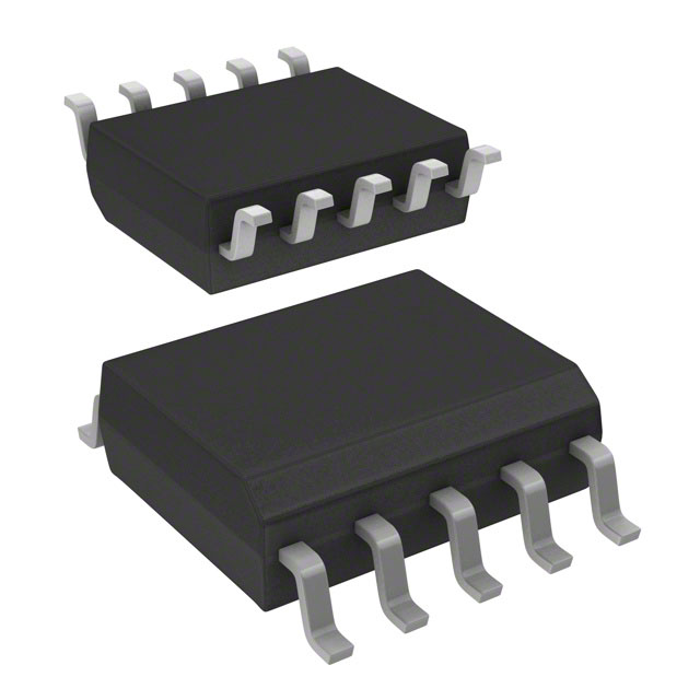
- Part No.:
- VIPER06LSTR
- Manufacturer:
- STMicroelectronics
- Category:
- AC DC Converters, Offline Switches
- Package:
- 10-SOP (0.154", 3.90mm Width)
- Datasheet:
-
 VIPER06LSTR.pdf
- Description:
- IC OFFLINE SWITCH MULT TOP 10SSO
- Quantity:
- Payment:

- Shipping:

Inventory:19,072
Please send an inquiry. Send us your inquiry, and we will respond immediately.
Product details
Overview
VIPER06LSTR from STMicroelectronics is a high-voltage offline flyback controller IC with integrated 800 V avalanche-rugged power MOSFET, fixed 60 kHz switching frequency, <30 mW standby power at 265 VAC, and adjustable current limiting via the LIM pin. It enables self-biased, auxiliary-winding-free power supplies for low-power AC/DC conversion in home appliance control boards and LED drivers.
For engineers reviewing the VIPER06LSTR datasheet, VIPER06LSTR pinout, VIPER06LSTR application, or VIPER06LSTR equivalent, key selection criteria include its 800 V drain rating, internal soft-start, burst-mode operation for energy compliance, thermal shutdown hysteresis, and direct mains-powered startup without auxiliary winding.
Technical Context
The VIPER06LSTR integrates a current-mode PWM controller with a SenseFET-based drain current sensing path and an internal transconductance error amplifier referenced to 3.3 V on the FB pin. Its oscillator delivers fixed 60 kHz switching with ±4 kHz jitter at 230 Hz to reduce EMI peak emissions.
Startup is managed by a high-voltage current generator sourcing −1.8 mA from DRAIN pins until VDD reaches 12–14 V; thereafter, operation transitions to VDD capacitor supply. Fault handling includes hysteretic thermal shutdown (150–160 °C), safe auto-restart after overload (1 s restart delay), and open-loop failure detection via VDD clamp monitoring.
Key Specifications
| Parameter | Value and Actual Design Meaning |
|---|---|
| Switching frequency | 60 kHz (fixed, ±4 kHz jitter) - enables compact magnetics and predictable EMI spread-spectrum filtering |
| Drain breakdown voltage | 800 V - supports direct rectified mains input up to 380 VDC without external HV protection |
| Standby power | <30 mW at 265 VAC - meets EU CoC Tier 2 and DOE Level VI no-load efficiency requirements |
| Current limit adjust | Set via external resistor on LIM pin - allows precise peak drain current tuning from default 350 mA down to lower values |
| FB reference voltage | 3.3 V (±3%) - defines output regulation point for non-isolated designs using single-resistor feedback |
| Thermal shutdown | Hysteretic at 150–160 °C (30 °C hysteresis) - prevents thermal runaway while enabling automatic recovery after cooling |
| Burst mode threshold | VCOMP = 1.1 V ±0.1 V - triggers ultra-low-power cycling under light load to minimize no-load losses |
Pinout & Package
The VIPER06LSTR is housed in a surface-mount SSO10 package with exposed metal pad for thermal dissipation; DRAIN pins (6–10) are internally bonded to the metal frame and must be connected to large copper areas on PCB for effective heat transfer.
| Pin/Terminal | Circuit Role | Design Meaning |
|---|---|---|
| GND (Pin 1) | Power MOSFET source & controller ground reference | Common return for all internal circuitry; must be low-impedance connection to minimize noise coupling into error amplifier |
| VDD (Pin 2) | Control section supply input | Charged by internal HV generator during startup; clamped at 23.5 V; powers all logic and gate drive circuits |
| LIM (Pin 3) | Adjustable overcurrent limit set point | Sinks current to GND via external resistor; sets reduced peak drain current threshold for fault margin tuning |
| FB (Pin 4) | Inverting input of transconductance error amplifier | Accepts feedback voltage; regulates output by comparing to internal 3.3 V reference; includes internal pull-up if floating |
| COMP (Pin 5) | Error amplifier output & PWM comparator input | Drives external RC compensation network; also interfaces with optocoupler in isolated topologies; range 1.1–3.0 V |
| DRAIN (Pins 6–10) | High-voltage power MOSFET drain terminals | Carry full primary-side switching current; source HV startup bias current; require thermal copper pour under package |
Key Features
| Feature | Design Value |
|---|---|
| Integrated 800 V power MOSFET | Eliminates need for external HV switch and associated gate drive complexity in sub-10 W offline converters |
| Self-biasing startup | Draws initial current directly from DRAIN pins - removes auxiliary winding and associated transformer taps |
| Frequency jittering | ±4 kHz modulation at 230 Hz spreads EMI energy across spectrum - reduces peak filter attenuation requirements |
| On-chip soft-start | 8.5 ms controlled ramp of current limit - prevents transformer saturation and secondary diode overstress at power-on |
| Burst-mode operation | Reduces average switching frequency to ~few hundred Hz under light load - cuts core loss, conduction loss, and audible noise |
Applications
| Smart Home Power Supply | LED Driver for Indoor Lighting |
|---|---|
Use Scenario: Standby power supply for Wi-Fi-enabled thermostats and smart plugs operating continuously at <30 mW no-load consumption. IC Role / Device Role / Timing Role: Primary-side controller and HV switch in non-isolated flyback topology; regulates 5 V/3.3 V rail directly from rectified mains. Use Value: Meets stringent energy regulations (IEC 62301 Class I) without auxiliary winding or external HV startup circuitry. | Use Scenario: Constant-voltage driver powering 12 V LED strips in residential ceiling fixtures with dimming compatibility. IC Role / Device Role / Timing Role: Integrated controller/MOSFET managing primary-side regulation and cycle-by-cycle current limiting in isolated flyback configuration. Use Value: Enables compact, cost-effective design with <1% output voltage deviation across line/load variations and built-in short-circuit protection. |
| Electric Meter Auxiliary Supply | Appliance Control Board Power |
Use Scenario: Mains-derived auxiliary power for microcontroller, RTC, and communication modules in smart electricity meters. IC Role / Device Role / Timing Role: Offline converter delivering regulated 3.3 V from 230 VAC input; operates in burst mode during meter sleep cycles. Use Value: Achieves <30 mW standby draw while maintaining reliable start-up across wide temperature range (−40 to +85 °C). | Use Scenario: Embedded power supply for control logic in washing machine mainboard, requiring robustness against motor-induced line transients. IC Role / Device Role / Timing Role: High-voltage flyback controller with 800 V drain rating and thermal foldback, protecting against sustained overloads during spin cycles. Use Value: Survives repeated 600 V line surges without external TVS; auto-restarts safely after transient overloads without firmware intervention. |
Equivalent & Alternatives
The following parts are listed as comparable options for similar offline flyback controller applications.
| Alternative Part | Technical Difference | Application Difference | Selection Advice |
|---|---|---|---|
| ICE2QS03G | Fixed 65 kHz frequency; requires external HV startup resistor; no integrated MOSFET - needs discrete 650 V switch | Higher BOM count and layout complexity; better suited for designs needing tighter EMI control via external frequency sync | Select when board space allows discrete HV switch and design requires programmable soft-start timing |
| LNK306P | 725 V MOSFET; 66 kHz operation; integrated X-capacitor discharge; no LIM pin - fixed current limit only | Lacks adjustable overcurrent threshold; includes safety-certified X-cap discharge path - preferred for UL/EN62368-1 certified end products | Choose for safety-critical consumer appliances where integrated X-cap discharge and certification support are mandatory |
Compared with ICE2QS03G and LNK306P, the VIPER06LSTR offers the lowest system-level component count due to its integrated 800 V MOSFET and self-biasing startup, while providing unique LIM-pin current limit adjustability - critical for optimizing transformer utilization and fault margin in cost-sensitive industrial controls.
Availability
VIPER06LSTR is available at Aetrix Electronics and suitable for smart home power supplies, LED lighting drivers, electric meter auxiliary supplies, and appliance control board power requiring stable component supply across extended product lifecycles.
Supply support for VIPER06LSTR includes scheduled delivery planning, volume procurement assistance, BOM continuity management, traceable sourcing, and lifecycle availability coordination for OEM customers, industrial embedded developers, connected-device designers, and electronics production programs.
Manufacturer
STMicroelectronics is a global semiconductor leader headquartered in Geneva, Switzerland, designing and manufacturing microcontrollers, power ICs, sensors, and analog devices for industrial, automotive, and consumer markets.
The VIPER series targets cost-sensitive, low-to-mid power AC/DC conversion, emphasizing integration, energy efficiency, and robustness in mains-connected applications without auxiliary windings.
FAQ
What is the maximum continuous output power achievable with VIPER06LSTR in an open-frame design?
At 50 °C ambient with adequate heatsinking, the VIPER06LSTR delivers up to 5 W continuously in open-frame configurations. This is limited by thermal resistance (RthJA = 90 °C/W on standard FR4) and internal power dissipation constraints - exceeding this requires forced air or enhanced copper pour to maintain junction temperature below 150 °C.
Can VIPER06LSTR operate in isolated flyback topologies without an optocoupler?
Yes - it supports optocoupler-less isolated flyback using primary-side regulation (PSR) techniques. The FB pin is shorted to GND to disable the internal error amplifier, and regulation is achieved by sampling reflected auxiliary winding voltage during MOSFET off-time, leveraging the COMP pin's dynamic range and burst-mode behavior for stability.
How does the LIM pin adjustment affect short-circuit protection response time?
Reducing the current limit via the LIM pin lowers the peak drain current threshold but does not change the overload timer (tOVL = 50 ms) or restart delay (tRESTART = 1 s). However, a lower IDlim causes earlier current-limit activation during faults, reducing energy per cycle and lowering thermal stress on the internal MOSFET during sustained short-circuit events.
Is the 800 V drain rating valid for repetitive avalanche conditions?
Yes - the datasheet specifies 2 mJ repetitive avalanche energy (EAV) and 1 A repetitive avalanche current (IAR) at TJ = 150 °C. This rating enables reliable operation during line surges and transformer leakage inductance spikes without external snubbers, provided layout minimizes parasitic inductance in the DRAIN loop.
VIPER06LSTR Specifications
- Product attributes
- Attribute value
- Manufacturer:
- STMicroelectronics
- Series:
- VIPer™ plus
- Package/Case:
- 10-SOP (0.154", 3.90mm Width)
- Packaging:
- Tape & Reel (TR)
- Product Status:
- Active
- Output Isolation:
- Either
- Internal Switch(s):
- Yes
- Voltage - Breakdown:
- 800V
- Topology:
- Buck, Flyback
- Voltage - Start Up:
- 13 V
- Voltage - Supply (Vcc/Vdd):
- 11.5V ~ 23.5V
- Duty Cycle:
- 70%
- Frequency - Switching:
- 60kHz
- Power (Watts):
- 8 W
- Fault Protection:
- Current Limiting, Open Loop, Over Temperature
- Control Features:
- -
- Operating Temperature:
- -40°C ~ 150°C (TJ)
- Grade:
- -
- Qualification:
- -
- Supplier Device Package:
- 10-SSOP
- Mounting Type:
- Surface Mount
VIPER06LSTR FAQ
1.How can I place an order for VIPER06LSTR through Aetrix?
Please submit a Request for Quotation (RFQ) for VIPER06LSTR on Aetrix. Our sales agent will provide a competitive quotation and guide you through the order confirmation once you accept the terms.
2.Are the price and stock information for VIPER06LSTR reliable?
The price and inventory of VIPER06LSTR are updated periodically and may fluctuate due to market conditions. Stock and pricing data are typically refreshed every 24 hours. Quotation validity for VIPER06LSTR is usually 5 days.
3.What payment methods are accepted for VIPER06LSTR?
We accept Wire Transfer, PayPal, Credit Card, Western Union, MoneyGram, and Escrow for VIPER06LSTR transactions.
Note: Certain payment methods may incur a processing fee.
4.How is shipping managed for VIPER06LSTR?
VIPER06LSTR orders can be shipped via leading logistics carriers, including DHL, UPS, FedEx, TNT, or Registered Mail.
Once your VIPER06LSTR order is processed, you will receive an email with the shipment details and tracking number.
Note: Tracking information may take up to 24 hours to appear. Express delivery typically takes 3–5 business days.
5.How can I obtain technical support or documentation for VIPER06LSTR?
For technical support, including VIPER06LSTR datasheets, pinout diagrams, or application guidance, please contact our engineering support team. They can provide detailed documentation and assistance for your VIPER06LSTR requirements.
6.How does Aetrix verify that VIPER06LSTR is sourced from the original manufacturer or authorized distributors?
All VIPER06LSTR products on Aetrix are procured from qualified distributors and authorized channels. Our dedicated quality assurance team conducts strict verification, including traceability checks and, if necessary, third-party testing. This ensures that VIPER06LSTR meets industry standards.
7.What is the process for return or replacement of VIPER06LSTR?
All VIPER06LSTR units undergo pre-shipment inspection (PSI). If there is an issue with VIPER06LSTR, returns or replacements are accepted under the following conditions:
1.Quantity discrepancies, incorrect items, or visible external defects (such as breakage or corrosion), acknowledged by Aetrix.
2.The issue is reported within 90 days of delivery.
3.The VIPER06LSTR part is unused and in its original packaging.
Return procedure for VIPER06LSTR:
1.Submit a request within 90 days.
2.Obtain a Return Material Authorization (RMA) from Aetrix.
VIPER06LSTR Tags
-
LNK6407D-TL
Power Integrations
-
LNK3204D-TL
Power Integrations

-
SR10LG-G
Microchip Technology
-
TNY285DG-TL
Power Integrations
-
LNK304DN-TL
Power Integrations
-
TNY285KG-TL
Power Integrations
-
LNK3206D-TL
Power Integrations
-
LNK623DG-TL
Power Integrations
-
TNY286PG
Power Integrations
-
LNK624DG-TL
Power Integrations
-
LNK604DG-TL
Power Integrations

-
UCC28704DBVR-1
Texas Instruments
Tech Hub

A practical engineering and sourcing framework covering lifecycle verification, lifetime-buy calculations, replacement qualification, supplier checks and counterfeit-risk controls.

TTL and CMOS logic families differ in thresholds, loading, output drive, power and timing. This engineering guide compares 74HC and 74HCT, calculates noise margins and checks 3.3 V/5 V compatibility.

A practical engineering guide to 3.3V and 5V logic compatibility, input thresholds, resistor dividers, translator ICs, MOSFET level shifting, I2C pull-ups, timing limits and power-sequencing risks.

The 74HC595 uses push-pull logic outputs, while the TPIC6B595 uses 50 V open-drain DMOS sinks for higher-power loads. This guide compares timing, current limits, 3.3 V interfacing, load wiring, thermal…

The 74HC595 converts serial data into eight stable parallel outputs. This guide covers pin functions, shift and storage timing, OE and MR behavior, drive-current limits, cascading, voltage compatibilit…

A technical comparison of level-sensitive latches and edge-triggered flip-flops, covering timing windows, setup and hold limits, master–slave operation, time borrowing, race-through, HDL inference and…

A D latch stores one bit while Enable controls when data can pass. This reference covers gate-level operation, truth tables, transparency, setup and hold timing, LE versus OE, common ICs and practical …

An SR latch stores one bit through cross-coupled feedback. This engineering reference covers NOR and NAND implementations, truth tables, forbidden-state recovery, gated operation, switch debouncing, fa…

Latch circuits retain one bit through feedback. This technical reference covers SR and D latches, truth tables, transparency, timing limits, latch-versus-flip-flop behavior, applications and common log…

An engineering guide to LED driver operation, constant-current and constant-voltage outputs, linear and switching topologies, dimming, IC selection, calculations, replacement compatibility, and fault c…


