
 My Inquiry
 My Account


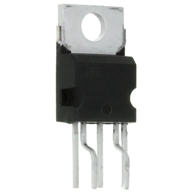
STMicroelectronics VIPER20A-E
- Part No.:
- VIPER20A-E
- Manufacturer:
- STMicroelectronics
- Category:
- AC DC Converters, Offline Switches
- Package:
- Pentawatt-5 HV (Bent and Staggered Leads)
- Datasheet:
-
 VIPER20A-E.pdf
- Description:
- IC OFFLIN CONV FLBACK 5PENTAWATT
- Quantity:
- Payment:

- Shipping:

Inventory:4,526
Please send an inquiry. Send us your inquiry, and we will respond immediately.
Product details
Overview
VIPER20A-E from STMicroelectronics is a 700 V, 0.5 A integrated primary-side SMPS controller combining a current-mode PWM controller and a vertical high-voltage Power MOSFET in a single PENTAWATT HV package. It delivers up to 10 W in universal-input offline power supplies, features adjustable 90–110 kHz switching frequency, internal 13 V VDD regulation, and burst-mode operation enabling <1 W standby consumption compliant with the German Blue Angel standard.
For engineers reviewing the VIPER20A-E datasheet, VIPER20A-E pinout, VIPER20A-E application, or VIPER20A-E equivalent, key selection considerations include its integrated start-up current source, programmable peak current limit (0.5–0.9 A), thermal shutdown at 140–190 °C, and compatibility with both primary- and secondary-side regulation topologies without external bias windings.
Technical Context
The VIPER20A-E implements current-mode control using an internal transconductance error amplifier (Gm = 1.1–1.9 mA/V) and a dedicated current-sense comparator with 250 ns blanking time and 350–1200 ns minimum on-time. Its oscillator supports external RT/CT programming and synchronization via the OSC pin, maintaining stable 90–110 kHz operation across VDD = 9–15 V.
It integrates a 700 V vertical Power MOSFET with RDS(on) = 15.5–32 Ω (TJ = 25–100 °C), undervoltage lockout with 3 V hysteresis (VDDon = 11–12 V, VDDoff = 7.5–9 V), and overtemperature protection with 40 °C hysteresis. Standby mode is autonomously triggered when VCOMP falls below 0.5 V, forcing zero-duty-cycle burst operation.
Key Specifications
| Parameter | Value and Actual Design Meaning |
|---|---|
| VDS Rating | 700 V - Enables direct connection to universal AC mains (85–265 VAC) without external voltage clamping |
| ID Peak Limit | 0.5–0.9 A - Internally set current threshold defining maximum primary peak current for overload and short-circuit protection |
| FSW Range | 90–110 kHz - Programmable via external RT/CT; stable across VDD variation, enabling EMI optimization |
| VDD Regulation | 12.6–13.4 V - Internally trimmed reference ensures stable low-voltage supply for control circuitry during normal operation |
| Thermal Shutdown | 140–190 °C - Self-protects against sustained overloads or poor heatsinking; 40 °C hysteresis prevents oscillation near trip point |
| Standby Power | <1 W - Achieved via automatic burst mode triggered by COMP < 0.5 V; meets Blue Angel eco-label requirement |
| RDS(on) | 15.5–32 Ω - On-resistance determines conduction loss and thermal rise at full load; specified at 100 °C junction |
Pinout & Package
PENTAWATT HV (15.4 × 10.0 mm, 5-pin, heat sink tab on backside) - thermally optimized for through-hole mounting with direct PCB copper pour contact to drain-source thermal path.
| Pin/Terminal | Circuit Role | Design Meaning |
|---|---|---|
| DRAIN | Integrated Power MOSFET drain | High-voltage input node; supplies internal start-up current source during initial charge of VDD capacitor |
| SOURCE | Power MOSFET source | Primary-side ground reference; connects to transformer primary return and current-sense resistor |
| VDD | Control supply & error amplifier reference | Provides regulated 13 V supply; also serves as feedback node for primary regulation or optocoupler interface in secondary regulation |
| COMP | Error amplifier output & shutdown control | Transconductance output (0.2–4.5 V swing); falling below 0.5 V forces zero-duty-cycle burst mode |
| OSC | Oscillator timing & sync input | Accepts external RT/CT network for frequency setting; also accepts external clock signal for synchronization |
Key Features
| Feature | Design Value |
|---|---|
| Integrated HV Start-up Current Source | Eliminates need for external high-voltage resistor network; reduces no-load power and component count |
| Current-Mode Control with Blanking | 250 ns blanking window prevents false turn-off from transformer leakage spikes or rectifier reverse recovery noise |
| Programmable Burst Mode Threshold | VCOMP < 0.5 V triggers autonomous zero-duty-cycle operation-no external logic or enable pin required |
| Primary/Secondary Regulation Flexibility | VDD pin doubles as regulation reference: 13 V internal reference for primary; optocoupler-compatible for secondary |
| Thermal Protection with Hysteresis | 140–190 °C trip range + 40 °C hysteresis avoids cycling near thermal limit during transient overload |
Applications
| Smart Home Power Adapters | Industrial Sensor Transmitters |
|---|---|
|
Use Scenario: 5 V/1 A USB-C adapter for battery-powered IoT gateways operating across 85–265 VAC mains. IC Role / Device Role / Timing Role: Primary-side SMPS controller managing transformer primary switching, feedback regulation, and burst-mode standby. Use Value: Integrated 700 V MOSFET and start-up source reduce BOM by ≥4 components versus discrete solutions; <1 W standby satisfies EU CoC Tier 2. |
Use Scenario: 24 V DC-powered 4–20 mA loop-powered sensor transmitter with isolated auxiliary supply. IC Role / Device Role / Timing Role: Auxiliary offline converter generating isolated 5 V for microcontroller and analog front-end from 24 V input. Use Value: Adjustable FSW enables EMI filtering at 100 kHz; COMP pin supports precise current-loop regulation via optocoupler feedback. |
| White Goods Control Boards | Medical Auxiliary Supplies |
|
Use Scenario: Standby power supply for refrigerator mainboard, powering MCU and real-time clock during door-open events. IC Role / Device Role / Timing Role: Low-power offline SMPS delivering 3.3 V/100 mA with automatic transition to burst mode at <50 mW load. Use Value: Internal UVLO hysteresis (3 V) ensures clean restart after brownout; thermal shutdown protects against enclosure overheating. |
Use Scenario: Isolated 12 V/500 mA auxiliary supply for patient-monitor front-panel display and touch controller. IC Role / Device Role / Timing Role: Primary-side regulated flyback controller meeting IEC 60601-1 creepage/clearance requirements via reinforced insulation design. Use Value: RDS(on) = 18 Ω (typ.) limits conduction loss at 100 °C; PENTAWATT HV package allows >8 mm creepage across primary-secondary barrier. |
Equivalent & Alternatives
The following parts are listed as comparable options for similar primary-side SMPS controller applications.
| Alternative Part | Technical Difference | Application Difference | Selection Advice |
|---|---|---|---|
| ICE2QS03G | Fixed 65 kHz frequency; no integrated start-up current source; requires external HV resistor | Lacks burst-mode auto-trigger; needs external circuitry for <1 W standby compliance | Prefer when cost sensitivity outweighs standby efficiency and BOM reduction |
| LNK304P | 725 V rating; 0.24 A current limit; smaller SO-8 package; no OSC sync capability | Lower power capability (~6.5 W); no external frequency synchronization option | Choose for space-constrained designs where 100 kHz EMI tuning is not required |
Compared with ICE2QS03G and LNK304P, the VIPER20A-E uniquely combines integrated HV start-up, programmable burst-mode entry, and OSC synchronization-enabling simpler, more robust, and globally compliant offline power designs up to 10 W.
Availability
VIPER20A-E is available at Aetrix Electronics and suitable for smart home adapters, industrial sensor transmitters, white goods control boards, and medical auxiliary supplies requiring stable component supply, long-term lifecycle support, and Blue Angel-compliant standby performance.
Supply support for VIPER20A-E includes scheduled delivery planning, volume procurement assistance, BOM continuity management, traceable sourcing, and lifecycle availability coordination for OEM customers, industrial embedded developers, connected-device designers, and electronics production programs.
Manufacturer
STMicroelectronics is a global semiconductor leader headquartered in Geneva, Switzerland, designing and manufacturing microcontrollers, power ICs, sensors, and automotive-grade components.
The VIPer™ family targets cost-sensitive, high-reliability offline SMPS applications-integrating HV MOSFETs and controllers to replace discrete solutions in sub-25 W power supplies.
FAQ
What is the minimum recommended VDD capacitor value for reliable startup?
The minimum VDD capacitor (CVDD) must satisfy CVDD > (IDD1 × tSS) / VDDhyst, where IDD1 = 13 mA (at 100 kHz), tSS is worst-case startup time (typically 50–100 ms), and VDDhyst = 2.4 V min. For tSS = 80 ms, CVDD > 430 µF. A 470 µF/25 V electrolytic capacitor is commonly used with low-ESR characteristics.
Can VIPER20A-E operate with primary-side regulation only-no optocoupler?
Yes. The device supports primary-side regulation by connecting a resistive divider from the auxiliary winding to the VDD pin. When VDD rises above 13.4 V, the internal regulator clamps it, and the error amplifier's output (COMP) adjusts duty cycle to maintain regulation-eliminating optocoupler, TL431, and associated compensation components.
How does the blanking time affect safe operation at high line voltage?
The fixed 250–360 ns blanking time prevents false current-sense triggering from parasitic ringing during MOSFET turn-on. At 265 VAC input, primary di/dt is highest; insufficient blanking would cause premature switch-off and instability. This built-in delay ensures robust operation without external RC snubbers on the sense resistor.
Is external slope compensation required for continuous conduction mode (CCM)?
Yes, when operating above 50% duty cycle in CCM, external slope compensation is required to prevent subharmonic oscillation. A sawtooth waveform injected into the COMP pin-derived from the OSC pin via a resistor and transistor-adds artificial ramp to the current-sense signal, restoring loop stability per IEEE 1547 guidelines.
VIPER20A-E Specifications
- Product attributes
- Attribute value
- Manufacturer:
- STMicroelectronics
- Series:
- VIPER™
- Package/Case:
- Pentawatt-5 HV (Bent and Staggered Leads)
- Packaging:
- Tube
- Product Status:
- Obsolete
- Output Isolation:
- Isolated
- Internal Switch(s):
- Yes
- Voltage - Breakdown:
- 700V
- Topology:
- Flyback
- Voltage - Start Up:
- 11 V
- Voltage - Supply (Vcc/Vdd):
- 8V ~ 15V
- Duty Cycle:
- -
- Frequency - Switching:
- Up to 200kHz
- Power (Watts):
- 20 W
- Fault Protection:
- Current Limiting, Over Temperature
- Control Features:
- -
- Operating Temperature:
- -
- Grade:
- -
- Qualification:
- -
- Supplier Device Package:
- 5-PENTAWATT
- Mounting Type:
- Through Hole
VIPER20A-E FAQ
1.How can I place an order for VIPER20A-E through Aetrix?
Please submit a Request for Quotation (RFQ) for VIPER20A-E on Aetrix. Our sales agent will provide a competitive quotation and guide you through the order confirmation once you accept the terms.
2.Are the price and stock information for VIPER20A-E reliable?
The price and inventory of VIPER20A-E are updated periodically and may fluctuate due to market conditions. Stock and pricing data are typically refreshed every 24 hours. Quotation validity for VIPER20A-E is usually 5 days.
3.What payment methods are accepted for VIPER20A-E?
We accept Wire Transfer, PayPal, Credit Card, Western Union, MoneyGram, and Escrow for VIPER20A-E transactions.
Note: Certain payment methods may incur a processing fee.
4.How is shipping managed for VIPER20A-E?
VIPER20A-E orders can be shipped via leading logistics carriers, including DHL, UPS, FedEx, TNT, or Registered Mail.
Once your VIPER20A-E order is processed, you will receive an email with the shipment details and tracking number.
Note: Tracking information may take up to 24 hours to appear. Express delivery typically takes 3–5 business days.
5.How can I obtain technical support or documentation for VIPER20A-E?
For technical support, including VIPER20A-E datasheets, pinout diagrams, or application guidance, please contact our engineering support team. They can provide detailed documentation and assistance for your VIPER20A-E requirements.
6.How does Aetrix verify that VIPER20A-E is sourced from the original manufacturer or authorized distributors?
All VIPER20A-E products on Aetrix are procured from qualified distributors and authorized channels. Our dedicated quality assurance team conducts strict verification, including traceability checks and, if necessary, third-party testing. This ensures that VIPER20A-E meets industry standards.
7.What is the process for return or replacement of VIPER20A-E?
All VIPER20A-E units undergo pre-shipment inspection (PSI). If there is an issue with VIPER20A-E, returns or replacements are accepted under the following conditions:
1.Quantity discrepancies, incorrect items, or visible external defects (such as breakage or corrosion), acknowledged by Aetrix.
2.The issue is reported within 90 days of delivery.
3.The VIPER20A-E part is unused and in its original packaging.
Return procedure for VIPER20A-E:
1.Submit a request within 90 days.
2.Obtain a Return Material Authorization (RMA) from Aetrix.
VIPER20A-E Tags
-
LNK6407D-TL
Power Integrations
-
LNK3204D-TL
Power Integrations

-
SR10LG-G
Microchip Technology
-
TNY285DG-TL
Power Integrations
-
LNK304DN-TL
Power Integrations
-
TNY285KG-TL
Power Integrations
-
LNK3206D-TL
Power Integrations
-
LNK623DG-TL
Power Integrations
-
TNY286PG
Power Integrations
-
LNK624DG-TL
Power Integrations
-
LNK604DG-TL
Power Integrations

-
UCC28704DBVR-1
Texas Instruments
Tech Hub

A practical engineering and sourcing framework covering lifecycle verification, lifetime-buy calculations, replacement qualification, supplier checks and counterfeit-risk controls.

TTL and CMOS logic families differ in thresholds, loading, output drive, power and timing. This engineering guide compares 74HC and 74HCT, calculates noise margins and checks 3.3 V/5 V compatibility.

A practical engineering guide to 3.3V and 5V logic compatibility, input thresholds, resistor dividers, translator ICs, MOSFET level shifting, I2C pull-ups, timing limits and power-sequencing risks.

The 74HC595 uses push-pull logic outputs, while the TPIC6B595 uses 50 V open-drain DMOS sinks for higher-power loads. This guide compares timing, current limits, 3.3 V interfacing, load wiring, thermal…

The 74HC595 converts serial data into eight stable parallel outputs. This guide covers pin functions, shift and storage timing, OE and MR behavior, drive-current limits, cascading, voltage compatibilit…

A technical comparison of level-sensitive latches and edge-triggered flip-flops, covering timing windows, setup and hold limits, master–slave operation, time borrowing, race-through, HDL inference and…

A D latch stores one bit while Enable controls when data can pass. This reference covers gate-level operation, truth tables, transparency, setup and hold timing, LE versus OE, common ICs and practical …

An SR latch stores one bit through cross-coupled feedback. This engineering reference covers NOR and NAND implementations, truth tables, forbidden-state recovery, gated operation, switch debouncing, fa…

Latch circuits retain one bit through feedback. This technical reference covers SR and D latches, truth tables, transparency, timing limits, latch-versus-flip-flop behavior, applications and common log…

An engineering guide to LED driver operation, constant-current and constant-voltage outputs, linear and switching topologies, dimming, IC selection, calculations, replacement compatibility, and fault c…


