
 My Inquiry
 My Account


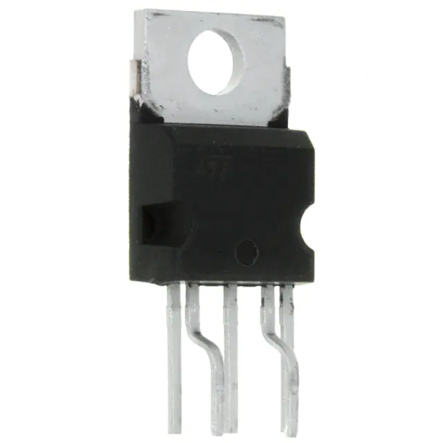
STMicroelectronics VIPER50A-E
- Part No.:
- VIPER50A-E
- Manufacturer:
- STMicroelectronics
- Category:
- AC DC Converters, Offline Switches
- Package:
- Pentawatt-5 HV (Bent and Staggered Leads)
- Datasheet:
-
 VIPER50A-E.pdf
- Description:
- IC OFFLIN CONV FLBACK 5PENTAWATT
- Quantity:
- Payment:

- Shipping:

Inventory:3,563
Please send an inquiry. Send us your inquiry, and we will respond immediately.
Product details
Overview
VIPER50A-E from STMicroelectronics is a high-voltage, current-mode PWM controller with integrated 700 V vertical power MOSFET, designed for primary-side switching in offline SMPS. It delivers up to 50 W in single-range configurations, features adjustable 90–110 kHz switching frequency, internal 13 V VDD regulation, and burst-mode operation enabling <1 W standby consumption per Blue Angel norm.
For engineers reviewing the VIPER50A-E datasheet, VIPER50A-E pinout, VIPER50A-E application, or VIPER50A-E equivalent, key selection considerations include its integrated start-up current source, 1.5 A peak current limit, 5.7 Ω RDS(on) at 100°C, thermal shutdown at 140–170°C, and compatibility with both primary- and secondary-side regulation topologies.
Technical Context
The VIPER50A-E implements a current-mode control architecture with inner current-sense loop and outer voltage regulation loop, using a transconductance error amplifier (Gm = 1.5 mA/V) and integrated blanking time (250–360 ns) to suppress noise-induced false triggering. Its oscillator supports external synchronization via the OSC pin and maintains stable frequency (±10% variation) across VDD = 9–15 V with RT = 8.2 kΩ and CT = 2.4 nF.
Startup relies on an internal high-voltage current source connected to the DRAIN pin, automatically disabling once VDD reaches 11 V (UVLO reset threshold); undervoltage lockout re-engages below 8 V (hysteresis = 3 V). Overtemperature protection triggers at 140–170°C with 40°C hysteresis, forcing latch-off until junction temperature falls below trip-minus-hysteresis.
Key Specifications
| Parameter | Value and Actual Design Meaning |
|---|---|
| VDS Rating | 700 V - Enables direct connection to universal AC mains (85–265 VAC) without external HV startup network. |
| RDS(on) | 5.7 Ω @ Tj = 100°C - Determines conduction loss and thermal rise in continuous conduction mode at full load. |
| IDPEAK | 2 A typical - Sets maximum primary current limit; adjustable externally via COMP pin voltage scaling. |
| FSW | 100 kHz typical (90–110 kHz range) - Balances EMI performance, transformer size, and MOSFET switching loss. |
| VDD Reg | 13 V ±2% - Provides stable low-voltage rail for internal logic and enables optocoupler-based secondary regulation. |
| TSD | 140–170°C - Thermal shutdown threshold ensures safe operation under overload or poor heatsinking conditions. |
| IQ(STBY) | <2 mA - Enables ultra-low-power burst-mode operation meeting Blue Angel <1 W system standby requirement. |
Pinout & Package
Package: PENTAWATT HV (022Y), 5-pin through-hole package with isolated heatsink tab; thermal resistance RthJC = 1.9 °C/W.
| Pin/Terminal | Circuit Role | Design Meaning |
|---|---|---|
| DRAIN | Integrated MOSFET drain terminal | Connects directly to AC rectified input; supplies internal startup current and handles 700 V blocking. |
| SOURCE | MOSFET source / power ground | Primary-side return path; referenced for current sensing and gate drive; requires low-inductance layout. |
| VDD | Low-voltage supply & error amp reference | Provides bias for control circuitry; regulates at 13 V; accepts feedback from auxiliary winding or optocoupler. |
| COMP | Error amplifier output & shutdown control | Drives compensation network; pulls low (<0.5 V) to force zero-duty-cycle burst mode or external shutdown. |
| OSC | Oscillator timing & sync input | Accepts external RC network (RT/CT) for frequency setting; supports external clock synchronization signal. |
Key Features
| Feature | Design Value |
|---|---|
| Integrated 700 V Power MOSFET | Eliminates need for external HV switch and gate driver, reducing BOM count and PCB area in <50 W flyback designs. |
| Internal HV Startup Current Source | Draws bias directly from DRAIN pin during startup-no auxiliary winding required for initial VDD charging. |
| Burst Mode Standby Operation | Automatically engages when output power drops below ~0.5 W, achieving <1 W total system standby per Blue Angel norm. |
| Current-Mode Control with Blanking | 250 ns blanking window prevents false turn-off from transformer leakage spikes or diode reverse recovery noise. |
| Transconductance Error Amplifier | Gm = 1.5 mA/V enables flexible compensation-supports primary regulation (fixed 13 V reference) or secondary regulation (optocoupler feedback). |
Applications
| AC-DC Adapters | Smart Home Power Supplies |
|---|---|
Use Scenario: 12 V/2 A wall adapter for IoT sensors operating from universal AC input. IC Role / Device Role / Timing Role: Primary-side PWM controller and power switch in discontinuous conduction mode (DCM) flyback topology. Use Value: Integrated 700 V MOSFET and burst mode reduce component count and meet EU CoC Tier 2 standby requirements (<300 mW). | Use Scenario: Compact 5 V/1 A power supply inside smart thermostats with strict thermal and EMI constraints. IC Role / Device Role / Timing Role: Primary-side regulated flyback controller with internal soft-start and UVLO hysteresis for reliable cold-start behavior. Use Value: 1.9 °C/W RthJC allows direct heatsink mounting; 100 kHz operation minimizes transformer size while maintaining CISPR-32 Class B compliance. |
| Industrial Control Modules | White Goods Auxiliary Supplies |
Use Scenario: 24 V/0.5 A auxiliary supply powering PLC I/O circuits in factory automation equipment. IC Role / Device Role / Timing Role: Single-chip SMPS controller handling wide-input (85–305 VAC) and providing reinforced isolation via transformer design. Use Value: Internal 13 V VDD regulation and optocoupler-compatible COMP pin simplify secondary feedback implementation for safety-certified designs. | Use Scenario: Standby power supply (<1 W) for microcontroller and display in washing machines complying with German Blue Angel eco-label. IC Role / Device Role / Timing Role: Primary-side controller entering automatic burst mode during door-open/idle states. Use Value: Confirmed <1 W total system standby consumption validated per EN 50564:2011 test methodology. |
Equivalent & Alternatives
The following parts are listed as comparable options for similar SMPS primary-side controller applications.
| Alternative Part | Technical Difference | Application Difference | Selection Advice |
|---|---|---|---|
| ICE2QS03G | 650 V MOSFET, fixed 65 kHz frequency, no integrated startup current source | Requires external HV startup resistor; less suitable for ultra-low-standby designs | Preferred where cost sensitivity outweighs standby power targets and board space is not constrained. |
| LNK304P | 700 V, 1.2 A, no oscillator pins-uses frequency jittering instead of RC programming | Lacks OSC pin for synchronization; lower peak current limits output power to ~25 W | Chosen for simpler EMI filtering needs and where programmable frequency is unnecessary. |
Compared with ICE2QS03G and LNK304P, the VIPER50A-E uniquely combines integrated HV startup, programmable oscillator, and burst-mode capability-making it optimal for compact, low-standby, and certification-driven 25–50 W offline SMPS designs.
Availability
VIPER50A-E is available at Aetrix Electronics and suitable for AC-DC adapters, smart home power supplies, industrial control modules, and white goods auxiliary supplies requiring stable component supply and long-term lifecycle support.
Supply support for VIPER50A-E includes scheduled delivery planning, volume procurement assistance, BOM continuity management, traceable sourcing, and lifecycle availability coordination for OEM customers, industrial embedded developers, connected-device designers, and electronics production programs.
Manufacturer
STMicroelectronics is a global semiconductor leader headquartered in Geneva, Switzerland, specializing in power management, microcontrollers, and analog ICs for industrial, automotive, and consumer markets.
The VIPer™ family targets highly integrated, cost-optimized AC-DC conversion-designed specifically for offline SMPS up to 50 W with minimal external components and certified standby compliance.
FAQ
What is the minimum recommended value for the VDD bypass capacitor?
The minimum VDD capacitor must satisfy CVDD > IDD × tSS / VDDhyst, where IDD = 16 mA (max operating current), tSS is worst-case startup time (typically 50–100 ms), and VDDhyst = 3 V. For tSS = 80 ms, CVDD ≥ 427 µF. A 470 µF/25 V low-ESR electrolytic capacitor is standard practice, placed within 5 mm of the VDD pin.
Can VIPER50A-E operate in continuous conduction mode (CCM)?
Yes-VIPER50A-E supports CCM operation with slope compensation. The datasheet Figure 21 shows a proven method: injecting sawtooth voltage from the OSC pin into the COMP node via Q1 and R/C network. This compensates subharmonic oscillation when duty cycle exceeds 50%, enabling higher power density in CCM flyback or forward converters.
How does the COMP pin function in primary versus secondary regulation?
In primary regulation, the COMP pin is tied to a resistive divider from VDD (13 V), fixing the error amplifier output and enabling fixed-output designs. In secondary regulation, the COMP pin connects to an optocoupler's phototransistor collector-allowing feedback from the secondary side to modulate duty cycle while maintaining VDD regulation at 13 V via internal reference.
Is the VIPER50A-E RoHS-compliant and halogen-free?
Yes-VIPER50A-E is manufactured in STMicroelectronics' RoHS-compliant and halogen-free PENTAWATT HV package (022Y), per specification document "Package Mechanical Data" (Section 8) and "Order Codes" (Section 9), which confirm compliance with EU Directive 2011/65/EU and JEDEC JS709B standards.
VIPER50A-E Specifications
- Product attributes
- Attribute value
- Manufacturer:
- STMicroelectronics
- Series:
- VIPER™
- Package/Case:
- Pentawatt-5 HV (Bent and Staggered Leads)
- Packaging:
- Tube
- Product Status:
- Obsolete
- Output Isolation:
- Isolated
- Internal Switch(s):
- Yes
- Voltage - Breakdown:
- 700V
- Topology:
- Flyback
- Voltage - Start Up:
- 11 V
- Voltage - Supply (Vcc/Vdd):
- 8V ~ 15V
- Duty Cycle:
- -
- Frequency - Switching:
- Up to 200kHz
- Power (Watts):
- 50 W
- Fault Protection:
- Current Limiting, Over Temperature
- Control Features:
- Frequency Control, Soft Start, Sync
- Operating Temperature:
- -
- Grade:
- -
- Qualification:
- -
- Supplier Device Package:
- 5-PENTAWATT
- Mounting Type:
- Through Hole
VIPER50A-E FAQ
1.How can I place an order for VIPER50A-E through Aetrix?
Please submit a Request for Quotation (RFQ) for VIPER50A-E on Aetrix. Our sales agent will provide a competitive quotation and guide you through the order confirmation once you accept the terms.
2.Are the price and stock information for VIPER50A-E reliable?
The price and inventory of VIPER50A-E are updated periodically and may fluctuate due to market conditions. Stock and pricing data are typically refreshed every 24 hours. Quotation validity for VIPER50A-E is usually 5 days.
3.What payment methods are accepted for VIPER50A-E?
We accept Wire Transfer, PayPal, Credit Card, Western Union, MoneyGram, and Escrow for VIPER50A-E transactions.
Note: Certain payment methods may incur a processing fee.
4.How is shipping managed for VIPER50A-E?
VIPER50A-E orders can be shipped via leading logistics carriers, including DHL, UPS, FedEx, TNT, or Registered Mail.
Once your VIPER50A-E order is processed, you will receive an email with the shipment details and tracking number.
Note: Tracking information may take up to 24 hours to appear. Express delivery typically takes 3–5 business days.
5.How can I obtain technical support or documentation for VIPER50A-E?
For technical support, including VIPER50A-E datasheets, pinout diagrams, or application guidance, please contact our engineering support team. They can provide detailed documentation and assistance for your VIPER50A-E requirements.
6.How does Aetrix verify that VIPER50A-E is sourced from the original manufacturer or authorized distributors?
All VIPER50A-E products on Aetrix are procured from qualified distributors and authorized channels. Our dedicated quality assurance team conducts strict verification, including traceability checks and, if necessary, third-party testing. This ensures that VIPER50A-E meets industry standards.
7.What is the process for return or replacement of VIPER50A-E?
All VIPER50A-E units undergo pre-shipment inspection (PSI). If there is an issue with VIPER50A-E, returns or replacements are accepted under the following conditions:
1.Quantity discrepancies, incorrect items, or visible external defects (such as breakage or corrosion), acknowledged by Aetrix.
2.The issue is reported within 90 days of delivery.
3.The VIPER50A-E part is unused and in its original packaging.
Return procedure for VIPER50A-E:
1.Submit a request within 90 days.
2.Obtain a Return Material Authorization (RMA) from Aetrix.
VIPER50A-E Tags
-
LNK6407D-TL
Power Integrations
-
LNK3204D-TL
Power Integrations

-
SR10LG-G
Microchip Technology
-
TNY285DG-TL
Power Integrations
-
LNK304DN-TL
Power Integrations
-
TNY285KG-TL
Power Integrations
-
LNK3206D-TL
Power Integrations
-
LNK623DG-TL
Power Integrations
-
TNY286PG
Power Integrations
-
LNK624DG-TL
Power Integrations
-
LNK604DG-TL
Power Integrations

-
UCC28704DBVR-1
Texas Instruments
Tech Hub

A practical engineering and sourcing framework covering lifecycle verification, lifetime-buy calculations, replacement qualification, supplier checks and counterfeit-risk controls.

TTL and CMOS logic families differ in thresholds, loading, output drive, power and timing. This engineering guide compares 74HC and 74HCT, calculates noise margins and checks 3.3 V/5 V compatibility.

A practical engineering guide to 3.3V and 5V logic compatibility, input thresholds, resistor dividers, translator ICs, MOSFET level shifting, I2C pull-ups, timing limits and power-sequencing risks.

The 74HC595 uses push-pull logic outputs, while the TPIC6B595 uses 50 V open-drain DMOS sinks for higher-power loads. This guide compares timing, current limits, 3.3 V interfacing, load wiring, thermal…

The 74HC595 converts serial data into eight stable parallel outputs. This guide covers pin functions, shift and storage timing, OE and MR behavior, drive-current limits, cascading, voltage compatibilit…

A technical comparison of level-sensitive latches and edge-triggered flip-flops, covering timing windows, setup and hold limits, master–slave operation, time borrowing, race-through, HDL inference and…

A D latch stores one bit while Enable controls when data can pass. This reference covers gate-level operation, truth tables, transparency, setup and hold timing, LE versus OE, common ICs and practical …

An SR latch stores one bit through cross-coupled feedback. This engineering reference covers NOR and NAND implementations, truth tables, forbidden-state recovery, gated operation, switch debouncing, fa…

Latch circuits retain one bit through feedback. This technical reference covers SR and D latches, truth tables, transparency, timing limits, latch-versus-flip-flop behavior, applications and common log…

An engineering guide to LED driver operation, constant-current and constant-voltage outputs, linear and switching topologies, dimming, IC selection, calculations, replacement compatibility, and fault c…


