Send an Inquiry

To receive a quote for your project, please fill in the following information, and we’ll get back to you promptly.

Name*
Company*
Email Address*
Phone/WhatsApp
Part Number*
Quantity*
Message
Submit Inventory List

Please fill in the following information, and we’ll get back to you promptly.

Name*
Company*
Email Address*
Phone/WhatsApp
Upload My List
Message

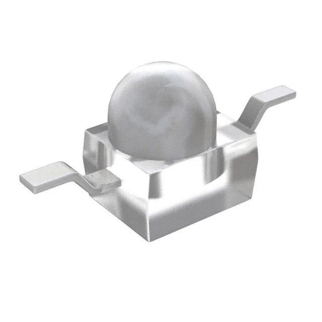
Vishay Semiconductor Opto Division VLDY1535R-08
Part No.:
VLDY1535R-08
Manufacturer:
Vishay Semiconductor Opto Division
Category:
LED Indication - Discrete
Package:
2-SMD, Z-Bend
Datasheet:
AetrixVLDY1535R-08.pdf
Description:
LED YELLOW CLEAR 2SMD BOTTOM ENT
Quantity:
Payment:
Payment
Shipping:
Shipping

Inventory:7,321

Please send an inquiry. Send us your inquiry, and we will respond immediately.

Part Number
Quantity*
Price
Name*
Company
Email*
Comments

Product details

Overview

VLDY1535R-08 from Vishay Semiconductors is a yellow surface-mount LED with dome lens, designed for high-brightness indicator and backlighting applications. It delivers 4500–14 000 mcd luminous intensity at 50 mA, features AlInGaP-on-Si chip technology, ±22° viewing angle, and operates with 1.9–2.7 V forward voltage.

For engineers reviewing the VLDY1535R-08 datasheet, VLDY1535R-08 pinout, VLDY1535R-08 application, or VLDY1535R-08 equivalent, this page provides verified optical/electrical specs, thermal derating curves, JEDEC level 2a moisture sensitivity data, gullwing/reverse gullwing package dimensions, and real-world use context for traffic signage, industrial indicators, and LCD backlighting.

Technical Context

The VLDY1535R-08 uses AlInGaP-on-Si die architecture to achieve high luminous intensity (up to 14 000 mcd) and stable yellow emission (583–595 nm dominant wavelength) under DC forward current up to 70 mA. Its ±22° half-intensity angle and 2.3 × 2.3 × 2.6 mm SMD dome lens package enable directional light output with minimal beam spread.

Thermal resistance is 325 K/W junction-to-ambient when mounted on ≥16 mm² PCB copper pad, supporting operation from –40 °C to +100 °C ambient. ESD withstand voltage reaches 2 kV (HBM, JESD22-A114-B), and it complies with J-STD-020 reflow profiles including peak temperature ≤260 °C for ≤100 s.

Key Specifications

Parameter Value and Actual Design Meaning
Luminous intensity 4500–14 000 mcd @ 50 mA - enables high-visibility indication in ambient lighting up to 10 klux
Dominant wavelength 583–595 nm - precise yellow chromaticity compliant with CIE 1931 color space for signaling
Forward voltage 1.9–2.7 V @ 50 mA - compatible with 3.3 V and 5 V logic-level drive without external regulation
Viewing angle ±22° half-intensity - focused beam ideal for discrete status indication and symbol illumination
Max DC forward current 70 mA @ Tamb ≤ 60 °C - supports sustained brightness in compact thermal environments
Junction temperature 125 °C max - defines upper thermal limit for reliability-critical automotive/industrial mounting
ESD rating 2 kV HBM (JESD22-A114-B) - ensures robustness during automated SMT handling and board assembly

Pinout & Package

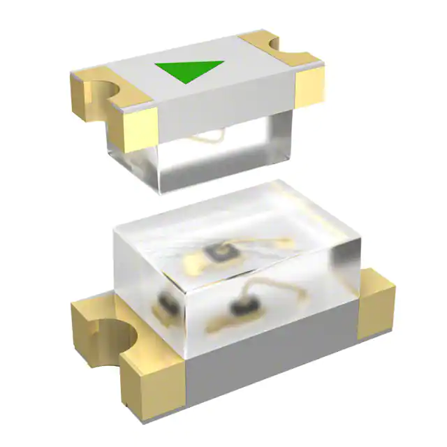
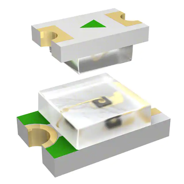
Package: SMD dome lens, 2.3 × 2.3 × 2.6 mm footprint, available in gullwing (anode/cathode on same side) and reverse gullwing (anode/cathode on opposite sides) configurations per drawing 6.544-5408.01-4 and 6.544-5409.01-4. Exposed copper thermal pad enhances heat dissipation.

Pin/Terminal Circuit Role Design Meaning
Anode Positive DC input Accepts forward current up to 70 mA; requires series resistor or constant-current driver for bias control
Cathode Ground reference Connected to PCB ground plane; serves as primary thermal path via exposed copper pad

Key Features

Feature Design Value
AlInGaP-on-Si chip technology Delivers high luminous flux (1.2 mlm/mcd ratio) and stable yellow output across temperature range
JEDEC level 2a moisture sensitivity Enables standard SMT reflow without baking if used within 672 hours of dry-pack opening
Luminous intensity binning (FA group) Ensures consistent brightness across reels-no mixing of intensity groups per reel
Wavelength binning (groups 5–6) Guarantees tight 589–595 nm dominant wavelength control for color-critical signage
Reflow-compatible termination finish Lead-free matte tin plating supports J-STD-020 profile with peak temp ≤260 °C and ramp rates ≤3 °C/s

Applications

Traffic Signal Indicators Industrial Control Panel Status

Use Scenario: Red/yellow/green signal modules in roadside cabinets requiring daylight-visible status feedback.

IC Role / Device Role / Timing Role: Discrete visual indicator emitting standardized yellow chromaticity for stop-wait phases.

Use Value: 14 000 mcd intensity and ±22° beam ensure legibility at >10 m distance under direct sunlight exposure.

Use Scenario: Power-on, fault, or mode indicators on DIN-rail mounted PLC I/O modules.

IC Role / Device Role / Timing Role: Standalone status emitter with no timing or logic function-driven directly by microcontroller GPIO.

Use Value: 70 mA max current and -40 °C to +100 °C operating range support continuous operation in unventilated enclosures.

LCD Keypad Backlighting Automotive Interior Symbols

Use Scenario: Edge-lit alphanumeric keys on consumer audio/video remote controls.

IC Role / Device Role / Timing Role: Low-profile surface-mount light source positioned beneath translucent keycaps.

Use Value: 2.3 mm × 2.3 mm footprint and dome lens provide uniform illumination without hotspots or shadowing.

Use Scenario: Illuminated HVAC or gear selector symbols in passenger vehicle dashboards.

IC Role / Device Role / Timing Role: Ambient-light-adapted indicator driven by PWM dimming circuitry.

Use Value: 2 kV ESD rating and 125 °C junction temperature withstand automotive ESD events and under-hood thermal cycling.

Equivalent & Alternatives

The following parts are listed as comparable options for similar yellow LED indicator applications.

Alternative Part Technical Difference Application Difference Selection Advice
VLDY1535G-08 Same package and optics, but green-emitting (525 nm typ.) with identical 4500–14 000 mcd intensity range Used where color coding requires green instead of yellow (e.g., "ready" vs. "warning" states) Select VLDY1535G-08 only when green chromaticity is required; otherwise VLDY1535R-08 maintains yellow compliance.
VLDR1535R-08 Red-emitting (624 nm typ.), higher intensity (3550–11 200 mcd), same 2.3 × 2.3 mm package and ±22° viewing angle Preferred for red-status applications like power-off or alarm indicators where yellow is not color-coded Choose VLDR1535R-08 for red signaling; VLDY1535R-08 is mandatory where yellow is specified per ISO/SAE standards.

Compared with VLDY1535G-08 and VLDR1535R-08, the VLDY1535R-08 uniquely satisfies yellow-specific signaling requirements-its 589 nm typical dominant wavelength and FA intensity binning ensure regulatory-compliant chromaticity and brightness consistency where green or red alternatives would fail color validation.

Availability

VLDY1535R-08 is available at Aetrix Electronics and suitable for traffic signal modules, industrial HMI panels, and automotive interior symbols requiring stable component supply, consistent luminous intensity binning, and JEDEC level 2a moisture-safe reflow compatibility.

Supply support for VLDY1535R-08 includes scheduled delivery planning, volume procurement assistance, BOM continuity management, traceable sourcing, and lifecycle availability coordination for OEM customers, industrial embedded developers, connected-device designers, and electronics production programs.

Manufacturer

Vishay Semiconductors designs and manufactures discrete semiconductors and optoelectronics with emphasis on reliability, precision, and application-specific performance across automotive, industrial, and computing markets.

The VLDY1535R-08 belongs to Vishay's power LED product group, engineered for high-brightness surface-mount indicator and backlighting applications demanding stable chromaticity, wide temperature operation, and robust SMT manufacturability.

FAQ

What is the maximum allowable forward current for VLDY1535R-08 at 85 °C ambient temperature?

The VLDY1535R-08 supports 70 mA DC forward current only when ambient temperature is ≤60 °C. At 85 °C, derating applies: Fig. 1 shows maximum permissible current drops to ~45 mA. Exceeding this risks accelerated lumen depreciation and junction overheating beyond the 125 °C limit. Always consult the thermal resistance (325 K/W) and actual board copper area when designing for elevated temperatures. The VLDY1535R-08 must be operated within these limits to maintain rated lifetime.

Does VLDY1535R-08 have a built-in current-limiting resistor?

No, the VLDY1535R-08 is a bare LED die in an SMD package with no integrated current-limiting resistor. It requires an external series resistor or constant-current driver to regulate forward current to 50 mA (typical operating point) or up to 70 mA (absolute max at Tamb ≤ 60 °C). The VLDY1535R-08 forward voltage range of 1.9–2.7 V at 50 mA means resistor value must be calculated per actual VF measurement and supply voltage. Failure to include external current control will cause thermal runaway and premature failure of the VLDY1535R-08.

Is VLDY1535R-08 suitable for outdoor traffic signal applications?

Yes, the VLDY1535R-08 is explicitly designed for traffic signals and signs per its Applications section. Its 14 000 mcd max luminous intensity at 50 mA, ±22° viewing angle, and –40 °C to +100 °C operating range meet outdoor visibility and environmental durability requirements. The dome lens provides UV-stable optical coupling, and the AlInGaP-on-Si chip ensures low wavelength shift over temperature (Fig. 9 shows <10 nm drift from –40 °C to +100 °C). For full compliance, pair the VLDY1535R-08 with appropriate thermal management and IP-rated housing.

What does the "R" suffix in VLDY1535R-08 indicate?

The "R" in VLDY1535R-08 denotes reverse gullwing lead configuration-cathode and anode leads extend from opposite sides of the 2.3 × 2.3 mm body, enabling orthogonal PCB routing and improved mechanical stability during reflow. This contrasts with the "G" suffix (e.g., VLDY1535G-08), which indicates standard gullwing leads on the same side. Both variants share identical optical, electrical, and thermal specs; the "R" solely defines mechanical mounting orientation. The VLDY1535R-08 drawing number is 6.544-5409.01-4.

How is luminous intensity binned for VLDY1535R-08, and what does "FA" mean?

VLDY1535R-08 is binned into luminous intensity groups per Table "LUMINOUS INTENSITY CLASSIFICATION": "FA" corresponds to 7100–9000 mcd at 50 mA. Each reel ships only one intensity group-no mixing-and FA is one of six standard bins (CA through FA). This ensures brightness uniformity across production lots. The VLDY1535R-08 datasheet specifies that FA-group devices deliver predictable visual output in multi-LED arrays, critical for consistent panel appearance in HMI and signage. Binning tolerance is ±15 % per test condition.

VLDY1535R-08 Specifications

Product attributes
Attribute value
Manufacturer:
Vishay Semiconductor Opto Division
Series:
VLD.1535
Package/Case:
2-SMD, Z-Bend
Packaging:
Tape & Reel (TR)
Product Status:
Active
Color:
Yellow
Configuration:
Independent
Lens Color:
Colorless
Lens Transparency:
Clear
Millicandela Rating:
8000mcd
Lens Style:
Round with Domed Top
Lens Size:
1.80mm Dia
Voltage - Forward (Vf) (Typ):
2.3V
Current - Test:
50mA
Viewing Angle:
44°
Mounting Type:
Surface Mount, Bottom Entry
Wavelength - Dominant:
589nm
Wavelength - Peak:
591nm
Features:
-
Grade:
-
Qualification:
-
Supplier Device Package:
2-SMD
Size / Dimension:
2.30mm L x 2.30mm W

VLDY1535R-08 FAQ

1.How can I place an order for VLDY1535R-08 through Aetrix?

Please submit a Request for Quotation (RFQ) for VLDY1535R-08 on Aetrix. Our sales agent will provide a competitive quotation and guide you through the order confirmation once you accept the terms.

2.Are the price and stock information for VLDY1535R-08 reliable?

The price and inventory of VLDY1535R-08 are updated periodically and may fluctuate due to market conditions. Stock and pricing data are typically refreshed every 24 hours. Quotation validity for VLDY1535R-08 is usually 5 days.

3.What payment methods are accepted for VLDY1535R-08?

We accept Wire Transfer, PayPal, Credit Card, Western Union, MoneyGram, and Escrow for VLDY1535R-08 transactions.

Note: Certain payment methods may incur a processing fee.

4.How is shipping managed for VLDY1535R-08?

VLDY1535R-08 orders can be shipped via leading logistics carriers, including DHL, UPS, FedEx, TNT, or Registered Mail.

Once your VLDY1535R-08 order is processed, you will receive an email with the shipment details and tracking number.

Note: Tracking information may take up to 24 hours to appear. Express delivery typically takes 3–5 business days.

5.How can I obtain technical support or documentation for VLDY1535R-08?

For technical support, including VLDY1535R-08 datasheets, pinout diagrams, or application guidance, please contact our engineering support team. They can provide detailed documentation and assistance for your VLDY1535R-08 requirements.

6.How does Aetrix verify that VLDY1535R-08 is sourced from the original manufacturer or authorized distributors?

All VLDY1535R-08 products on Aetrix are procured from qualified distributors and authorized channels. Our dedicated quality assurance team conducts strict verification, including traceability checks and, if necessary, third-party testing. This ensures that VLDY1535R-08 meets industry standards.

7.What is the process for return or replacement of VLDY1535R-08?

All VLDY1535R-08 units undergo pre-shipment inspection (PSI). If there is an issue with VLDY1535R-08, returns or replacements are accepted under the following conditions:

1.Quantity discrepancies, incorrect items, or visible external defects (such as breakage or corrosion), acknowledged by Aetrix.

2.The issue is reported within 90 days of delivery.

3.The VLDY1535R-08 part is unused and in its original packaging.

Return procedure for VLDY1535R-08:

1.Submit a request within 90 days.

2.Obtain a Return Material Authorization (RMA) from Aetrix.

VLDY1535R-08 Tags

  • VLDY1535R-08
  • VLDY1535R-08 PDF
  • VLDY1535R-08 Datasheet
  • VLDY1535R-08 Specifications
  • VLDY1535R-08 Images
  • Vishay Semiconductor Opto Division
  • Vishay Semiconductor Opto Division VLDY1535R-08
  • Buy VLDY1535R-08
  • VLDY1535R-08 Price
  • VLDY1535R-08 Distributor
  • VLDY1535R-08 Supplier
  • VLDY1535R-08 Wholesale
Related Products
LTST-C281KRKT
LTST-C281KRKT

Lite-On Inc.

150060GS75000
150060GS75000

Würth Elektronik

150060VS75000
150060VS75000

Würth Elektronik

150060AS75000
150060AS75000

Würth Elektronik

150060YS75000
150060YS75000

Würth Elektronik

150060SS75000
150060SS75000

Würth Elektronik

150060BS75000
150060BS75000

Würth Elektronik

151031VS06000
151031VS06000

Würth Elektronik

151033RS03000
151033RS03000

Würth Elektronik

150080BS75000
150080BS75000

Würth Elektronik

150080GS75000
150080GS75000

Würth Elektronik

150141GS73100
150141GS73100

Würth Elektronik

Tech Hub

Search

Search

PRODUCT

PRODUCT

PHONE

PHONE

USER

USER