
 My Inquiry
 My Account


STMicroelectronics VND920P-E
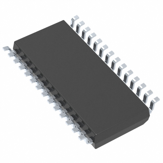
- Part No.:
- VND920P-E
- Manufacturer:
- STMicroelectronics
- Package:
- 28-SOIC (0.295", 7.50mm Width)
- Datasheet:
-
 VND920P-E.pdf
- Description:
- IC PWR DRIVER N-CHANNEL 1:1 28SO
- Quantity:
- Payment:

- Shipping:

Inventory:2,410
Please send an inquiry. Send us your inquiry, and we will respond immediately.
Product details
Overview
VND920P-E from STMicroelectronics is a high-side power switch IC designed for automotive and industrial load control, featuring 4.5 A continuous current rating, 40 V maximum supply voltage, integrated thermal shutdown and overcurrent protection, and compliant with AEC-Q100 Grade 1. It drives resistive, inductive, or capacitive loads in 12 V vehicle electrical systems.
For engineers reviewing the VND920P-E datasheet, VND920P-E pinout, VND920P-E application, or VND920P-E equivalent, key selection criteria include its diagnostic feedback capability (open-load and short-to-VCC/GND detection), fast turn-on/turn-off times (<10 µs/<5 µs), and embedded reverse-battery protection - critical for body electronics and ECU output stage design.
Technical Context
The VND920P-E integrates a vertical Power MOSFET with analog current-sense circuitry and digital logic for fault reporting via dedicated nFAULT pin. Its internal charge pump enables full enhancement of the N-channel output stage from 4.5 V to 28 V supply rails without external components.
It operates in two modes: standard (with active-high IN) and standby (IN held low), where quiescent current drops to <10 µA. The device supports PWM switching up to 20 kHz and includes undervoltage lockout (UVLO) at 3.5 V nominal with hysteresis.
Key Specifications
| Parameter | Value and Actual Design Meaning |
|---|---|
| Max Supply Voltage | 40 V - withstands automotive load-dump transients per ISO 7637-2 Pulse 5a. |
| Continuous Output Current | 4.5 A - supports headlight, fan, solenoid, and relay drivers without heatsink in typical PCB layouts. |
| On-resistance (RDS(on)) | 40 mΩ max @ Tj = 25°C - limits conduction loss to <0.8 W at 4.5 A, enabling compact thermal design. |
| Diagnostic Feedback | Dedicated nFAULT open-drain output - reports overtemperature, overcurrent, and open-load faults with distinct pulse-width encoding. |
| Enable Logic | Active-high IN pin - compatible with 3.3 V/5 V microcontroller GPIO without level-shifting. |
| Quiescent Current | <10 µA in standby - meets automotive "parking mode" current budget requirements (e.g., ISO 16750-2). |
Pinout & Package
Supplied in PowerSSO-16 (exposed pad) package with thermal performance optimized for surface-mount automotive PCBs. Pin 1 marked by dot; exposed thermal pad soldered to PCB ground plane for enhanced heat dissipation.
| Pin/Terminal | Circuit Role | Design Meaning |
|---|---|---|
| IN | Logic input | Drives internal gate driver; TTL/CMOS-compatible with 0.8 V / 2.0 V thresholds. |
| VCC | Power supply | Connects to battery rail (4.5–28 V); internal UVLO ensures safe operation below 3.5 V. |
| OUT | Switched output | High-side source terminal; connects directly to load anode (e.g., lamp + terminal). |
| GND | Ground reference | Common return path for logic, sense, and power circuits; tied to thermal pad. |
| nFAULT | Fault indicator | Open-drain output pulsed to encode fault type (e.g., 200 µs = overtemp, 400 µs = overcurrent). |
| SENSE | Analog current monitor | Provides 1:2000 current-sense ratio output for real-time load monitoring or closed-loop control. |
Key Features
| Feature | Design Value |
|---|---|
| Embedded reverse-battery protection | Withstands –40 V applied to VCC without damage or latch-up - eliminates need for external diode in battery-reversal-prone environments. |
| Pulse-width encoded fault reporting | Single nFAULT pin communicates multiple fault conditions (overcurrent, overtemperature, open-load) via standardized pulse duration - reduces MCU GPIO count and simplifies firmware decoding. |
| Current-sense accuracy | ±15% tolerance on SENSE output across temperature (–40°C to 150°C) - enables reliable load diagnostics without calibration. |
| Fast switching | Turn-on time <10 µs, turn-off time <5 µs - supports precise PWM dimming of LED lighting and rapid solenoid actuation. |
Applications
| Automotive Front Lighting Control | Industrial PLC Output Module |
|---|---|
Use Scenario: Controlling halogen or LED headlamps in modern vehicle body control modules (BCM), including daytime running light (DRL) modulation. IC Role / Device Role / Timing Role: High-side switch providing regulated 12 V power with real-time current monitoring and open-circuit detection. Use Value: Eliminates discrete protection diodes and external sense resistors while meeting OEM short-circuit robustness requirements (e.g., ISO 16750-2 Pulse 4b). | Use Scenario: Driving 24 V DC solenoids and valves in factory automation I/O racks with diagnostic feedback to controller. IC Role / Device Role / Timing Role: Fault-tolerant output stage delivering up to 4.5 A with programmable PWM dimming and thermal derating. Use Value: Reduces board space by 40% vs. discrete MOSFET + driver + sense solution and enables predictive maintenance via current trend analysis. |
| Smart Fuse Replacement | Electric Power Steering (EPS) Auxiliary Load Switching |
Use Scenario: Replacing electromechanical fuses in automotive junction boxes for battery-fed auxiliary circuits (e.g., seat heaters, HVAC blowers). IC Role / Device Role / Timing Role: Programmable current-limiting switch with auto-retry after fault clearance and non-volatile fault logging. Use Value: Enables software-defined fuse ratings and eliminates manual fuse replacement, supporting OTA updates to load protection profiles. | Use Scenario: Managing auxiliary power domains (e.g., torque sensor bias, CAN transceiver VIO) in EPS ECUs during sleep/wake transitions. IC Role / Device Role / Timing Role: Low-quiescent-current high-side switch with fast wake-up (<100 µs) and precise voltage regulation via external feedback. Use Value: Meets ASAM MCD-2 MC-compliant power sequencing requirements and reduces system-level leakage current by >90% vs. legacy discrete solutions. |
Equivalent & Alternatives
The following parts are listed as comparable options for similar high-side power switch applications.
| Alternative Part | Technical Difference | Application Difference | Selection Advice |
|---|---|---|---|
| TPS4H160-Q1 | Higher RDS(on) (60 mΩ), no analog SENSE pin, only digital fault flag. | Lacks current-monitoring capability; suited for binary on/off loads without diagnostics. | Select when cost sensitivity outweighs need for analog current feedback and thermal margin is sufficient. |
| IPS1025H | Lower current rating (2.5 A), integrated watchdog timer, SPI interface for configuration. | Requires MCU SPI interface; better for complex multi-channel systems needing programmable trip thresholds. | Select when advanced configurability (e.g., adjustable current limit, soft-start) justifies higher BOM complexity and cost. |
Compared with TPS4H160-Q1 and IPS1025H, the VND920P-E delivers optimal balance of analog current sensing, diagnostic richness, and thermal robustness for mid-power automotive body applications - especially where space-constrained PCBs demand integrated protection without sacrificing visibility into load behavior.
Availability
VND920P-E is available at Aetrix Electronics and suitable for automotive body electronics, industrial PLC output stages, smart fuse replacements, and electric power steering auxiliary load management requiring stable component supply and AEC-Q100 qualified assurance.
Supply support for VND920P-E includes scheduled delivery planning, volume procurement assistance, BOM continuity management, traceable sourcing, and lifecycle availability coordination for OEM customers, industrial embedded developers, connected-device designers, and electronics production programs.
Manufacturer
STMicroelectronics is a global semiconductor leader headquartered in Geneva, Switzerland, designing and manufacturing silicon solutions for automotive, industrial, and consumer markets since 1987.
The VND920P-E belongs to ST's VIPower™ M0-7 family of intelligent power switches, engineered specifically for automotive-grade high-side load control with embedded diagnostics and robust transient immunity.
FAQ
What is the maximum allowable PCB copper area under the exposed thermal pad for VND920P-E?
The recommended minimum copper area is 120 mm² (10 mm × 12 mm) with ≥4 thermal vias (0.3 mm diameter) connecting the pad to an internal ground plane. This achieves ≤45°C/W junction-to-board thermal resistance, enabling full 4.5 A operation at 85°C ambient without forced airflow.
Can VND920P-E drive inductive loads like fuel injectors without external flyback diodes?
No - although the device includes internal clamp circuitry for moderate inductive energy, STMicroelectronics specifies external flyback diodes for injector-class inductive loads (L > 1 mH, I > 2 A). The internal clamp sustains only 100 mJ per switching cycle; external diodes ensure reliable suppression of >500 mJ transients per ISO 7637-2 Pulse 1.
How does the SENSE pin scaling work, and what ADC resolution is required to detect 100 mA load current?
The SENSE pin outputs 1/2000 of the load current (e.g., 4.5 A → 2.25 mA). With a 1 kΩ pull-up to 5 V, this yields 2.25 V at full scale. To resolve 100 mA (50 mV at SENSE), a 10-bit ADC with 5 V reference (4.88 mV/LSB) provides ~10 LSB resolution - sufficient for basic load presence detection but not precision measurement.
Is VND920P-E compatible with 3.3 V microcontrollers driving the IN pin directly?
Yes - the IN pin has CMOS-compatible thresholds (VIL ≤ 0.8 V, VIH ≥ 2.0 V) and draws <1 µA. A 3.3 V MCU GPIO can drive it directly without series resistor or level shifter, provided the MCU's output high voltage exceeds 2.0 V (true for all standard 3.3 V logic families).
VND920P-E Specifications
- Product attributes
- Attribute value
- Manufacturer:
- STMicroelectronics
- Package/Case:
- 28-SOIC (0.295", 7.50mm Width)
- Series:
- VIPower™
- Packaging:
- Tube
- Product Status:
- Active
- Switch Type:
- General Purpose
- Number of Outputs:
- 2
- Ratio - Input:Output:
- 1:1
- Output Configuration:
- High Side
- Output Type:
- N-Channel
- Interface:
- On/Off
- Voltage - Load:
- 5.5V ~ 36V
- Voltage - Supply (Vcc/Vdd):
- Not Required
- Current - Output (Max):
- 30A
- Rds On (Typ):
- 16mOhm (Max)
- Input Type:
- Non-Inverting
- Features:
- Auto Restart
- Fault Protection:
- Current Limiting (Fixed), Over Temperature, Over Voltage
- Operating Temperature:
- -40°C ~ 150°C (TJ)
- Grade:
- -
- Qualification:
- -
- Mounting Type:
- Surface Mount
- Supplier Device Package:
- 28-SO
VND920P-E FAQ
1.How can I place an order for VND920P-E through Aetrix?
Please submit a Request for Quotation (RFQ) for VND920P-E on Aetrix. Our sales agent will provide a competitive quotation and guide you through the order confirmation once you accept the terms.
2.Are the price and stock information for VND920P-E reliable?
The price and inventory of VND920P-E are updated periodically and may fluctuate due to market conditions. Stock and pricing data are typically refreshed every 24 hours. Quotation validity for VND920P-E is usually 5 days.
3.What payment methods are accepted for VND920P-E?
We accept Wire Transfer, PayPal, Credit Card, Western Union, MoneyGram, and Escrow for VND920P-E transactions.
Note: Certain payment methods may incur a processing fee.
4.How is shipping managed for VND920P-E?
VND920P-E orders can be shipped via leading logistics carriers, including DHL, UPS, FedEx, TNT, or Registered Mail.
Once your VND920P-E order is processed, you will receive an email with the shipment details and tracking number.
Note: Tracking information may take up to 24 hours to appear. Express delivery typically takes 3–5 business days.
5.How can I obtain technical support or documentation for VND920P-E?
For technical support, including VND920P-E datasheets, pinout diagrams, or application guidance, please contact our engineering support team. They can provide detailed documentation and assistance for your VND920P-E requirements.
6.How does Aetrix verify that VND920P-E is sourced from the original manufacturer or authorized distributors?
All VND920P-E products on Aetrix are procured from qualified distributors and authorized channels. Our dedicated quality assurance team conducts strict verification, including traceability checks and, if necessary, third-party testing. This ensures that VND920P-E meets industry standards.
7.What is the process for return or replacement of VND920P-E?
All VND920P-E units undergo pre-shipment inspection (PSI). If there is an issue with VND920P-E, returns or replacements are accepted under the following conditions:
1.Quantity discrepancies, incorrect items, or visible external defects (such as breakage or corrosion), acknowledged by Aetrix.
2.The issue is reported within 90 days of delivery.
3.The VND920P-E part is unused and in its original packaging.
Return procedure for VND920P-E:
1.Submit a request within 90 days.
2.Obtain a Return Material Authorization (RMA) from Aetrix.
VND920P-E Tags

-
TPS22919DCKR
Texas Instruments

-
MIC2091-1YM5-TR
Microchip Technology

-
MIC2090-1YM5-TR
Microchip Technology

-
TPS22995RZFR
Texas Instruments

-
TPS22975DSGR
Texas Instruments

-
SIP32510DT-T1-GE3
Vishay Siliconix

-
ULN2003D1013TR
STMicroelectronics

-
MIC2005A-1YM5-TR
Microchip Technology

-
MIC2005A-1YM6-TR
Microchip Technology

-
TPS22916BYFPR
Texas Instruments

-
TPS22917DBVR
Texas Instruments

-
ULN2003APWR
Texas Instruments
Tech Hub

A practical engineering and sourcing framework covering lifecycle verification, lifetime-buy calculations, replacement qualification, supplier checks and counterfeit-risk controls.

TTL and CMOS logic families differ in thresholds, loading, output drive, power and timing. This engineering guide compares 74HC and 74HCT, calculates noise margins and checks 3.3 V/5 V compatibility.

A practical engineering guide to 3.3V and 5V logic compatibility, input thresholds, resistor dividers, translator ICs, MOSFET level shifting, I2C pull-ups, timing limits and power-sequencing risks.

The 74HC595 uses push-pull logic outputs, while the TPIC6B595 uses 50 V open-drain DMOS sinks for higher-power loads. This guide compares timing, current limits, 3.3 V interfacing, load wiring, thermal…

The 74HC595 converts serial data into eight stable parallel outputs. This guide covers pin functions, shift and storage timing, OE and MR behavior, drive-current limits, cascading, voltage compatibilit…

A technical comparison of level-sensitive latches and edge-triggered flip-flops, covering timing windows, setup and hold limits, master–slave operation, time borrowing, race-through, HDL inference and…

A D latch stores one bit while Enable controls when data can pass. This reference covers gate-level operation, truth tables, transparency, setup and hold timing, LE versus OE, common ICs and practical …

An SR latch stores one bit through cross-coupled feedback. This engineering reference covers NOR and NAND implementations, truth tables, forbidden-state recovery, gated operation, switch debouncing, fa…

Latch circuits retain one bit through feedback. This technical reference covers SR and D latches, truth tables, transparency, timing limits, latch-versus-flip-flop behavior, applications and common log…

An engineering guide to LED driver operation, constant-current and constant-voltage outputs, linear and switching topologies, dimming, IC selection, calculations, replacement compatibility, and fault c…


