
 My Inquiry
 My Account


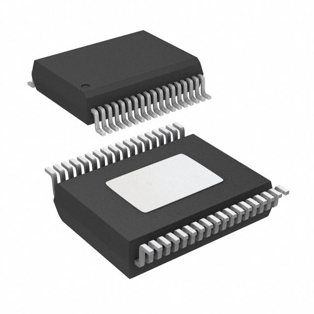
STMicroelectronics VNQ6040S-E
- Part No.:
- VNQ6040S-E
- Manufacturer:
- STMicroelectronics
- Package:
- 36-PowerBFSOP (0.295", 7.50mm Width)
- Datasheet:
-
 VNQ6040S-E.pdf
- Description:
- IC PWR DRVR N-CHAN 1:1 PWRSSO36
- Quantity:
- Payment:

- Shipping:

Inventory:3,640
Please send an inquiry. Send us your inquiry, and we will respond immediately.
Product details
Overview
VNQ6040S-E from STMicroelectronics is a quad-channel high-side driver IC built on VIPower® technology, designed for driving resistive or inductive loads (e.g., automotive lamps, solenoids, valves) directly connected to ground. It delivers 4 A continuous output current per channel, supports 16-bit ST-SPI interface with real-time diagnostics, and features programmable BULB/LED modes with integrated PWM and phase-shift generation.
For engineers reviewing the VNQ6040S-E datasheet, VNQ6040S-E pinout, VNQ6040S-E application, or VNQ6040S-E equivalent, key selection considerations include its 4-channel independent control, multiplexed analog current sense per channel, fail-safe limp-home mode during digital supply loss, and robust protection against overtemperature, open-load (ON/OFF-state), short-to-VCC/GND, load dump, and reverse battery - all without external components.
Technical Context
The device operates in five distinct modes - Normal, Standby, Sleep 1/2, Fail-Safe (limp-home), and Battery Undervoltage - each governed by internal state machine logic and configurable via SPI registers. Its diagnostic architecture enables synchronous sampling of load current via CS_SYNC and multiplexed CURRENT-SENSE pin, with real-time reporting of open-load (both states), overtemperature, overload, and communication errors through dedicated status registers (e.g., OLFLTR, OTFLTR, OVLFLTR).
Protection is implemented at silicon level: power limitation dynamically caps dissipation before thermal shutdown; overtemperature response is user-selectable (latched-off or auto-restart); reverse-battery immunity is achieved via self-turn-on of power outputs; and undervoltage shutdown activates below 4.5 V on VDD while maintaining VCC operation down to 5.5 V.
Key Specifications
| Parameter | Value and Actual Design Meaning |
|---|---|
| Channels | 4 independent high-side outputs with individual SPI-controlled enable and diagnostics |
| Continuous Output Current | 4 A per channel (TA ≤ 85 °C, RθJA = 25 °C/W) |
| Supply Voltage Range (VCC) | 5.5 V to 28 V - supports automotive battery transients including load dump (ISO 7637-2 Pulse 5a) |
| SPI Interface | 16-bit ST-SPI (mode 0, CPOL=0, CPHA=0) with 10 MHz max clock, supporting read/write/status-clear operations |
| Current Sense Accuracy | ±10% full-scale error across 8–18 V VCC range, multiplexed to single CURRENT-SENSE pin |
| Thermal Shutdown | Configurable latched-off or auto-restart at TJ ≥ 175 °C ± 10 °C |
| Standby Current | ≤ 10 µA typical - enables low-power vehicle-off monitoring |
Pinout & Package
Package: PowerSSO-36 (exposed die pad, thermally enhanced SO-36 variant, RoHS-compliant ECOPACK®).
| Pin/Terminal | Circuit Role | Design Meaning |
|---|---|---|
| VCC | Main power supply input | Accepts 5.5–28 V; protected against load dump (up to 60 V/100 ms) and reverse battery |
| VDD | Digital supply input | 3.3 V or 5 V logic supply; undervoltage lockout at ~4.5 V triggers fail-safe mode |
| OUT0–OUT3 | High-side power outputs | Each drives grounded loads; rated 4 A continuous, 10 A peak (100 ms) |
| IN0–IN3 | Limp-home direct control inputs | Hardware override pins active only in fail-safe mode; TTL/CMOS compatible |
| CSN | SPI chip select | Active-low; initiates SPI frame; timeout monitoring enables automatic fail-safe entry |
| SDI/SDO/SCK | SPI data in/out and clock | Full-duplex 16-bit interface; SDO supports daisy-chain configuration |
| CURRENT-SENSE | Analog current feedback output | Multiplexed channel current sense (0.5 V/A nominal); synchronized by CS_SYNC |
| CS_SYNC | Current sense synchronization | Open-drain signal indicating when current sense is valid for sampling |
| GND | Power and analog ground | Single ground plane; exposed pad must be soldered for thermal performance |
Key Features
| Feature | Design Value |
|---|---|
| Programmable BULB/LED mode | Optimized switching profiles and current regulation for incandescent lamp inrush suppression or constant-current LED drive |
| Integrated PWM & phase shift | On-chip 160 Hz fallback PWM generator with per-channel duty cycle (0–100%) and phase offset (0–360°) control via SPI registers |
| Advanced limp-home functionality | Automatic transition to hardware-controlled INx pins upon VDD loss, memory reset, or CSN timeout - ensures critical actuation continuity |
| Multiplexed proportional current sense | Single analog pin delivers scaled load current (0.5 V/A) for all 4 channels with <1 µs propagation delay and synchronous sampling window |
| Reverse-battery protection | No external diodes required; power outputs self-turn-on to clamp negative VCC transients down to –18 V |
Applications
| Automotive Front Lighting Control | Industrial Solenoid Sequencing |
|---|---|
Use Scenario: Driving halogen headlamp filaments with inrush current limiting and filament break detection. IC Role / Device Role / Timing Role: High-side switch with BULB-mode PWM ramp-up, open-load ON-state detection, and real-time current monitoring via SPI. Use Value: Eliminates need for external current-sense shunts and discrete protection ICs while enabling diagnostics compliant with UNECE R128. | Use Scenario: Controlling pneumatic valve banks in factory automation with precise timing and fault logging. IC Role / Device Role / Timing Role: Quad-channel high-side driver with programmable phase-shifted PWM for staggered actuation and thermal load balancing. Use Value: Reduces peak system current by >30% versus simultaneous switching, avoiding PSU oversizing and thermal derating. |
| Commercial Vehicle Brake Light Management | Off-Highway Equipment Lamp Monitoring |
Use Scenario: Managing stop/tail/turn lamps in heavy-duty trucks subject to severe voltage transients and EMI. IC Role / Device Role / Timing Role: Fault-tolerant high-side driver with load-dump protection, reverse-battery immunity, and synchronous open-load OFF-state detection. Use Value: Maintains lamp status visibility during battery disconnection events and eliminates false open-circuit alarms during vibration-induced intermittent faults. | Use Scenario: Monitoring LED work lights on construction machinery where ambient temperature exceeds 105 °C. IC Role / Device Role / Timing Role: Thermally robust high-side driver with auto-restart thermal shutdown and case overtemperature warning via SPI status register (OTFLTR). Use Value: Enables predictive maintenance alerts before thermal shutdown occurs, reducing unplanned downtime in harsh environments. |
Equivalent & Alternatives
The following parts are listed as comparable options for similar high-side driver applications.
| Alternative Part | Technical Difference | Application Difference | Selection Advice |
|---|---|---|---|
| TPS4H160-Q1 | 4-channel, 2.8 A/channel, 40 V abs max, SPI+PWM, no BULB-mode optimization | Lacks dedicated lamp inrush management; requires external current sense for diagnostics | Preferred for lower-current 12 V systems needing AEC-Q100 Grade 0 qualification and smaller footprint |
| BD3903FV-M | Quad high-side, 3 A/channel, I²C interface, no integrated PWM generator or phase shift | Supports only basic ON/OFF control; no synchronous current sense or limp-home mode | Suitable for cost-sensitive non-automotive industrial use where SPI diagnostics and fail-safe continuity are not required |
Compared with TPS4H160-Q1 and BD3903FV-M, the VNQ6040S-E uniquely integrates lamp-specific BULB-mode timing, per-channel phase-shifted PWM, and hardware-based limp-home override - making it the only option supporting full diagnostic continuity and thermal resilience in demanding automotive lighting ECU designs.
Availability
VNQ6040S-E is available at Aetrix Electronics and suitable for automotive lighting control, industrial solenoid sequencing, commercial vehicle brake light management, and off-highway equipment lamp monitoring requiring stable component supply across extended temperature and transient-voltage conditions.
Supply support for VNQ6040S-E includes scheduled delivery planning, volume procurement assistance, BOM continuity management, traceable sourcing, and lifecycle availability coordination for OEM customers, industrial embedded developers, connected-device designers, and electronics production programs.
Manufacturer
STMicroelectronics is a global semiconductor leader headquartered in Geneva, Switzerland, specializing in automotive, industrial, and power management ICs with vertical manufacturing and AEC-Q100-qualified product lines.
The VNQ6040S-E belongs to ST's VIPower® M0-7 family of intelligent power switches, engineered specifically for automotive body electronics applications demanding high reliability, integrated diagnostics, and fail-operational behavior under electrical stress.
FAQ
What is the maximum safe operating junction temperature for VNQ6040S-E?
The VNQ6040S-E has a thermal shutdown threshold of 175 °C ± 10 °C, with automatic restart enabled by default unless configured otherwise via the Automatic Shutdown Control Register (ASDTCR). The device remains fully functional up to 150 °C junction temperature under continuous operation, validated per its thermal resistance (RθJA = 25 °C/W on 2-layer PCB with 200 mm² copper pour).
Does VNQ6040S-E require external components for reverse-battery protection?
No. Reverse-battery protection is implemented internally: when VCC goes negative, the power outputs self-turn-on to clamp the voltage, limiting reverse current without external diodes or MOSFETs. This capability is verified per ISO 16750-2 Annex D (–18 V, 60 s) and requires no additional circuitry beyond proper PCB layout of the exposed thermal pad.
How does the open-load detection work in OFF-state?
OFF-state open-load detection applies a low-current test pulse (<1 mA) between OUTx and GND while the channel is disabled. If no return current is sensed, the device flags an open-circuit condition in the STKFLTR register. Detection sensitivity is programmable (thresholds from 10 kΩ to 1 MΩ) and functions across the full 8–18 V VCC range, enabling reliable broken-wire detection even with long harnesses.
Can VNQ6040S-E drive inductive loads like fuel injectors without external flyback diodes?
Yes. The VNQ6040S-E integrates active demagnetization circuitry that safely clamps inductive kickback energy during turn-off. Maximum demagnetization energy is specified at 100 mJ per channel (VCC = 13.5 V), sufficient for typical 12 V automotive solenoids and injectors. External diodes are unnecessary unless energy exceeds this rating or faster decay is required.
VNQ6040S-E Specifications
- Product attributes
- Attribute value
- Manufacturer:
- STMicroelectronics
- Package/Case:
- 36-PowerBFSOP (0.295", 7.50mm Width)
- Series:
- VIPower™
- Packaging:
- Tube
- Product Status:
- Obsolete
- Switch Type:
- General Purpose
- Number of Outputs:
- 4
- Ratio - Input:Output:
- 1:1
- Output Configuration:
- High Side
- Output Type:
- N-Channel
- Interface:
- SPI
- Voltage - Load:
- 5V ~ 28V
- Voltage - Supply (Vcc/Vdd):
- -
- Current - Output (Max):
- 25A
- Rds On (Typ):
- 35mOhm
- Input Type:
- -
- Features:
- Auto Restart
- Fault Protection:
- Current Limiting (Fixed), Open Load Detect, Over Temperature, Over Voltage
- Operating Temperature:
- -40°C ~ 150°C (TJ)
- Grade:
- -
- Qualification:
- -
- Mounting Type:
- Surface Mount
- Supplier Device Package:
- PowerSSO-36 EPD
VNQ6040S-E FAQ
1.How can I place an order for VNQ6040S-E through Aetrix?
Please submit a Request for Quotation (RFQ) for VNQ6040S-E on Aetrix. Our sales agent will provide a competitive quotation and guide you through the order confirmation once you accept the terms.
2.Are the price and stock information for VNQ6040S-E reliable?
The price and inventory of VNQ6040S-E are updated periodically and may fluctuate due to market conditions. Stock and pricing data are typically refreshed every 24 hours. Quotation validity for VNQ6040S-E is usually 5 days.
3.What payment methods are accepted for VNQ6040S-E?
We accept Wire Transfer, PayPal, Credit Card, Western Union, MoneyGram, and Escrow for VNQ6040S-E transactions.
Note: Certain payment methods may incur a processing fee.
4.How is shipping managed for VNQ6040S-E?
VNQ6040S-E orders can be shipped via leading logistics carriers, including DHL, UPS, FedEx, TNT, or Registered Mail.
Once your VNQ6040S-E order is processed, you will receive an email with the shipment details and tracking number.
Note: Tracking information may take up to 24 hours to appear. Express delivery typically takes 3–5 business days.
5.How can I obtain technical support or documentation for VNQ6040S-E?
For technical support, including VNQ6040S-E datasheets, pinout diagrams, or application guidance, please contact our engineering support team. They can provide detailed documentation and assistance for your VNQ6040S-E requirements.
6.How does Aetrix verify that VNQ6040S-E is sourced from the original manufacturer or authorized distributors?
All VNQ6040S-E products on Aetrix are procured from qualified distributors and authorized channels. Our dedicated quality assurance team conducts strict verification, including traceability checks and, if necessary, third-party testing. This ensures that VNQ6040S-E meets industry standards.
7.What is the process for return or replacement of VNQ6040S-E?
All VNQ6040S-E units undergo pre-shipment inspection (PSI). If there is an issue with VNQ6040S-E, returns or replacements are accepted under the following conditions:
1.Quantity discrepancies, incorrect items, or visible external defects (such as breakage or corrosion), acknowledged by Aetrix.
2.The issue is reported within 90 days of delivery.
3.The VNQ6040S-E part is unused and in its original packaging.
Return procedure for VNQ6040S-E:
1.Submit a request within 90 days.
2.Obtain a Return Material Authorization (RMA) from Aetrix.
VNQ6040S-E Tags

-
TPS22919DCKR
Texas Instruments

-
MIC2091-1YM5-TR
Microchip Technology

-
MIC2090-1YM5-TR
Microchip Technology

-
TPS22995RZFR
Texas Instruments

-
TPS22975DSGR
Texas Instruments

-
SIP32510DT-T1-GE3
Vishay Siliconix

-
ULN2003D1013TR
STMicroelectronics

-
MIC2005A-1YM5-TR
Microchip Technology

-
MIC2005A-1YM6-TR
Microchip Technology

-
TPS22916BYFPR
Texas Instruments

-
TPS22917DBVR
Texas Instruments

-
ULN2003APWR
Texas Instruments
Tech Hub

A practical engineering guide to 3.3V and 5V logic compatibility, input thresholds, resistor dividers, translator ICs, MOSFET level shifting, I2C pull-ups, timing limits and power-sequencing risks.

The 74HC595 uses push-pull logic outputs, while the TPIC6B595 uses 50 V open-drain DMOS sinks for higher-power loads. This guide compares timing, current limits, 3.3 V interfacing, load wiring, thermal…

The 74HC595 converts serial data into eight stable parallel outputs. This guide covers pin functions, shift and storage timing, OE and MR behavior, drive-current limits, cascading, voltage compatibilit…

A technical comparison of level-sensitive latches and edge-triggered flip-flops, covering timing windows, setup and hold limits, master–slave operation, time borrowing, race-through, HDL inference and…

A D latch stores one bit while Enable controls when data can pass. This reference covers gate-level operation, truth tables, transparency, setup and hold timing, LE versus OE, common ICs and practical …

An SR latch stores one bit through cross-coupled feedback. This engineering reference covers NOR and NAND implementations, truth tables, forbidden-state recovery, gated operation, switch debouncing, fa…

Latch circuits retain one bit through feedback. This technical reference covers SR and D latches, truth tables, transparency, timing limits, latch-versus-flip-flop behavior, applications and common log…

An engineering guide to LED driver operation, constant-current and constant-voltage outputs, linear and switching topologies, dimming, IC selection, calculations, replacement compatibility, and fault c…

Operational amplifier guide covering op amp basics, feedback, ideal vs real op amps, common configurations, buffer circuits, offset, bias current, gain-bandwidth, slew rate, rail-to-rail limits and sel…

Jumper cables guide covering safe connection order, red and black clamp placement, final ground connection, cable gauge, length, clamp quality, copper vs CCA cables, jump starter comparison and battery…


