Send an Inquiry

To receive a quote for your project, please fill in the following information, and we’ll get back to you promptly.

Name*
Company*
Email Address*
Phone/WhatsApp
Part Number*
Quantity*
Message
Submit Inventory List

Please fill in the following information, and we’ll get back to you promptly.

Name*
Company*
Email Address*
Phone/WhatsApp
Upload My List
Message

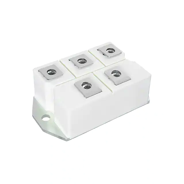
Vishay General Semiconductor - Diodes Division VS-131MT180C
Part No.:
VS-131MT180C
Manufacturer:
Vishay General Semiconductor - Diodes Division
Category:
Bridge Rectifiers
Package:
Module
Datasheet:
AetrixVS-131MT180C.pdf
Description:
BRIDGE RECT 3PHASE 1.8KV 218A
Quantity:
Payment:
Payment
Shipping:
Shipping

Inventory:32

Please send an inquiry. Send us your inquiry, and we will respond immediately.

Part Number
Quantity*
Price
Name*
Company
Email*
Comments

Product details

Overview

VS-131MT180C from Vishay Semiconductors is a three-phase bridge rectifier power module rated for 130 A average output current at 120 °C case temperature, with maximum repetitive peak reverse voltage (VRRM) of 1800 V and 3600 VRMS isolation voltage. It features electrically insulated case, high thermal conductivity package (MTC), and is designed for industrial-level heavy-duty AC/DC conversion in motor drives and UPS systems.

For engineers reviewing the VS-131MT180C datasheet, VS-131MT180C pinout, VS-131MT180C application, or VS-131MT180C equivalent, key selection criteria include its 1800 V blocking capability, 0.068 °C/W junction-to-case thermal resistance per module, surge rating of 1330 A (60 Hz, 8.3 ms), and UL approval (E78996) for safety-critical power conversion designs.

Technical Context

This module integrates six ultrafast recovery diodes in a single-phase-in, three-phase-out bridge configuration. Its MTC package provides electrical isolation between terminals and heatsink, enabling direct mounting without additional insulation hardware. Thermal performance is defined by RthJC = 0.068 °C/W (per module) and RthCS = 0.03 °C/W (case-to-heatsink, greased surface).

Electrical behavior includes dual forward voltage thresholds: VFT(TO)1 = 0.79 V (low-current region) and VFT(TO)2 = 0.96 V (high-current region), with corresponding slope resistances rf1 = 4.97 mΩ and rf2 = 4.63 mΩ at TJ = 150 °C. Maximum forward voltage drop is 2.05 V at 300 A peak and 25 °C junction temperature.

Key Specifications

Parameter Value and Actual Design Meaning
VRRM 1800 V - supports DC bus voltages up to 1270 V RMS in 3-phase 60 Hz systems with margin
IO (120° conduction) 130 A at TC = 120 °C - defines continuous output capability under typical rectifier duty cycle
IFSM (60 Hz) 1330 A - withstands short-term motor startup surges without fusing
RthJC (per module) 0.068 °C/W - enables efficient heat transfer to heatsink; limits ΔTJ to 8.8 °C at 130 A conduction loss
Visol 3600 VRMS - meets reinforced insulation requirements for industrial equipment per IEC 61800-5-1
Weight 235 g - compact mass for high-power density in space-constrained enclosures
TJ range –40 to +150 °C - supports operation in harsh ambient environments including outdoor inverters

Pinout & Package

The VS-131MT180C uses the MTC (Modular Three-phase Compact) package: 72 mm × 80 mm × 24.5 mm, with five M6 mounting screws, isolated baseplate, and terminal layout optimized for low-inductance three-phase AC input and DC output routing.

Pin/Terminal Circuit Role Design Meaning
AC1, AC2, AC3 Three-phase AC input terminals Accept 3-wire ungrounded AC supply; symmetric layout minimizes parasitic inductance imbalance
+ (Anode Common) Positive DC output terminal High-current path for full-wave rectified output; rated for 130 A continuous, 300 A peak
– (Cathode Common) Negative DC output terminal Return path for rectified current; electrically isolated from heatsink per UL E78996

Key Features

Feature Design Value
Electrically insulated case Enables direct bolt-down to grounded heatsink without isolation pads, reducing thermal interface resistance by ~0.03 °C/W
High surge capability (1330 A) Supports 60 Hz motor inrush currents exceeding 10× rated output without degradation
UL approval E78996 Validates compliance with UL 60747-1 for component-level safety in industrial power equipment
Optimized power-volume ratio Delivers 130 A / 1800 V in 142 cm³ volume - 22% smaller footprint than legacy 1200 V modules at same current rating
Low thermal resistance (0.068 °C/W) Reduces required heatsink size by ~35% compared to modules with RthJC > 0.1 °C/W at same power dissipation

Applications

Industrial Motor Drives Uninterruptible Power Supplies (UPS)

Use Scenario: Three-phase AC input rectification in 400 VAC variable-frequency drives for HVAC compressors and pumps.

IC Role / Device Role / Timing Role: Primary power conversion stage converting line AC to stable DC bus for inverter section.

Use Value: 1800 V VRRM ensures 2× safety margin over 400 VAC line-to-line peak (≈565 V), preventing avalanche failure during transients.

Use Scenario: Rectification stage in online double-conversion UPS systems handling 480 VAC input.

IC Role / Device Role / Timing Role: High-reliability AC/DC front-end delivering regulated DC to battery charger and inverter.

Use Value: 1330 A IFSM handles generator synchronization surges and utility fault ride-through without derating.

Renewable Energy Inverters Welding Power Supplies

Use Scenario: Grid-tied solar inverters with transformerless topology requiring reinforced isolation.

IC Role / Device Role / Timing Role: Isolated DC-link generation from three-phase utility or generator input.

Use Value: 3600 VRMS isolation meets IEC 62109-1 creepage/clearance requirements for Class II equipment.

Use Scenario: Primary rectification in medium-duty arc welding machines with 3-phase 400 VAC supply.

IC Role / Device Role / Timing Role: High-current, low-loss DC source feeding thyristor-controlled output stage.

Use Value: Dual forward voltage thresholds (0.79 V / 0.96 V) reduce conduction loss across 10–100% load range.

Equivalent & Alternatives

The following parts are listed as comparable options for similar three-phase bridge rectifier applications.

Alternative Part Technical Difference Application Difference Selection Advice
IXYS MDA130-18N1 Same 130 A / 1800 V rating; higher RthJC = 0.085 °C/W; non-insulated baseplate requires isolation pad Requires additional thermal interface material and creepage spacing design effort Preferred where cost sensitivity outweighs thermal optimization and isolation simplicity
Infineon TD130N18KO 130 A / 1800 V; lower IFSM = 1100 A; RthJC = 0.072 °C/W; UL recognized but not approved Limited surge margin in motor drive applications with high inertia loads Suitable for fixed-speed industrial rectifiers where transient stress is well characterized

Compared with MDA130-18N1 and TD130N18KO, the VS-131MT180C delivers superior thermal efficiency (0.068 °C/W), certified isolation (UL E78996), and highest surge robustness (1330 A), making it optimal for high-reliability, space-constrained, and safety-certified industrial power systems.

Availability

VS-131MT180C is available at Aetrix Electronics and suitable for industrial motor drives, uninterruptible power supplies, and renewable energy inverters requiring stable component supply, long-term lifecycle support, and traceable sourcing for safety-critical designs.

Supply support for VS-131MT180C includes scheduled delivery planning, volume procurement assistance, BOM continuity management, traceable sourcing, and lifecycle availability coordination for OEM customers, industrial embedded developers, connected-device designers, and electronics production programs.

Manufacturer

Vishay Semiconductors is a global leader in discrete semiconductors and passive components, specializing in high-reliability power devices for industrial, automotive, and computing markets.

The VS-131MT180C belongs to Vishay's MTC-series power modules, engineered specifically for compact, high-efficiency three-phase AC/DC conversion in demanding industrial environments where thermal performance and safety certification are critical.

FAQ

What is the maximum allowable case temperature for continuous operation of the VS-131MT180C?

The VS-131MT180C is rated for continuous operation at a maximum case temperature (TC) of 120 °C when delivering its full 130 A average output current under 120° conduction angle. Exceeding this temperature requires derating per the manufacturer's current vs. case temperature curve (Fig. 1), and sustained operation above 120 °C risks accelerated parameter drift and reduced lifetime.

Does the VS-131MT180C require an external isolation pad when mounted to a heatsink?

No, the VS-131MT180C does not require an external isolation pad. Its MTC package features an electrically insulated baseplate certified to 3600 VRMS and UL-approved (E78996), allowing direct mounting to a grounded heatsink while maintaining reinforced insulation integrity without added thermal resistance.

What is the forward voltage behavior of the VS-131MT180C across its operating current range?

The VS-131MT180C exhibits two-region forward conduction: a low-slope region (VFT(TO)1 = 0.79 V, rf1 = 4.97 mΩ) below π × IF(AV), and a high-slope region (VFT(TO)2 = 0.96 V, rf2 = 4.63 mΩ) above that threshold. This dual-threshold behavior reduces total conduction loss across partial-load conditions common in variable-speed drives.

How does the thermal resistance of the VS-131MT180C change with conduction angle?

The junction-to-case thermal resistance (RthJC) of the VS-131MT180C varies with conduction angle: it is 0.068 °C/W at DC, 0.063 °C/W at 120° rectangular conduction, and increases to 0.109 °C/W at 60° conduction. These values reflect dynamic thermal impedance during pulsed operation and must be used in transient thermal modeling for surge conditions.

Is the VS-131MT180C suitable for use in transformerless photovoltaic inverters?

Yes, the VS-131MT180C is suitable for transformerless PV inverters due to its 3600 VRMS isolation rating and UL E78996 approval, which satisfy reinforced insulation requirements per IEC 62109-1. Its 1800 V VRRM also provides sufficient margin against DC-side transients in bipolar string configurations.

VS-131MT180C Specifications

Product attributes
Attribute value
Manufacturer:
Vishay General Semiconductor - Diodes Division
Series:
-
Package/Case:
Module
Packaging:
Box
Product Status:
Active
Diode Type:
Three Phase
Technology:
Standard
Voltage - Peak Reverse (Max):
1.8 kV
Current - Average Rectified (Io):
218 A
Voltage - Forward (Vf) (Max) @ If:
2.05 V @ 300 A
Current - Reverse Leakage @ Vr:
12 mA @ 1800 V
Operating Temperature:
-40°C ~ 150°C (TJ)
Grade:
-
Qualification:
-
Mounting Type:
Chassis Mount
Supplier Device Package:
-

VS-131MT180C FAQ

1.How can I place an order for VS-131MT180C through Aetrix?

Please submit a Request for Quotation (RFQ) for VS-131MT180C on Aetrix. Our sales agent will provide a competitive quotation and guide you through the order confirmation once you accept the terms.

2.Are the price and stock information for VS-131MT180C reliable?

The price and inventory of VS-131MT180C are updated periodically and may fluctuate due to market conditions. Stock and pricing data are typically refreshed every 24 hours. Quotation validity for VS-131MT180C is usually 5 days.

3.What payment methods are accepted for VS-131MT180C?

We accept Wire Transfer, PayPal, Credit Card, Western Union, MoneyGram, and Escrow for VS-131MT180C transactions.

Note: Certain payment methods may incur a processing fee.

4.How is shipping managed for VS-131MT180C?

VS-131MT180C orders can be shipped via leading logistics carriers, including DHL, UPS, FedEx, TNT, or Registered Mail.

Once your VS-131MT180C order is processed, you will receive an email with the shipment details and tracking number.

Note: Tracking information may take up to 24 hours to appear. Express delivery typically takes 3–5 business days.

5.How can I obtain technical support or documentation for VS-131MT180C?

For technical support, including VS-131MT180C datasheets, pinout diagrams, or application guidance, please contact our engineering support team. They can provide detailed documentation and assistance for your VS-131MT180C requirements.

6.How does Aetrix verify that VS-131MT180C is sourced from the original manufacturer or authorized distributors?

All VS-131MT180C products on Aetrix are procured from qualified distributors and authorized channels. Our dedicated quality assurance team conducts strict verification, including traceability checks and, if necessary, third-party testing. This ensures that VS-131MT180C meets industry standards.

7.What is the process for return or replacement of VS-131MT180C?

All VS-131MT180C units undergo pre-shipment inspection (PSI). If there is an issue with VS-131MT180C, returns or replacements are accepted under the following conditions:

1.Quantity discrepancies, incorrect items, or visible external defects (such as breakage or corrosion), acknowledged by Aetrix.

2.The issue is reported within 90 days of delivery.

3.The VS-131MT180C part is unused and in its original packaging.

Return procedure for VS-131MT180C:

1.Submit a request within 90 days.

2.Obtain a Return Material Authorization (RMA) from Aetrix.

VS-131MT180C Tags
  • VS-131MT180C
  • VS-131MT180C PDF
  • VS-131MT180C Datasheet
  • VS-131MT180C Specifications
  • VS-131MT180C Images
  • Vishay General Semiconductor - Diodes Division
  • Vishay General Semiconductor - Diodes Division VS-131MT180C
  • Buy VS-131MT180C
  • VS-131MT180C Price
  • VS-131MT180C Distributor
  • VS-131MT180C Supplier
  • VS-131MT180C Wholesale
Related Products
HDS10M-13
HDS10M-13

Diodes Incorporated

CD-MBL106S
CD-MBL106S

Bourns Inc.

MB10S-13
MB10S-13

Diodes Incorporated

CD-MBL206SL
CD-MBL206SL

Bourns Inc.

MB4S-TP
MB4S-TP

Micro Commercial Co

MB6S-TP
MB6S-TP

Micro Commercial Co

CD-MBL210S
CD-MBL210S

Bourns Inc.

BAS3007ARPPE6327HTSA1

Infineon Technologies
DF02M
DF02M

Diodes Incorporated

CD-MBL210SL
CD-MBL210SL

Bourns Inc.

DF04M
DF04M

Diodes Incorporated

DF01M
DF01M

Diodes Incorporated

Tech Hub

Search

Search

PRODUCT

PRODUCT

PHONE

PHONE

USER

USER