Send an Inquiry

To receive a quote for your project, please fill in the following information, and we’ll get back to you promptly.

Name*
Company*
Email Address*
Phone/WhatsApp
Part Number*
Quantity*
Message
Submit Inventory List

Please fill in the following information, and we’ll get back to you promptly.

Name*
Company*
Email Address*
Phone/WhatsApp
Upload My List
Message

Vishay General Semiconductor - Diodes Division VS-26MB10A
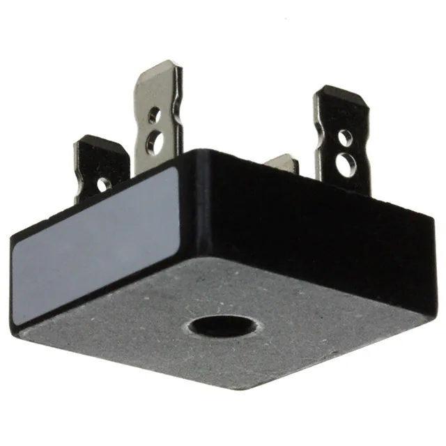
Part No.:
VS-26MB10A
Manufacturer:
Vishay General Semiconductor - Diodes Division
Category:
Bridge Rectifiers
Package:
4-Square, D-34
Datasheet:
AetrixVS-26MB10A.pdf
Description:
BRIDGE RECT 1PHASE 100V 25A D-34
Quantity:
Payment:
Payment
Shipping:
Shipping

Inventory:2,585

Please send an inquiry. Send us your inquiry, and we will respond immediately.

Part Number
Quantity*
Price
Name*
Company
Email*
Comments

Product details

Overview

VS-26MB10A from Infineon Technologies is a single-phase bridge rectifier module rated for 10 A average forward current (resistive/inductive load), 100 V repetitive peak reverse voltage (VRRM), and maximum junction temperature of 150 °C. It features electrically insulated case, 3.5 K/W junction-to-case thermal resistance, and UL E62320 approval - designed for compact AC/DC power supplies in instrumentation and general-purpose industrial equipment.

For engineers reviewing the VS-26MB10A datasheet, VS-26MB10A pinout, VS-26MB10A application, or VS-26MB10A equivalent, key selection criteria include its 100 V VRRM rating, 1.3 V max forward voltage at 31.4 A pulse, 10 µA max reverse leakage per diode at 25 °C, and compatibility with push-on/wrap-around/solder termination methods.

Technical Context

The VS-26MB10A integrates four silicon diodes in a single-phase full-wave bridge configuration within an epoxy-encapsulated, electrically insulated package. Its thermal design supports direct mounting to heatsinks via center-hole fixing, with RthJC = 3.5 K/W and RthCS = 0.2 K/W (greased interface).

It operates across -40 °C to +150 °C junction temperature range and delivers stable rectification under capacitive, inductive, or resistive loads. The device sustains non-repetitive surge currents up to 148 A (10 ms, 50 Hz) and exhibits low forward conduction losses via VF(TO)1 = 1.00 V and rt1 = 15.4 mΩ at TJ max.

Key Specifications

Parameter Value and Actual Design Meaning
VRRM 100 V - Maximum repetitive reverse voltage each diode withstands without breakdown; defines safe AC input voltage ceiling (e.g., ≤70 V RMS).
IO (AV) 10 A - Continuous DC output current capability at TC = 65 °C with resistive/inductive load; determines sustained power delivery capacity.
IFSM (50 Hz) 148 A - Peak one-cycle surge current tolerance (10 ms); critical for handling inrush during cold-start of transformer-coupled supplies.
VF(M) 1.3 V - Max forward voltage drop at TJ = 25 °C, IFM = π × IO(AV) ≈ 31.4 A, tp = 400 µs; directly impacts conduction loss and thermal rise.
RthJC 3.5 K/W - Junction-to-case thermal resistance per bridge; enables thermal modeling when mounted on heatsink with known RthCS.
IRRM 10 µA - Max DC reverse current per diode at VRRM and TJ = 25 °C; ensures minimal leakage in high-impedance or precision sensing circuits.
VINS 2700 V RMS - Isolation voltage between baseplate and internal circuitry (50 Hz, 1 s); certifies safety in mains-connected equipment.

Pinout & Package

VS-26MB10A uses a 4-terminal, single-phase bridge rectifier package with universal 3-way termination: push-on faston, wrap-around, or solder. Case is electrically insulated and features center mounting hole (M4, torque 2.0 Nm). Approximate weight: 20 g.

Pin/Terminal Circuit Role Design Meaning
AC1 AC Input Terminal 1 One leg of AC input; connects to transformer secondary or line input; shares common cathode node internally with AC2.
AC2 AC Input Terminal 2 Second leg of AC input; completes full-wave bridge input path; symmetrical with AC1 for bidirectional conduction.
+ (DC+) Positive DC Output Anode of both upper diodes; delivers rectified positive output; must connect to bulk capacitor or downstream regulator.
– (DC–) Negative DC Output / Common Return Cathode of both lower diodes; serves as system ground reference and return path for DC load current.

Key Features

Feature Design Value
Electrically insulated case Enables direct mounting to grounded heatsinks without isolation hardware; reduces BOM count and assembly steps.
Universal 3-way terminals Supports push-on (200 N max axial force), wrap-around, or solder termination - simplifies integration across prototyping and production.
UL E62320 approval Validates compliance with safety standards for double-insulated mains-connected equipment; eliminates need for additional certification testing.
High power/volume ratio Delivers 10 A rectification in compact encapsulated module (typ. 20 g, ~25 mm × 20 mm footprint); saves PCB space vs discrete diode solutions.
Low thermal resistance RthJC = 3.5 K/W and RthCS = 0.2 K/W (greased) enable efficient heat transfer - supports higher ambient temperatures or reduced heatsink size.

Applications

Industrial Power Supplies Test & Measurement Equipment

Use Scenario: AC/DC conversion in benchtop power supplies with adjustable output and low ripple requirements.

IC Role / Device Role / Timing Role: Single-phase bridge rectifier converting 50/60 Hz transformer output to pulsating DC prior to filtering and regulation.

Use Value: Low VF and tight IRRM ensure stable no-load voltage and minimal standby loss; UL approval supports CE-marked product compliance.

Use Scenario: Signal conditioning front-end in portable oscilloscopes and multimeters requiring isolated, low-noise DC rails.

IC Role / Device Role / Timing Role: Mains-input rectification stage providing isolated ±15 V analog supply rails for op-amps and ADC references.

Use Value: Electrically insulated case eliminates need for insulating washers; compact size fits constrained enclosure layouts.

Motor Control Auxiliary Supplies LED Driver Input Stages

Use Scenario: Auxiliary 24 V DC supply for gate drivers and logic in 3-phase inverter systems operating from 115 V AC mains.

IC Role / Device Role / Timing Role: Primary rectifier feeding unregulated DC bus that powers isolated DC/DC converters for control circuitry.

Use Value: 148 A IFSM handles repeated motor startup surges; RthJC = 3.5 K/W allows thermal coupling to main inverter heatsink.

Use Scenario: Input rectification in constant-current LED drivers for commercial lighting, where EMI and efficiency are tightly controlled.

IC Role / Device Role / Timing Role: First-stage AC-to-DC conversion before PFC controller and buck converter stages.

Use Value: 10 µA IRRM minimizes leakage-induced offset in current-sense feedback paths; VRRM = 100 V matches 70 V RMS input designs.

Equivalent & Alternatives

The following parts are listed as comparable options for similar single-phase bridge rectifier applications.

Alternative Part Technical Difference Application Difference Selection Advice
Vishay VS-GBPC10A Same 10 A IO, 100 V VRRM, but TO-247-4L package with non-insulated case; RthJC = 2.5 K/W. Requires insulating kit for heatsink mounting; better thermal performance but adds assembly complexity. Select when thermal budget is tighter and isolation can be added externally.
ON Semiconductor GBPC1004 10 A IO, 400 V VRRM, same MB-series footprint; RthJC = 3.0 K/W; IRRM = 5 µA at 25 °C. Higher voltage rating suits 230 V AC inputs; lower leakage benefits precision analog supplies. Select when designing for dual-voltage (115/230 V) global markets or ultra-low-leakage requirements.

Compared with VS-26MB10A, VS-GBPC10A offers superior thermal resistance but requires external insulation, while GBPC1004 provides higher VRRM and lower IRRM at the cost of over-spec'ing for 100 V applications - making VS-26MB10A optimal for cost-sensitive, safety-certified 115 V AC instrumentation designs.

Availability

VS-26MB10A is available at Aetrix Electronics and suitable for industrial power supplies, test & measurement equipment, and motor control auxiliary supplies requiring stable component supply, long-term lifecycle support, and UL-recognized safety compliance.

Supply support for VS-26MB10A includes scheduled delivery planning, volume procurement assistance, BOM continuity management, traceable sourcing, and lifecycle availability coordination for OEM customers, industrial embedded developers, connected-device designers, and electronics production programs.

Manufacturer

Infineon Technologies is a German semiconductor manufacturer specializing in power semiconductors, microcontrollers, and sensor solutions for automotive, industrial, and power management applications.

The VS-26MB10A belongs to Infineon's MB-series single-phase bridge rectifier family, engineered for compact, reliable AC/DC conversion in safety-critical instrumentation and general-purpose industrial equipment.

FAQ

What is the maximum allowable case temperature for continuous operation of the VS-26MB10A?

The VS-26MB10A supports continuous operation at a maximum case temperature (TC) of 65 °C when delivering its rated 10 A average forward current into resistive or inductive loads. Exceeding this temperature requires derating per the current ratings curves in Bulletin I2715 - for example, at TC = 50 °C, IO increases to ~12.5 A. Thermal design must account for RthJC = 3.5 K/W and RthCS = 0.2 K/W to maintain junction temperature below 150 °C.

Does the VS-26MB10A require external insulation when mounted to a metal heatsink?

No - the VS-26MB10A features an electrically insulated case certified to 2700 V RMS isolation (VINS), enabling direct mounting to grounded or floating metal heatsinks without insulating pads or sleeves. This simplifies mechanical design and improves thermal reliability. Mounting torque must be maintained at 2.0 Nm ±10% using the center fixing hole, and the interface surface must be smooth, flat, and greased to achieve the specified RthCS = 0.2 K/W.

What is the forward voltage drop of the VS-26MB10A under typical operating conditions?

The VS-26MB10A exhibits a maximum forward voltage drop (VFM) of 1.3 V at TJ = 25 °C, with instantaneous forward current IFM = π × IO(AV) ≈ 31.4 A and pulse width tp = 400 µs. At elevated junction temperature (TJ = 150 °C), the threshold voltage VF(TO)1 is 1.00 V and slope resistance rt1 is 15.4 mΩ - meaning VF rises linearly with current above ~5.2 A. This behavior is critical for calculating conduction losses in thermal models.

Can the VS-26MB10A be used in capacitive-load applications?

Yes, the VS-26MB10A supports capacitive-load operation, though with reduced current rating: 8 A average forward current (vs. 10 A for resistive/inductive loads) at TC = 65 °C. This derating accounts for higher peak currents and increased thermal stress caused by capacitor charging transients. Designers must verify surge current limits (IFSM = 148 A) and I²t fusing values (110 A²s at 10 ms) against their specific input capacitor size and inrush profile.

Is the VS-26MB10A RoHS compliant and halogen-free?

Yes, the VS-26MB10A conforms to RoHS Directive 2011/65/EU and is halogen-free per IEC 61249-2-21. Infineon documents this compliance in material declarations aligned with IPC-1752A, and the device carries the "RoHS-compliant" marking on its packaging and datasheet. No exemptions apply - all lead content is below 0.1 wt%, and brominated flame retardants are absent from the epoxy encapsulant.

VS-26MB10A Specifications

Product attributes
Attribute value
Manufacturer:
Vishay General Semiconductor - Diodes Division
Series:
-
Package/Case:
4-Square, D-34
Packaging:
Bulk
Product Status:
Active
Diode Type:
Single Phase
Technology:
Standard
Voltage - Peak Reverse (Max):
100 V
Current - Average Rectified (Io):
25 A
Voltage - Forward (Vf) (Max) @ If:
-
Current - Reverse Leakage @ Vr:
10 µA @ 100 V
Operating Temperature:
-40°C ~ 150°C (TJ)
Grade:
-
Qualification:
-
Mounting Type:
QC Terminal
Supplier Device Package:
D-34

VS-26MB10A FAQ

1.How can I place an order for VS-26MB10A through Aetrix?

Please submit a Request for Quotation (RFQ) for VS-26MB10A on Aetrix. Our sales agent will provide a competitive quotation and guide you through the order confirmation once you accept the terms.

2.Are the price and stock information for VS-26MB10A reliable?

The price and inventory of VS-26MB10A are updated periodically and may fluctuate due to market conditions. Stock and pricing data are typically refreshed every 24 hours. Quotation validity for VS-26MB10A is usually 5 days.

3.What payment methods are accepted for VS-26MB10A?

We accept Wire Transfer, PayPal, Credit Card, Western Union, MoneyGram, and Escrow for VS-26MB10A transactions.

Note: Certain payment methods may incur a processing fee.

4.How is shipping managed for VS-26MB10A?

VS-26MB10A orders can be shipped via leading logistics carriers, including DHL, UPS, FedEx, TNT, or Registered Mail.

Once your VS-26MB10A order is processed, you will receive an email with the shipment details and tracking number.

Note: Tracking information may take up to 24 hours to appear. Express delivery typically takes 3–5 business days.

5.How can I obtain technical support or documentation for VS-26MB10A?

For technical support, including VS-26MB10A datasheets, pinout diagrams, or application guidance, please contact our engineering support team. They can provide detailed documentation and assistance for your VS-26MB10A requirements.

6.How does Aetrix verify that VS-26MB10A is sourced from the original manufacturer or authorized distributors?

All VS-26MB10A products on Aetrix are procured from qualified distributors and authorized channels. Our dedicated quality assurance team conducts strict verification, including traceability checks and, if necessary, third-party testing. This ensures that VS-26MB10A meets industry standards.

7.What is the process for return or replacement of VS-26MB10A?

All VS-26MB10A units undergo pre-shipment inspection (PSI). If there is an issue with VS-26MB10A, returns or replacements are accepted under the following conditions:

1.Quantity discrepancies, incorrect items, or visible external defects (such as breakage or corrosion), acknowledged by Aetrix.

2.The issue is reported within 90 days of delivery.

3.The VS-26MB10A part is unused and in its original packaging.

Return procedure for VS-26MB10A:

1.Submit a request within 90 days.

2.Obtain a Return Material Authorization (RMA) from Aetrix.

VS-26MB10A Tags
  • VS-26MB10A
  • VS-26MB10A PDF
  • VS-26MB10A Datasheet
  • VS-26MB10A Specifications
  • VS-26MB10A Images
  • Vishay General Semiconductor - Diodes Division
  • Vishay General Semiconductor - Diodes Division VS-26MB10A
  • Buy VS-26MB10A
  • VS-26MB10A Price
  • VS-26MB10A Distributor
  • VS-26MB10A Supplier
  • VS-26MB10A Wholesale
Related Products
HDS10M-13
HDS10M-13

Diodes Incorporated

CD-MBL106S
CD-MBL106S

Bourns Inc.

MB10S-13
MB10S-13

Diodes Incorporated

CD-MBL206SL
CD-MBL206SL

Bourns Inc.

MB4S-TP
MB4S-TP

Micro Commercial Co

MB6S-TP
MB6S-TP

Micro Commercial Co

CD-MBL210S
CD-MBL210S

Bourns Inc.

BAS3007ARPPE6327HTSA1

Infineon Technologies
DF02M
DF02M

Diodes Incorporated

CD-MBL210SL
CD-MBL210SL

Bourns Inc.

DF04M
DF04M

Diodes Incorporated

DF01M
DF01M

Diodes Incorporated

Tech Hub

Search

Search

PRODUCT

PRODUCT

PHONE

PHONE

USER

USER