Send an Inquiry

To receive a quote for your project, please fill in the following information, and we’ll get back to you promptly.

Name*
Company*
Email Address*
Phone/WhatsApp
Part Number*
Quantity*
Message
Submit Inventory List

Please fill in the following information, and we’ll get back to you promptly.

Name*
Company*
Email Address*
Phone/WhatsApp
Upload My List
Message

Vishay General Semiconductor - Diodes Division VS-301MT180C
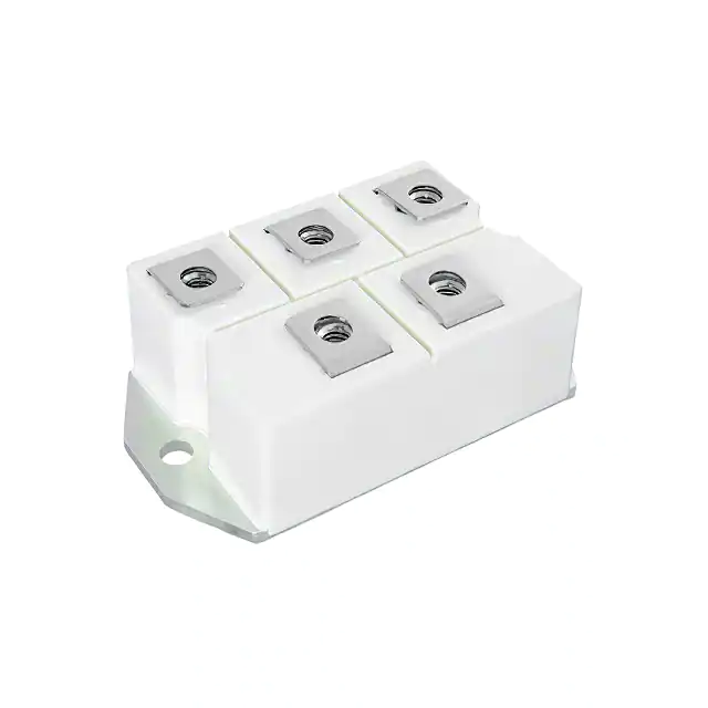
Part No.:
VS-301MT180C
Manufacturer:
Vishay General Semiconductor - Diodes Division
Category:
Bridge Rectifiers
Package:
Module
Datasheet:
AetrixVS-301MT180C.pdf
Description:
BRIDGE RECT 3PHASE 1.8KV 300A
Quantity:
Payment:
Payment
Shipping:
Shipping

Inventory:13

Please send an inquiry. Send us your inquiry, and we will respond immediately.

Part Number
Quantity*
Price
Name*
Company
Email*
Comments

Product details

Overview

VS-301MT180C from Vishay Semiconductors is a three-phase bridge rectifier power module rated for 300 A average output current at 100 °C case temperature, with maximum repetitive peak reverse voltage (VRRM) of 1800 V and 3600 VRMS isolation voltage. It features electrically insulated case, high thermal conductivity packaging, and is designed for industrial-level heavy-duty AC/DC conversion in motor drives and UPS systems.

For engineers reviewing the VS-301MT180C datasheet, VS-301MT180C pinout, VS-301MT180C application, or VS-301MT180C equivalent, key selection considerations include its MTC package mounting torque (5 Nm), junction-to-case thermal resistance (0.23 °C/W per junction), surge capability (2512 A at 60 Hz), forward voltage drop (1.7 V at 300 A, 25 °C), and UL approval (E78996).

Technical Context

The VS-301MT180C implements a fully encapsulated three-phase full-wave diode bridge configuration with six series-connected silicon diode junctions arranged in standard 3-leg topology. Its electrically insulated copper baseplate enables direct mounting to heatsinks without additional isolation hardware while maintaining 3600 VRMS dielectric strength.

Thermal performance is defined by RthJC = 0.23 °C/W per junction under DC operation and RthCS = 0.03 °C/W (typical) from case to heatsink with greased, flat mounting surface. Conduction-angle derating applies: maximum output current drops from 300 A at 120° conduction to 258 A at DC, per datasheet Table "MAJOR RATINGS AND CHARACTERISTICS".

Key Specifications

Parameter Value and Actual Design Meaning
VRRM 1800 V - Maximum repetitive reverse voltage per diode; defines AC input voltage headroom before breakdown in rectifier operation.
IO (120°) 300 A - Maximum average DC output current at 100 °C case temperature with 120° conduction angle; sets continuous load capacity.
IFSM (60 Hz) 2512 A - Non-repetitive surge current rating at 60 Hz, t = 8.3 ms; determines short-circuit withstand capability during fault events.
VFM (300 A) 1.7 V - Forward voltage drop per junction at 300 A peak and 25 °C; directly impacts conduction loss and thermal design margin.
RthJC (per junction) 0.23 °C/W - Junction-to-case thermal resistance under DC operation; used with power loss to calculate max junction temperature.
Visol 3600 VRMS - RMS isolation voltage between all terminals and baseplate; satisfies safety requirements for industrial equipment insulation.
Mounting torque 5 Nm - Required screw torque for M6 fasteners to ensure optimal thermal interface and mechanical reliability per MTC outline spec.

Pinout & Package

The VS-301MT180C uses the MTC (Modular Three-phase Compact) package: a rectangular, insulated-base power module with six solderable terminals and five M6 mounting holes. Dimensions are 94 mm × 72 mm × 24.5 mm (L × W × H), weight ≈ 235 g. Baseplate is electrically isolated and thermally conductive.

Pin/Terminal Circuit Role Design Meaning
AC1, AC2, AC3 Three-phase AC inputs Accept line-to-line AC input; each connects to one leg of the three-phase bridge; symmetrical layout supports balanced conduction.
+ (Anode common) Positive DC output Common anode connection point for all upper diodes; carries full rectified DC output current to load or filter capacitor.
– (Cathode common) Negative DC output / return Common cathode connection point for all lower diodes; serves as DC return path and reference for output voltage regulation.

Key Features

Feature Design Value
UL-approved insulation UL file E78996 certified; enables use in safety-critical industrial equipment without additional isolation barriers.
High surge capability 2512 A non-repetitive surge current at 60 Hz (8.3 ms); supports reliable startup and fault tolerance in motor drive inverters.
Electrically insulated case Baseplate provides 3600 VRMS isolation; eliminates need for insulating washers or pads when mounted to grounded heatsinks.
Optimized power-volume ratio 300 A / 1800 V rating in 94 × 72 × 24.5 mm footprint; reduces system size versus discrete diode solutions with equivalent ratings.
Thermally robust mounting Specified 5 Nm M6 torque with grease and re-torque recommendation ensures stable RthCS ≤ 0.03 °C/W over lifetime.

Applications

Industrial Motor Drives Uninterruptible Power Supplies (UPS)

Use Scenario: Three-phase AC input rectification in variable-frequency drives for HVAC compressors and conveyor systems.

IC Role / Device Role / Timing Role: Primary AC/DC conversion stage delivering regulated DC bus voltage to IGBT inverter stage.

Use Value: 300 A continuous rating and 1800 V blocking support 400–480 VAC industrial mains with margin; insulated base simplifies thermal management in compact enclosures.

Use Scenario: Input rectification in online double-conversion UPS systems handling critical IT loads.

IC Role / Device Role / Timing Role: Front-end rectifier converting utility AC to stable DC bus for battery charging and inverter feeding.

Use Value: High surge rating (2512 A) handles generator transients and brownout recovery; UL certification meets UL 1778 safety requirements.

Welding Power Supplies Renewable Energy Inverters

Use Scenario: Rectifying three-phase generator output in portable arc welding machines with high peak-current demands.

IC Role / Device Role / Timing Role: High-current, low-loss AC-to-DC conversion stage preceding DC-link filtering and inverter modulation.

Use Value: Low forward voltage (1.7 V @ 300 A) minimizes conduction loss during duty-cycle-intensive welding arcs; rugged MTC package resists vibration and thermal cycling.

Use Scenario: Grid-tie inverter front-end rectification in bi-directional energy storage systems using three-phase utility coupling.

IC Role / Device Role / Timing Role: Bidirectional AC/DC interface enabling both grid charging and battery discharge modes.

Use Value: 150 °C max junction temperature and -40 °C min storage rating support outdoor deployment; 3600 VRMS isolation meets IEC 62109 insulation requirements.

Equivalent & Alternatives

The following parts are listed as comparable options for similar three-phase bridge rectifier applications.

Alternative Part Technical Difference Application Difference Selection Advice
IXYS MDA300-16N1 1600 V VRRM, 300 A IO, TO-247-3 isolated package; higher RthJC (0.35 °C/W) and no UL file. Limited to 1600 V systems; requires external isolation hardware; not UL-certified for safety-critical deployments. Select when cost sensitivity outweighs safety certification needs and voltage margin is sufficient.
Infineon DDB6U180N16RR 1800 V VRRM, 250 A IO, dual-diode module; lower current rating but integrated NTC sensor and tighter VFM tolerance (±0.05 V). Suitable only for <250 A designs; NTC enables closed-loop thermal monitoring but adds complexity. Prefer where real-time temperature feedback is required and output current can be reduced by 17%.

Compared with MDA300-16N1 and DDB6U180N16RR, the VS-301MT180C uniquely combines 1800 V rating, 300 A capacity, UL certification, and integrated insulation-making it the only option qualified for high-power industrial rectification without supplemental safety components.

Availability

VS-301MT180C is available at Aetrix Electronics and suitable for industrial motor drives, uninterruptible power supplies, welding equipment, and renewable energy inverters requiring stable component supply, long-term lifecycle assurance, and traceable sourcing.

Supply support for VS-301MT180C includes scheduled delivery planning, volume procurement assistance, BOM continuity management, traceable sourcing, and lifecycle availability coordination for OEM customers, industrial embedded developers, connected-device designers, and electronics production programs.

Manufacturer

Vishay Intertechnology is a global semiconductor manufacturer specializing in discrete components, sensors, and passive elements, with emphasis on reliability, precision, and power efficiency.

The VS-301MT180C belongs to Vishay's MTC-series power modules, engineered specifically for high-current, high-voltage industrial rectification where thermal stability, electrical isolation, and safety compliance are mandatory.

FAQ

What is the maximum allowable case temperature for continuous operation of the VS-301MT180C?

The VS-301MT180C supports continuous operation up to 110 °C case temperature (TC) at rated 300 A output with 120° conduction angle, as specified in the "MAJOR RATINGS AND CHARACTERISTICS" table. Exceeding this temperature requires derating per Fig. 1 in the datasheet. The VS-301MT180C must be mounted with proper thermal interface material and 5 Nm torque to maintain safe junction temperatures below 150 °C.

Does the VS-301MT180C require external isolation hardware when mounted to a grounded heatsink?

No. The VS-301MT180C features an electrically insulated copper baseplate rated for 3600 VRMS isolation, eliminating the need for mica washers, silicone pads, or other external isolation layers. This insulation is certified under UL file E78996. The VS-301MT180C achieves full safety compliance with direct mounting to grounded heatsinks when installed per specified torque and surface finish requirements.

What is the forward voltage drop of the VS-301MT180C at rated current and room temperature?

The VS-301MT180C exhibits a maximum forward voltage drop (VFM) of 1.7 V per junction at 300 A peak forward current and 25 °C junction temperature. This value is measured under standardized test conditions and directly determines conduction losses in the rectifier stage. At elevated temperatures (e.g., 150 °C), VFM decreases slightly due to semiconductor physics, but thermal design must prioritize junction temperature control to sustain reliability.

Can the VS-301MT180C be used in 60 Hz and 50 Hz power systems interchangeably?

Yes. The VS-301MT180C is rated for both 50 Hz and 60 Hz operation, with distinct surge current specifications: 2400 A (50 Hz, 10 ms) and 2512 A (60 Hz, 8.3 ms). Its thermal and electrical characteristics are validated across both frequencies, and the conduction-angle derating curves apply equally. System designers may select the appropriate IFSM value based on local grid frequency when sizing protection devices for the VS-301MT180C.

What is the thermal resistance from junction to case (RthJC) for the VS-301MT180C, and how is it applied in thermal design?

The VS-301MT180C has a junction-to-case thermal resistance of 0.23 °C/W per diode junction under DC operation. Since the module contains six diodes in three-phase bridge configuration, total power dissipation must be distributed across all junctions. Thermal design uses RthJC together with measured or calculated power loss (e.g., from VFM × IAV + rf × I²R) to determine junction temperature rise above case temperature. The VS-301MT180C datasheet provides ΔRthJC correction factors for non-DC conduction angles.

VS-301MT180C Specifications

Product attributes
Attribute value
Manufacturer:
Vishay General Semiconductor - Diodes Division
Series:
-
Package/Case:
Module
Packaging:
Box
Product Status:
Active
Diode Type:
Three Phase
Technology:
Standard
Voltage - Peak Reverse (Max):
1.8 kV
Current - Average Rectified (Io):
300 A
Voltage - Forward (Vf) (Max) @ If:
1.7 V @ 300 A
Current - Reverse Leakage @ Vr:
12 mA @ 1800 V
Operating Temperature:
-40°C ~ 150°C (TJ)
Grade:
-
Qualification:
-
Mounting Type:
Chassis Mount
Supplier Device Package:
-

VS-301MT180C FAQ

1.How can I place an order for VS-301MT180C through Aetrix?

Please submit a Request for Quotation (RFQ) for VS-301MT180C on Aetrix. Our sales agent will provide a competitive quotation and guide you through the order confirmation once you accept the terms.

2.Are the price and stock information for VS-301MT180C reliable?

The price and inventory of VS-301MT180C are updated periodically and may fluctuate due to market conditions. Stock and pricing data are typically refreshed every 24 hours. Quotation validity for VS-301MT180C is usually 5 days.

3.What payment methods are accepted for VS-301MT180C?

We accept Wire Transfer, PayPal, Credit Card, Western Union, MoneyGram, and Escrow for VS-301MT180C transactions.

Note: Certain payment methods may incur a processing fee.

4.How is shipping managed for VS-301MT180C?

VS-301MT180C orders can be shipped via leading logistics carriers, including DHL, UPS, FedEx, TNT, or Registered Mail.

Once your VS-301MT180C order is processed, you will receive an email with the shipment details and tracking number.

Note: Tracking information may take up to 24 hours to appear. Express delivery typically takes 3–5 business days.

5.How can I obtain technical support or documentation for VS-301MT180C?

For technical support, including VS-301MT180C datasheets, pinout diagrams, or application guidance, please contact our engineering support team. They can provide detailed documentation and assistance for your VS-301MT180C requirements.

6.How does Aetrix verify that VS-301MT180C is sourced from the original manufacturer or authorized distributors?

All VS-301MT180C products on Aetrix are procured from qualified distributors and authorized channels. Our dedicated quality assurance team conducts strict verification, including traceability checks and, if necessary, third-party testing. This ensures that VS-301MT180C meets industry standards.

7.What is the process for return or replacement of VS-301MT180C?

All VS-301MT180C units undergo pre-shipment inspection (PSI). If there is an issue with VS-301MT180C, returns or replacements are accepted under the following conditions:

1.Quantity discrepancies, incorrect items, or visible external defects (such as breakage or corrosion), acknowledged by Aetrix.

2.The issue is reported within 90 days of delivery.

3.The VS-301MT180C part is unused and in its original packaging.

Return procedure for VS-301MT180C:

1.Submit a request within 90 days.

2.Obtain a Return Material Authorization (RMA) from Aetrix.

VS-301MT180C Tags
  • VS-301MT180C
  • VS-301MT180C PDF
  • VS-301MT180C Datasheet
  • VS-301MT180C Specifications
  • VS-301MT180C Images
  • Vishay General Semiconductor - Diodes Division
  • Vishay General Semiconductor - Diodes Division VS-301MT180C
  • Buy VS-301MT180C
  • VS-301MT180C Price
  • VS-301MT180C Distributor
  • VS-301MT180C Supplier
  • VS-301MT180C Wholesale
Related Products
HDS10M-13
HDS10M-13

Diodes Incorporated

CD-MBL106S
CD-MBL106S

Bourns Inc.

MB10S-13
MB10S-13

Diodes Incorporated

CD-MBL206SL
CD-MBL206SL

Bourns Inc.

MB4S-TP
MB4S-TP

Micro Commercial Co

MB6S-TP
MB6S-TP

Micro Commercial Co

CD-MBL210S
CD-MBL210S

Bourns Inc.

BAS3007ARPPE6327HTSA1

Infineon Technologies
DF02M
DF02M

Diodes Incorporated

CD-MBL210SL
CD-MBL210SL

Bourns Inc.

DF04M
DF04M

Diodes Incorporated

DF01M
DF01M

Diodes Incorporated

Tech Hub

Search

Search

PRODUCT

PRODUCT

PHONE

PHONE

USER

USER