Send an Inquiry

To receive a quote for your project, please fill in the following information, and we’ll get back to you promptly.

Name*
Company*
Email Address*
Phone/WhatsApp
Part Number*
Quantity*
Message
Submit Inventory List

Please fill in the following information, and we’ll get back to you promptly.

Name*
Company*
Email Address*
Phone/WhatsApp
Upload My List
Message

Vishay General Semiconductor - Diodes Division VSKC320-08
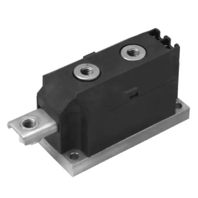
Part No.:
VSKC320-08
Manufacturer:
Vishay General Semiconductor - Diodes Division
Category:
Diode Arrays
Package:
3-MAGN-A-PAK™
Datasheet:
AetrixVSKC320-08.pdf
Description:
DIODE MOD GP 800V 320A MAGNAPAK
Quantity:
Payment:
Payment
Shipping:
Shipping

Inventory:6,860

Please send an inquiry. Send us your inquiry, and we will respond immediately.

Part Number
Quantity*
Price
Name*
Company
Email*
Comments

Product details

Overview

VSKC320-08 from Vishay Semiconductors is a single-phase, common-cathode dual-diode MAGN-A-PAK power module rated for 320 A average forward current (IF(AV)), 800 V maximum repetitive peak reverse voltage (VRRM), and 3000 VRMS isolation between terminals and base plate. It employs standard recovery silicon diodes in an electrically isolated metal-base package, designed for high-current industrial rectification in battery chargers, electroplating systems, and motor drive DC links.

For engineers reviewing the VSKC320-08 datasheet, VSKC320-08 pinout, VSKC320-08 application, or VSKC320-08 equivalent, this module delivers verified thermal performance (RthJC = 0.125 K/W), high surge capability (IFSM = 10,110 A at 50 Hz), and UL E78996 certification - critical for high-reliability, high-power AC/DC conversion designs requiring creepage, isolation, and mechanical robustness.

Technical Context

The VSKC320-08 integrates two standard recovery diodes in a common-cathode configuration within a single MAGN-A-PAK housing, enabling full-wave bridge construction with external anode connections. Its electrically isolated base plate allows direct mounting to shared heatsinks without insulating washers, reducing thermal resistance and simplifying mechanical assembly.

It operates across -40 °C to +150 °C junction temperature range, supports 180° sinusoidal conduction up to 320 A at 100 °C case temperature, and exhibits low forward voltage drop (VFM = 1.28 V at π × IF(AV)) with dual-slope conduction characteristics (VF(TO)1 = 0.69 V, rf1 = 0.59 mΩ).

Key Specifications

Parameter Value and Actual Design Meaning
IF(AV) 320 A - Maximum average forward current at 100 °C case temperature under 180° half-sine conduction; defines continuous DC output capability in rectifier applications.
VRRM 800 V - Maximum repetitive peak reverse voltage; determines maximum AC input voltage the module can block in line-frequency rectifiers.
IFSM (50 Hz) 10,110 A - Non-repetitive surge current rating; enables reliable operation during short-circuit events or inrush in welders and plating supplies.
RthJC 0.125 K/W - Junction-to-case thermal resistance per diode; directly impacts heatsink sizing and steady-state temperature rise under load.
VINS 3000 VRMS - RMS insulation voltage between all terminals and base plate; satisfies safety isolation requirements for industrial equipment per UL E78996.
VFM 1.28 V - Forward voltage drop at π × IF(AV) and TJ = 150 °C; sets conduction loss baseline for efficiency calculations in high-current DC bus designs.
I²t (t = 10 ms) 511 kA²s - Fusing I²t rating; used to coordinate upstream fuse selection for protection against sustained overcurrent faults.

Pinout & Package

MAGN-A-PAK package: metal base plate with three M8 mounting screws, insulated terminals, and standardized industrial footprint (115 mm × 80 mm × 32 mm). Electrically isolated base enables direct heatsink attachment without additional insulation.

Pin/Terminal Circuit Role Design Meaning
Anode 1 (A1) Input terminal for first diode Connects to AC phase 1 or transformer secondary leg; carries full forward current during positive half-cycle.
Anode 2 (A2) Input terminal for second diode Connects to AC phase 2 or transformer secondary leg; enables full-wave rectification when paired with A1.
Cathode (K) Common output node Shared cathode connection delivering rectified DC output; rated for full 320 A average current and must be sized accordingly in busbar layout.

Key Features

Feature Design Value
Electrically isolated base plate Enables direct mounting to grounded heatsinks without thermal interface insulation, reducing RthCS to 0.035 K/W and simplifying mechanical integration.
UL E78996 certification Validates compliance with industrial safety standards for creepage, clearance, and dielectric strength - required for CE-marked equipment in battery charging and plating systems.
High surge capability (IFSM = 10,110 A) Supports operation in high-inertia loads like motor drives and arc welders where transient overcurrents exceed nominal ratings without failure.
Large creepage distances Ensures reliable long-term insulation performance in humid, dusty, or conductive environments typical of industrial plating tanks and electrochemical processes.
RoHS-compliant construction Fulfills Directive 2011/65/EU requirements, enabling global deployment in environmentally regulated industrial electronics supply chains.

Applications

Battery Charging Systems Industrial Electroplating Equipment

Use Scenario: High-current DC power supply for nickel-chromium or zinc plating lines operating continuously at 200–300 A.

IC Role / Device Role / Timing Role: Dual-diode rectifier module converting three-phase AC to stable DC output; common-cathode topology simplifies busbar routing and reduces component count vs. discrete diode solutions.

Use Value: 320 A IF(AV) and 0.125 K/W RthJC enable compact heatsinking and >95 % efficiency at full load, minimizing energy waste and thermal management cost.

Use Scenario: Rectification stage in 500 V, 250 A DC power supply for copper electrowinning cells.

IC Role / Device Role / Timing Role: High-voltage, high-current diode module providing galvanically isolated DC output; electrically isolated base eliminates need for insulating hardware on shared busbar heatsinks.

Use Value: 3000 VRMS isolation and UL E78996 approval ensure personnel safety and regulatory compliance in wet, corrosive plating environments.

AC Motor Drive DC Link Resistance Welding Power Supply

Use Scenario: Input rectifier for 400 VAC, 30 kW variable frequency drive feeding induction motors in HVAC and pump systems.

IC Role / Device Role / Timing Role: Common-cathode dual-diode module forming half of a six-pulse bridge; handles bidirectional reactive current during regeneration and maintains DC bus stability.

Use Value: 10,110 A IFSM withstands regenerative surges and short-circuit transients without degradation, extending system uptime and reducing maintenance frequency.

Use Scenario: Primary rectifier in capacitor-discharge resistance welder delivering 10 kA pulses at 100 ms duration.

IC Role / Device Role / Timing Role: High-current, standard-recovery diode module conducting high-duty-cycle pulsed DC; optimized thermal mass and low RthJC prevent thermal runaway during repetitive welding cycles.

Use Value: 511 kA²s I²t rating ensures precise coordination with fast-acting DC fuses, protecting downstream thyristor stacks and transformer windings.

Equivalent & Alternatives

The following parts are listed as comparable options for similar high-current diode module applications.

Alternative Part Technical Difference Application Difference Selection Advice
VSKC320-12 Higher VRRM (1200 V) and VRSM (1300 V); identical IF(AV), IFSM, and thermal specs. Suitable for 690 VAC industrial mains or higher DC bus voltages; not interchangeable without circuit re-rating. Select VSKC320-12 only when system peak reverse voltage exceeds 800 V - no change to heatsink or mounting required.
VSKE320-08 Single-diode configuration (one anode, one cathode); same VRRM, IF(AV), and RthJC; lower I²t (361 kA²s). Used where unidirectional rectification suffices (e.g., freewheeling in thyristor-controlled drives); requires two units for full-wave bridge. Choose VSKE320-08 for modular flexibility or redundancy-critical designs; expect +100 % footprint and interconnect complexity vs. VSKC320-08.

Compared with VSKC320-12, the VSKC320-08 offers lower voltage derating margin but identical thermal and surge performance; versus VSKE320-08, it delivers full-wave rectification in one package, reducing part count and busbar losses by eliminating one series diode drop.

Availability

VSKC320-08 is available at Aetrix Electronics and suitable for battery charging systems, industrial electroplating equipment, and AC motor drive DC links requiring stable component supply, long-life reliability, and certified isolation performance.

Supply support for VSKC320-08 includes scheduled delivery planning, volume procurement assistance, BOM continuity management, traceable sourcing, and lifecycle availability coordination for OEM customers, industrial embedded developers, connected-device designers, and electronics production programs.

Manufacturer

Vishay Semiconductors is a global leader in discrete semiconductors and passive components, specializing in high-reliability power devices for industrial, automotive, and computing markets.

The VSK series was developed specifically for high-current, high-isolation industrial rectification - targeting applications where mechanical simplicity, thermal efficiency, and safety certification are non-negotiable design requirements.

FAQ

What is the maximum case temperature for continuous operation of the VSKC320-08?

The VSKC320-08 is rated for continuous operation at a maximum case temperature (TC) of 100 °C while delivering its full 320 A average forward current. Exceeding this temperature requires derating per the conduction-angle curves in Figure 12 of the datasheet. Thermal design must maintain TC ≤ 100 °C under worst-case ambient and airflow conditions to ensure reliability and meet lifetime specifications.

Does the VSKC320-08 require insulating hardware when mounted to a heatsink?

No - the VSKC320-08 features an electrically isolated base plate rated for 3000 VRMS, allowing direct mounting to grounded or common heatsinks without mica washers or silicone pads. Mounting torque must be maintained at 4–6 Nm with thermal compound applied, and torque should be rechecked after ~3 hours to accommodate compound spread and ensure consistent thermal contact.

What is the forward voltage drop of the VSKC320-08 at rated current?

The VSKC320-08 has a maximum forward voltage drop (VFM) of 1.28 V when conducting π × IF(AV) = ~1005 A at TJ = 150 °C and 180° conduction. This value reflects total conduction loss per diode and is used to calculate power dissipation: Pcond ≈ VF(TO) × IF(AV) + rf × IF(RMS)² = ~410 W per diode at full load.

Can the VSKC320-08 be used in a three-phase bridge configuration?

Yes - two VSKC320-08 modules (common-cathode) can be combined with one VSKE320-08 (single diode) or three VSKC320-08 units configured with external wiring to form a three-phase full-wave bridge. The common-cathode topology simplifies DC bus layout but requires careful gate/anode routing to avoid cross-conduction in controlled rectifier systems.

Is the VSKC320-08 RoHS compliant and UL certified?

Yes - the VSKC320-08 is compliant with RoHS Directive 2011/65/EU and carries UL certification under file E78996. It meets UL 94 V-0 flammability rating and has been qualified for industrial-level operation including extended temperature cycling, humidity exposure, and vibration testing per Vishay's internal qualification standards.

VSKC320-08 Specifications

Product attributes
Attribute value
Manufacturer:
Vishay General Semiconductor - Diodes Division
Series:
-
Package/Case:
3-MAGN-A-PAK™
Packaging:
Bulk
Product Status:
Obsolete
Diode Configuration:
1 Pair Common Cathode
Technology:
Standard
Voltage - DC Reverse (Vr) (Max):
800 V
Current - Average Rectified (Io) (per Diode):
320A
Voltage - Forward (Vf) (Max) @ If:
-
Speed:
Standard Recovery >500ns, > 200mA (Io)
Reverse Recovery Time (trr):
-
Current - Reverse Leakage @ Vr:
50 mA @ 800 V
Operating Temperature - Junction:
-
Grade:
-
Qualification:
-
Mounting Type:
Chassis Mount
Supplier Device Package:
MAGN-A-PAK®

VSKC320-08 FAQ

1.How can I place an order for VSKC320-08 through Aetrix?

Please submit a Request for Quotation (RFQ) for VSKC320-08 on Aetrix. Our sales agent will provide a competitive quotation and guide you through the order confirmation once you accept the terms.

2.Are the price and stock information for VSKC320-08 reliable?

The price and inventory of VSKC320-08 are updated periodically and may fluctuate due to market conditions. Stock and pricing data are typically refreshed every 24 hours. Quotation validity for VSKC320-08 is usually 5 days.

3.What payment methods are accepted for VSKC320-08?

We accept Wire Transfer, PayPal, Credit Card, Western Union, MoneyGram, and Escrow for VSKC320-08 transactions.

Note: Certain payment methods may incur a processing fee.

4.How is shipping managed for VSKC320-08?

VSKC320-08 orders can be shipped via leading logistics carriers, including DHL, UPS, FedEx, TNT, or Registered Mail.

Once your VSKC320-08 order is processed, you will receive an email with the shipment details and tracking number.

Note: Tracking information may take up to 24 hours to appear. Express delivery typically takes 3–5 business days.

5.How can I obtain technical support or documentation for VSKC320-08?

For technical support, including VSKC320-08 datasheets, pinout diagrams, or application guidance, please contact our engineering support team. They can provide detailed documentation and assistance for your VSKC320-08 requirements.

6.How does Aetrix verify that VSKC320-08 is sourced from the original manufacturer or authorized distributors?

All VSKC320-08 products on Aetrix are procured from qualified distributors and authorized channels. Our dedicated quality assurance team conducts strict verification, including traceability checks and, if necessary, third-party testing. This ensures that VSKC320-08 meets industry standards.

7.What is the process for return or replacement of VSKC320-08?

All VSKC320-08 units undergo pre-shipment inspection (PSI). If there is an issue with VSKC320-08, returns or replacements are accepted under the following conditions:

1.Quantity discrepancies, incorrect items, or visible external defects (such as breakage or corrosion), acknowledged by Aetrix.

2.The issue is reported within 90 days of delivery.

3.The VSKC320-08 part is unused and in its original packaging.

Return procedure for VSKC320-08:

1.Submit a request within 90 days.

2.Obtain a Return Material Authorization (RMA) from Aetrix.

VSKC320-08 Tags
  • VSKC320-08
  • VSKC320-08 PDF
  • VSKC320-08 Datasheet
  • VSKC320-08 Specifications
  • VSKC320-08 Images
  • Vishay General Semiconductor - Diodes Division
  • Vishay General Semiconductor - Diodes Division VSKC320-08
  • Buy VSKC320-08
  • VSKC320-08 Price
  • VSKC320-08 Distributor
  • VSKC320-08 Supplier
  • VSKC320-08 Wholesale
Related Products
BAV99-7-F
BAV99-7-F

Diodes Incorporated

BAT54C-7-F
BAT54C-7-F

Diodes Incorporated

BAV99,215
BAV99,215

Nexperia USA Inc.

BAT54SLT1G
BAT54SLT1G

onsemi

BAV70LT1G
BAV70LT1G

onsemi

BAT54CLT1G
BAT54CLT1G

onsemi

BAT54S-7-F
BAT54S-7-F

Diodes Incorporated

BAV99LT1G
BAV99LT1G

onsemi

BAT54S,215
BAT54S,215

Nexperia USA Inc.

BAS40-04LT1G
BAS40-04LT1G

onsemi

MMBD1503-TP
MMBD1503-TP

Micro Commercial Co

BAV99WT1G
BAV99WT1G

onsemi

Tech Hub

Search

Search

PRODUCT

PRODUCT

PHONE

PHONE

USER

USER