Send an Inquiry

To receive a quote for your project, please fill in the following information, and we’ll get back to you promptly.

Name*
Company*
Email Address*
Phone/WhatsApp
Part Number*
Quantity*
Message
Submit Inventory List

Please fill in the following information, and we’ll get back to you promptly.

Name*
Company*
Email Address*
Phone/WhatsApp
Upload My List
Message

Vishay General Semiconductor - Diodes Division VS-VSKD166/14PBF
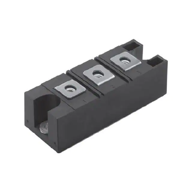
Part No.:
VS-VSKD166/14PBF
Manufacturer:
Vishay General Semiconductor - Diodes Division
Category:
Diode Arrays
Package:
INT-A-Pak
Datasheet:
AetrixVS-VSKD166/14PBF.pdf
Description:
DIODE MOD GP 1400V 82.5A INTAPAK
Quantity:
Payment:
Payment
Shipping:
Shipping

Inventory:3,804

Please send an inquiry. Send us your inquiry, and we will respond immediately.

Part Number
Quantity*
Price
Name*
Company
Email*
Comments

Product details

Overview

VS-VSKD166/14PBF from Vishay Semiconductors is a high-voltage, standard-recovery power diode module in INT-A-PAK package, configured as a two-diode doubler circuit, rated for 165 A average forward current (IF(AV)), 400 V maximum repetitive peak reverse voltage (VRRM), and 3500 VRMS isolation. It uses glass-passivated chips mounted on DBC ceramic (Al₂O₃) for electrical isolation and thermal performance, and is UL approved (E78996) for industrial power conversion systems.

For engineers reviewing the VS-VSKD166/14PBF datasheet, VS-VSKD166/14PBF pinout, VS-VSKD166/14PBF application, or VS-VSKD166/14PBF equivalent, this module supports high-surge, high-current DC motor drives, battery chargers, welders, and single-phase bridge converters requiring robust thermal management, galvanic isolation, and stable conduction at 100 °C case temperature.

Technical Context

The VS-VSKD166/14PBF implements a two-diode doubler configuration - two series-connected diodes sharing a common terminal - enabling voltage-doubling rectification in high-power AC-to-DC conversion. Its DBC Al₂O₃ substrate provides 3500 VRMS insulation between circuit and baseplate, supporting safe operation in grounded-heatsink topologies.

Thermally, it delivers 0.20 K/W junction-to-case resistance per diode under DC operation, with low on-state slope resistances (rt1 = 1.5 mΩ, rt2 = 1.26 mΩ) and threshold voltages (VF(TO)1 = 0.73 V, VF(TO)2 = 0.88 V) optimized for high-efficiency conduction at IF(AV) = 165 A and TJ = 150 °C.

Key Specifications

Parameter Value and Actual Design Meaning
IF(AV) 165 A - maximum average forward current at 100 °C case temperature, defining continuous DC output capability in rectifier bridges
VRRM 400 V - maximum repetitive peak reverse voltage, sets safe blocking margin for 280 V RMS AC input applications
IFSM (t = 10 ms) 4000 A - non-repetitive surge current rating, supports short-circuit withstand in welder and motor drive fault conditions
RthJC 0.20 K/W per junction - thermal resistance from junction to case, enables 33 W max power dissipation per diode at ΔT = 6.6 K
VFM 1.43 V - forward voltage drop at π × IF(AV) ≈ 518 A and 25 °C, directly determining conduction loss in high-current switching cycles
IRRM 20 mA at 150 °C - peak reverse leakage current, critical for thermal stability in high-temperature battery charger hold-off stages
VINS 3500 VRMS - RMS insulation voltage between terminals and baseplate, satisfies safety isolation requirements for Class I industrial equipment

Pinout & Package

VS-VSKD166/14PBF uses the INT-A-PAK industrial power module package: 94.4 mm × 36.6 mm × 23 mm metal baseplate with three M6 mounting screws, DBC Al₂O₃ ceramic isolation, and four external terminals (A1, K1, A2, K2) arranged in a doubler configuration.

Pin/Terminal Circuit Role Design Meaning
A1 Anode of Diode 1 Input terminal for first diode in doubler chain; connects to AC line or transformer secondary
K1 / A2 Cathode of Diode 1 / Anode of Diode 2 Interconnection node - carries full output current and defines mid-point voltage in doubler topology
K2 Cathode of Diode 2 Output terminal - delivers doubled DC voltage referenced to system ground or heatsink
Baseplate Isolated thermal path & safety ground reference Electrically isolated via 3500 VRMS DBC ceramic; mounts directly to heatsink without insulating washer

Key Features

Feature Design Value
DBC Al₂O₃ isolation Enables direct-mount heatsinking while maintaining 3500 VRMS safety barrier - eliminates need for isolating pads or bushings
Two-diode doubler configuration Provides 2× input AC peak voltage at output without center-tapped transformer - reduces transformer size/cost in high-voltage battery chargers
High surge capability (4000 A IFSM) Withstands 10 ms half-sine surges during welder arc ignition or motor startup, reducing need for external crowbar protection
Glass-passivated chips Ensures long-term reliability under humidity, thermal cycling, and high dv/dt stress in industrial converter environments
UL approval (E78996) Validates compliance with UL 60950-1/IEC 62368-1 for end-equipment safety certification - accelerates regulatory approval timelines

Applications

DC Motor Drives Battery Chargers

Use Scenario: High-power 3-phase rectification feeding SCR or IGBT inverter stages for industrial servo motors.

IC Role / Device Role / Timing Role: Doubler-configured diode module serves as front-end voltage-boosting rectifier, doubling AC line voltage before DC link filtering.

Use Value: Enables higher DC bus voltage from same transformer, improving inverter efficiency and torque density without increasing transformer VA rating.

Use Scenario: Off-board EV charger or telecom backup system converting 230 VAC to 800 VDC for Li-ion stack charging.

IC Role / Device Role / Timing Role: VS-VSKD166/14PBF operates as doubler rectifier in active front-end stage, delivering regulated high-voltage DC output.

Use Value: Achieves 800 V output from 230 VAC input using single-stage doubler - avoids complexity and losses of dual-stage PFC + boost architectures.

Welding Power Supplies Industrial Power Converters

Use Scenario: Inverter-based arc welder with dynamic current control requiring fast recovery and high surge tolerance.

IC Role / Device Role / Timing Role: VS-VSKD166/14PBF functions as main rectifier in primary-side AC-DC conversion, handling intermittent 4000 A surges during arc strike.

Use Value: Sustains repeated 10 ms surges without thermal runaway or parameter drift, extending service life in high-duty-cycle welding cycles.

Use Scenario: Medium-voltage UPS or renewable energy interface converting generator/microgrid AC to stabilized DC for battery storage.

IC Role / Device Role / Timing Role: Doubler module provides isolated, high-current DC output with minimal conduction loss (1.43 V @ 518 A) at ambient up to 70 °C.

Use Value: Low RthJC (0.20 K/W) and high IF(RMS) (260 A) allow compact heatsink design while maintaining <150 °C junction temperature under full load.

Equivalent & Alternatives

The following parts are listed as comparable options for similar high-current, high-voltage doubler diode module applications.

Alternative Part Technical Difference Application Difference Selection Advice
IXYS MDD165-16N1 165 A / 1600 V, TO-247-3L single-diode; requires external doubler wiring and separate isolation Lacks integrated doubler topology and DBC isolation - needs additional PCB layout, insulators, and thermal interface layers Select when higher VRRM (>1000 V) is required and board space allows discrete implementation with custom isolation
Vishay VS-VSKJ166/14PBF Same IF(AV)/VRRM ratings but common-anode dual-diode configuration (not doubler); identical INT-A-PAK footprint and thermal specs Suitable for full-wave bridge legs or parallel diode arrays - not usable in voltage-doubling topologies without circuit redesign Choose for bridge rectifier designs where anode-common pairing simplifies gate drive or snubber layout, not for doubler circuits

Compared with IXYS MDD165-16N1, VS-VSKD166/14PBF integrates the doubler function and DBC isolation in one package, reducing BOM count and assembly risk; versus VS-VSKJ166/14PBF, it delivers unique voltage multiplication capability but cannot substitute in common-anode bridge configurations.

Availability

VS-VSKD166/14PBF is available at Aetrix Electronics and suitable for DC motor drives, battery chargers, and welding power supplies requiring stable component supply, long-lifecycle support, and certified industrial-grade isolation.

Supply support for VS-VSKD166/14PBF includes scheduled delivery planning, volume procurement assistance, BOM continuity management, traceable sourcing, and lifecycle availability coordination for OEM customers, industrial embedded developers, connected-device designers, and electronics production programs.

Manufacturer

Vishay Semiconductors is a global leader in discrete semiconductors and passive components, specializing in high-reliability power devices for industrial, automotive, and computing markets.

The VS-VSK series targets high-power industrial rectification, designed specifically for voltage-doubling, welder, and motor drive applications where galvanic isolation, surge resilience, and thermal robustness are mandatory.

FAQ

What is the circuit configuration of VS-VSKD166/14PBF?

VS-VSKD166/14PBF is configured as a two-diode doubler circuit: Diode 1 anode (A1) and Diode 2 cathode (K2) are external terminals, while Diode 1 cathode and Diode 2 anode share the internal node (K1/A2). This topology enables AC voltage doubling without a center-tapped transformer, and is confirmed in Vishay document 94357, Figure "CIRCUIT CONFIGURATION" and ordering code 'D'.

Does VS-VSKD166/14PBF require an insulating pad when mounted to a heatsink?

No, VS-VSKD166/14PBF does not require an insulating pad. Its DBC Al₂O₃ ceramic substrate provides 3500 VRMS isolation between all terminals and the metal baseplate, allowing direct mounting to an electrically grounded heatsink - a key feature verified in the "FEATURES" section and thermal specifications of Vishay document 94357.

What is the maximum allowable case temperature for VS-VSKD166/14PBF?

The maximum allowable case temperature for VS-VSKD166/14PBF is 100 °C, as specified in the "MAJOR RATINGS AND CHARACTERISTICS" table of Vishay document 94357. This limit applies under 180° conduction, half-sine wave conditions and ensures reliable operation within the -40 °C to +150 °C junction temperature range.

How does the forward voltage of VS-VSKD166/14PBF vary with current and temperature?

VS-VSKD166/14PBF exhibits two-region forward conduction: VF(TO)1 = 0.73 V (low-level threshold) and VF(TO)2 = 0.88 V (high-level threshold) at TJ = 150 °C, with slope resistances rt1 = 1.5 mΩ and rt2 = 1.26 mΩ. These values define the linearized V–I curve used to calculate real-world conduction loss across its 165 A operating range.

Is VS-VSKD166/14PBF RoHS-compliant and lead-free?

Yes, VS-VSKD166/14PBF is RoHS-compliant and lead-free, as indicated by the "PbF" suffix in its full part number and explicitly stated in the series title "VS-VSK.166..PbF, VS-VSK.196..PbF, VS-VSK.236..PbF Series" in Vishay document 94357, Revision 04-May-17.

VS-VSKD166/14PBF Specifications

Product attributes
Attribute value
Manufacturer:
Vishay General Semiconductor - Diodes Division
Series:
-
Package/Case:
INT-A-Pak
Packaging:
Bulk
Product Status:
Active
Diode Configuration:
1 Pair Common Cathode
Technology:
Standard
Voltage - DC Reverse (Vr) (Max):
1400 V
Current - Average Rectified (Io) (per Diode):
82.5A
Voltage - Forward (Vf) (Max) @ If:
-
Speed:
Standard Recovery >500ns, > 200mA (Io)
Reverse Recovery Time (trr):
-
Current - Reverse Leakage @ Vr:
20 mA @ 1400 V
Operating Temperature - Junction:
-40°C ~ 150°C
Grade:
-
Qualification:
-
Mounting Type:
Chassis Mount
Supplier Device Package:
INT-A-PAK

VS-VSKD166/14PBF FAQ

1.How can I place an order for VS-VSKD166/14PBF through Aetrix?

Please submit a Request for Quotation (RFQ) for VS-VSKD166/14PBF on Aetrix. Our sales agent will provide a competitive quotation and guide you through the order confirmation once you accept the terms.

2.Are the price and stock information for VS-VSKD166/14PBF reliable?

The price and inventory of VS-VSKD166/14PBF are updated periodically and may fluctuate due to market conditions. Stock and pricing data are typically refreshed every 24 hours. Quotation validity for VS-VSKD166/14PBF is usually 5 days.

3.What payment methods are accepted for VS-VSKD166/14PBF?

We accept Wire Transfer, PayPal, Credit Card, Western Union, MoneyGram, and Escrow for VS-VSKD166/14PBF transactions.

Note: Certain payment methods may incur a processing fee.

4.How is shipping managed for VS-VSKD166/14PBF?

VS-VSKD166/14PBF orders can be shipped via leading logistics carriers, including DHL, UPS, FedEx, TNT, or Registered Mail.

Once your VS-VSKD166/14PBF order is processed, you will receive an email with the shipment details and tracking number.

Note: Tracking information may take up to 24 hours to appear. Express delivery typically takes 3–5 business days.

5.How can I obtain technical support or documentation for VS-VSKD166/14PBF?

For technical support, including VS-VSKD166/14PBF datasheets, pinout diagrams, or application guidance, please contact our engineering support team. They can provide detailed documentation and assistance for your VS-VSKD166/14PBF requirements.

6.How does Aetrix verify that VS-VSKD166/14PBF is sourced from the original manufacturer or authorized distributors?

All VS-VSKD166/14PBF products on Aetrix are procured from qualified distributors and authorized channels. Our dedicated quality assurance team conducts strict verification, including traceability checks and, if necessary, third-party testing. This ensures that VS-VSKD166/14PBF meets industry standards.

7.What is the process for return or replacement of VS-VSKD166/14PBF?

All VS-VSKD166/14PBF units undergo pre-shipment inspection (PSI). If there is an issue with VS-VSKD166/14PBF, returns or replacements are accepted under the following conditions:

1.Quantity discrepancies, incorrect items, or visible external defects (such as breakage or corrosion), acknowledged by Aetrix.

2.The issue is reported within 90 days of delivery.

3.The VS-VSKD166/14PBF part is unused and in its original packaging.

Return procedure for VS-VSKD166/14PBF:

1.Submit a request within 90 days.

2.Obtain a Return Material Authorization (RMA) from Aetrix.

VS-VSKD166/14PBF Tags
  • VS-VSKD166/14PBF
  • VS-VSKD166/14PBF PDF
  • VS-VSKD166/14PBF Datasheet
  • VS-VSKD166/14PBF Specifications
  • VS-VSKD166/14PBF Images
  • Vishay General Semiconductor - Diodes Division
  • Vishay General Semiconductor - Diodes Division VS-VSKD166/14PBF
  • Buy VS-VSKD166/14PBF
  • VS-VSKD166/14PBF Price
  • VS-VSKD166/14PBF Distributor
  • VS-VSKD166/14PBF Supplier
  • VS-VSKD166/14PBF Wholesale
Related Products
BAV99-7-F
BAV99-7-F

Diodes Incorporated

BAT54C-7-F
BAT54C-7-F

Diodes Incorporated

BAV99,215
BAV99,215

Nexperia USA Inc.

BAT54SLT1G
BAT54SLT1G

onsemi

BAV70LT1G
BAV70LT1G

onsemi

BAT54CLT1G
BAT54CLT1G

onsemi

BAT54S-7-F
BAT54S-7-F

Diodes Incorporated

BAV99LT1G
BAV99LT1G

onsemi

BAT54S,215
BAT54S,215

Nexperia USA Inc.

BAS40-04LT1G
BAS40-04LT1G

onsemi

MMBD1503-TP
MMBD1503-TP

Micro Commercial Co

BAV99WT1G
BAV99WT1G

onsemi

Tech Hub

Search

Search

PRODUCT

PRODUCT

PHONE

PHONE

USER

USER